peter.king@LIGO.ORG - posted 16:54, Tuesday 26 February 2019 - last comment - 15:27, Wednesday 06 March 2019(47140)
FSS work
A quick entry whilst things are still fresh in my memory, more details to follow.

    Adjusted the double pass alignment through the AOM.  Re-centered L12 and the 21.5 MHz EOM to match (component
names match those on the PSL table layout).  Without the 21.5 MHz connected, measured 43.8 mW at the base of the
periscope, and 40 mW after the polarising beamsplitter cube before the RF photodiode.  Measured 4.38 mW in front
of the RF photodiode.

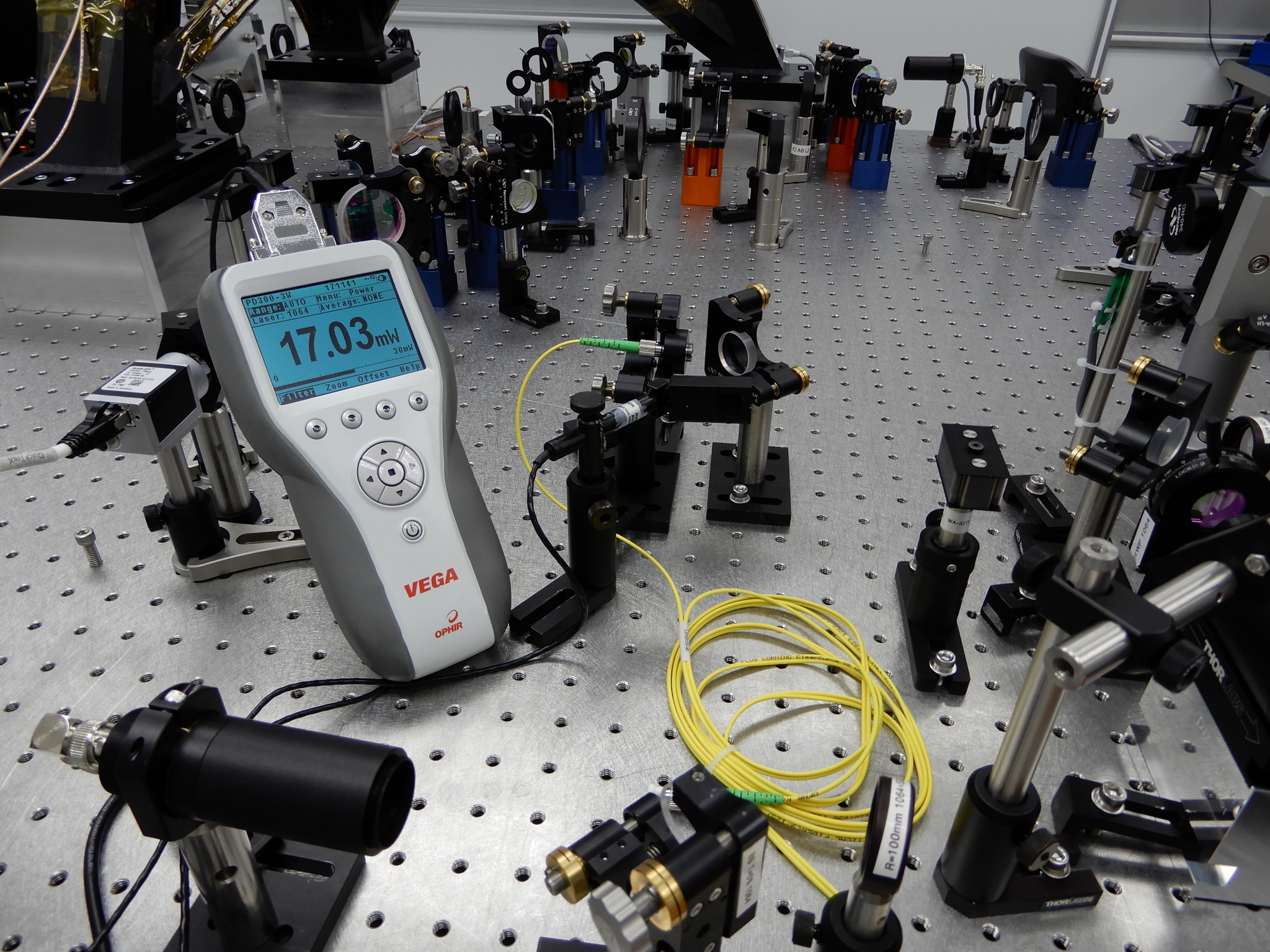
    Locked the FSS.  With a reference cavity transmission signal of 3 V, measured 17 mW in front of the ALS fibre
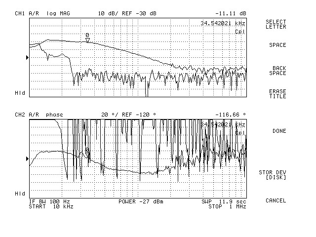
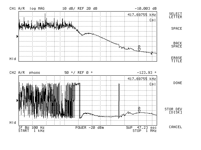
(see ALS_Fibre.JPG).  After the alignment tune up, measured the transfer function (see PC.jpg).  It was here where
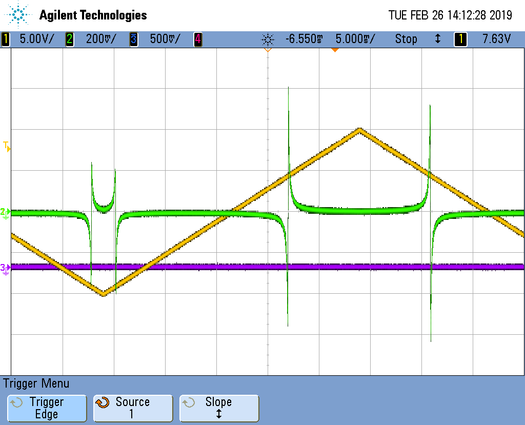
things went AWOL.  Swept the reference cavity by applying a ramp to the PZT and displayed the mixer monitor signal
on an oscilloscope (see scope_0.png).  This was noticeably different from the same measurement taken before lunch,
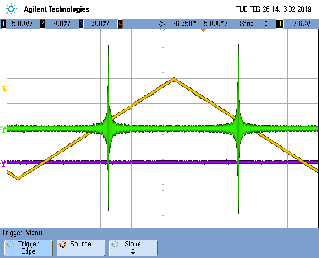
where the discriminator signal was less than ~10 mVpp.  The RF output of the RF photodiode is shown in scope_1.png.

    Left the FSS with a common gain of 25 and a fast gain of 16 (see CG25FG16.jpg) where the UGF is ~417 kHz.
Increasing the common gain slider by an extra dB or two to sit on the peak of the phase bubble makes the PZT
prone to oscillating.


  Jason / Peter
Images attached to this report
Comments related to this report
Also investigated the readback of the RF photodiode output.  Injecting a known voltage into the
breakout box (DB9 side) produced the correct number of counts displayed on the MEDM filter module
display associated with the RF photodiode DC readout (~150 counts for 10 V input).


  Richard / Fil / Peter
Images attached to this comment

Tried the slightly newer version of the TTFSS (2G).  Had to flip the RF phase by 180 to get the
servo to lock.  However with both the common and fast gain sliders at minimum the PZT was
oscillating.  The discriminator signal was a lot larger with the 2G TTFSS than with the TTFSS
currently installed.

    A 10 dB attenuator was inserted in the LO path to bring the LO monitor to be about the
same.  This because the 2G TTFSS has an RF amplifier inside.

    I will have to compare the electronic transfer function of the EOM path with the original
TTFSS.  I already know the PZT path is the same except for a notch filter.
Seems that, if 10V only gets you 150 cts on the ADC, it is broken.
Associated with FRS Ticket 12386.