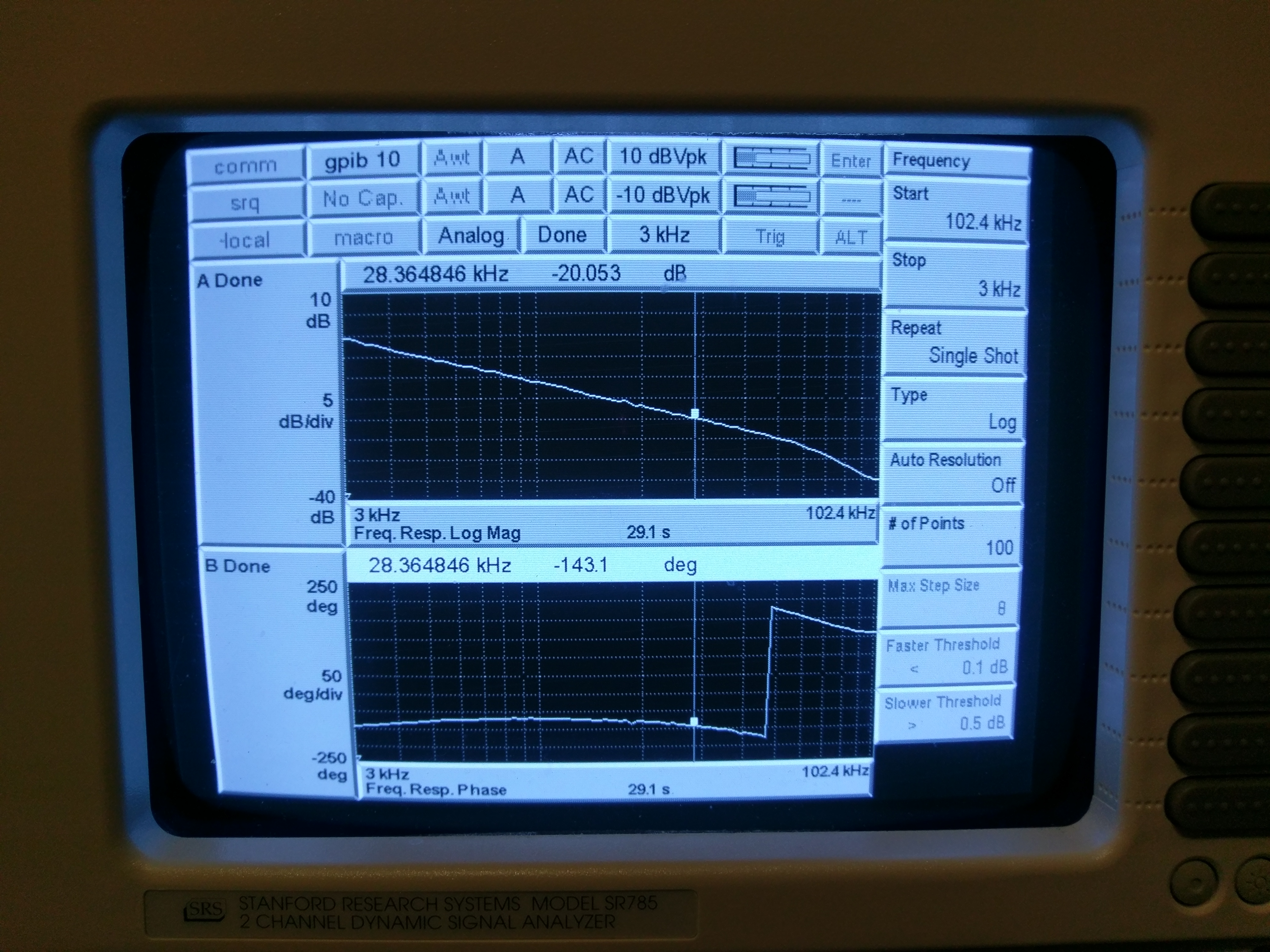
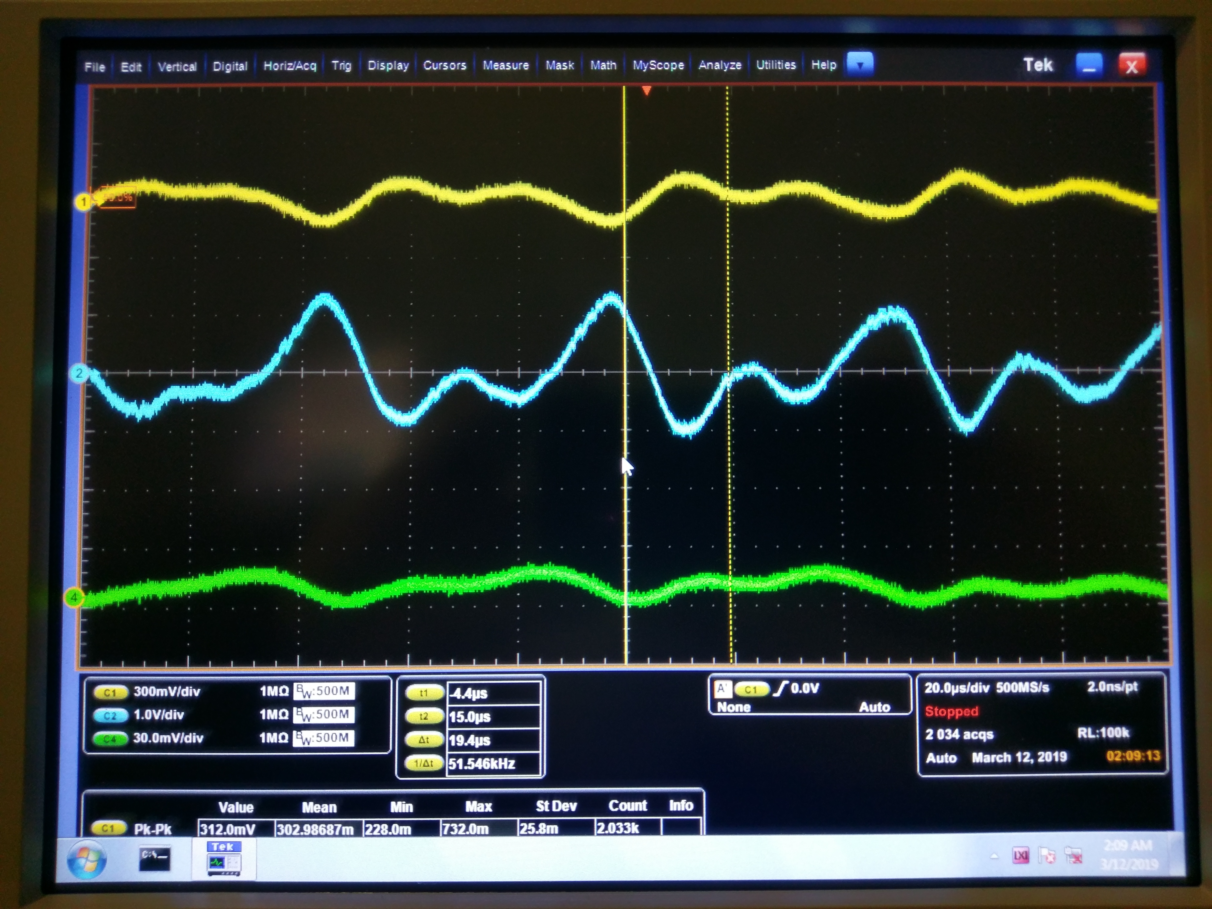
While IFO was down due to HEPI failure in the morning, I went to the floor to measure the ISS 2nd loop OLTF at 30W.
UGF was somewhat higher than 40kHz, phase margin less than 20 degrees. (First attachment, note that the measured TF is OLTF/10 due to the modification we made in January (alog 46317) where the summation opamp gain is -10 instead of -1. Sorry about confusing cursor position, I was confused when I took this picture.)
As the result there is a huge gain peaking at about 50kHz, producing about 5 to 6 Vpp at the output of the summation opamp, which is too large. (Second attachment, yellow is before the summation amp, blue is after. Didn't measure the output of the board.)
Later Georgia set the VGA gain 5 dB lower (H1:PSL-ISS_SECONDLOOP_GAIN will be 7dB instead of 12dB) in the guardian so that the UGF comes down to about 20kHz, with ~50deg phase margin.
Since we're trying to lock I won't repeat my measurements on the floor at the moment but we need to do it during EQ time or on Tuesday.
If you have an opportunity over the weekend, what you need to do is:
Set the laser power to 30W. Go to ISS_DC_COUPLED (IMC_LOCK guardian). Confirm that the VGA gain slider is at 7dB.
Go to the floor. At the back of the ISS 2nd loop chassis on the rightmost PSL rack, there are four BNC connectors labeled as ERR1, ERR2, EXC and board OUT.
Connect the excitation of SR785 to EXC, CHA to ERR2, CHB to ERR1.
In the MEDM screen, enable excitation input.
EXC voltage of 1000mV is OK. There's a 1/10 attenuation in the EXC path so this is not excessive. You'll have to integrate long (e.g. 0.1 sec or some such) to get a decent measurement.
Measure the OLTF. Note that the measured quantity is OLTF/10.
Disable EXC, disconnect EXC, connect ERR2 and ERR1 and OUT to a scope and measure the voltages. If you still see a huge gain peaking you want to lower the gain further.
This morning when H1 lost lock, I quickly went to the floor and made the same measurements, and things look OK.
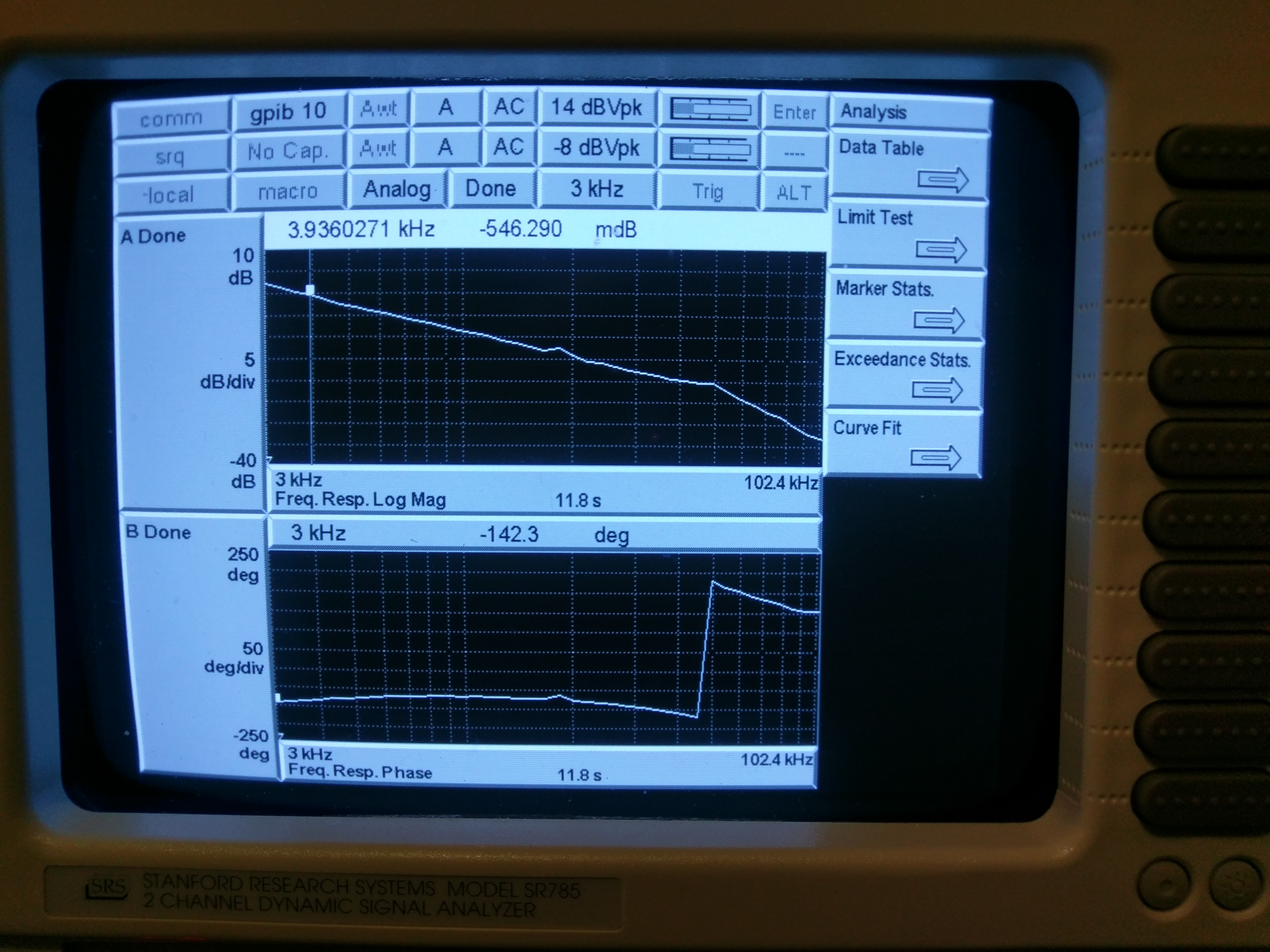
At 30W with 7dB VGA slider, UGF~28kHz, phase margin~37deg, which look good to me (first attachment).
Moving the slider back up to 12dB, the servo immediately started the oscillation at about 50kHz. Bringing it down to 11dB already quenched the oscillation.
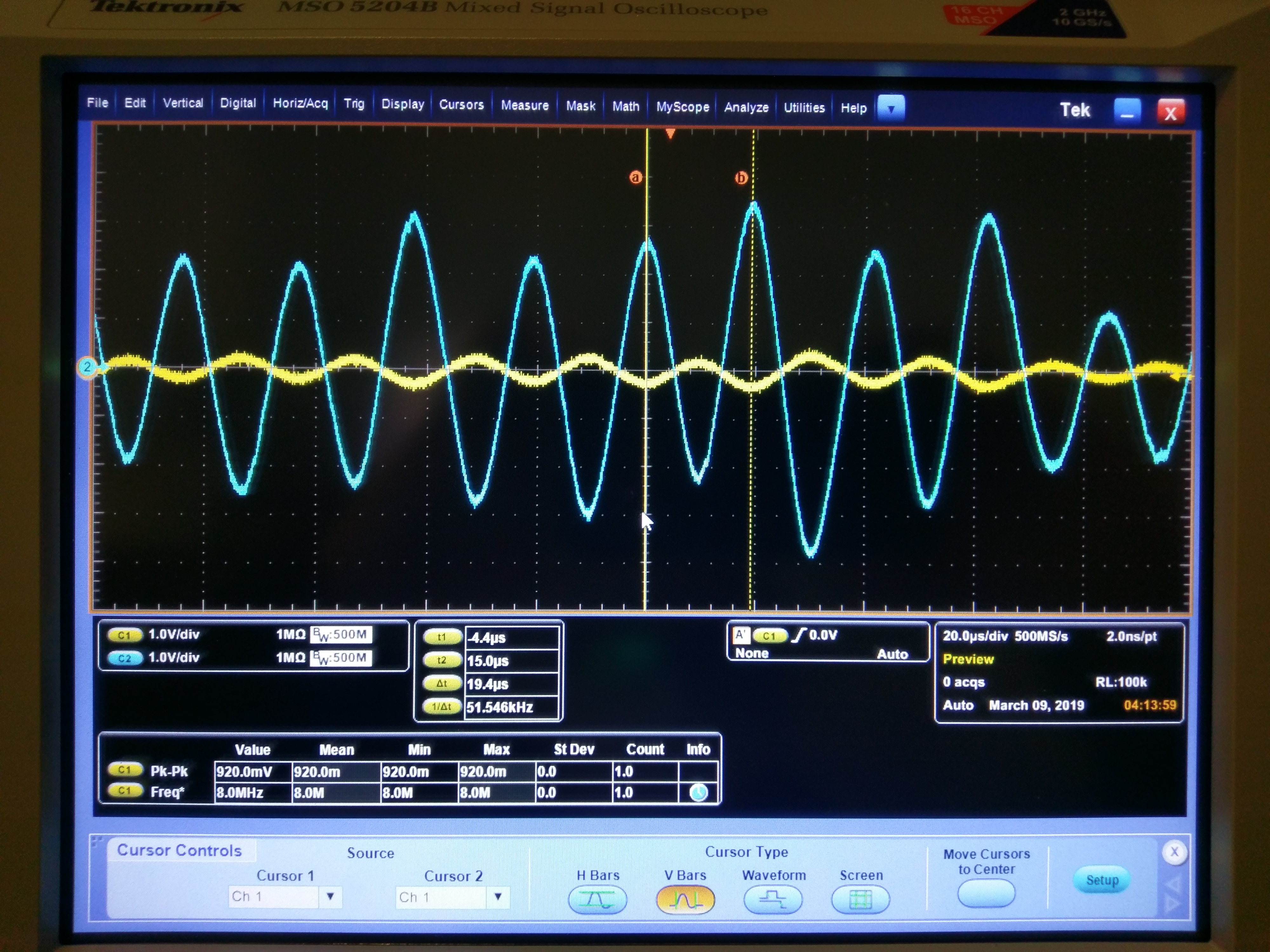
With the nominal gain of 7dB, the residual noise at around 50kHz was ~1Vpp after the x10 summation stage with maybe another 1+Vpp or so at around UGF (second attachment blue) which is larger than I'd like. However, the output of VGA with 7dB gain will be ~4.5+Vpp which would be large but OK. The output of the board was measured to be about 15~20mVpp or so (2nd attachment green), this is no problem for the 1st loop.
(The reason why the board output is small is because two fixed boost type filters downstream has about 2E-3 attenuation combined for f>20kHz.)