Keita, Sheila, Craig
We were confused about why my sign flip on the front end UIM stage helped flatten out the PCAL to DARM TF from last night. Keita and I checked all the front end calibration filters, and things seemed to make sense without a sign flip. We also injected some white noise during a lockloss and took a TF from CAL CS LOCK L3 IN1 to the calibrated outputs for each stage: H1:CAL-CS_DARM_ANALOG_ETMX_L{1,2,3}_OUT, as well as the summed total H1:CAL-CS_DARM_CTRL_DELAY_IN1, and compared this to Sheila's DARM model: the models matched well, and no sign flip seemed necessary.
This seems like a good method of verifying the front end calibration, the template is too big to attach but is exists at /ligo/home/controls/craig.cahillane/Calibration/FrontEndDARMCalibrationCheck.xml
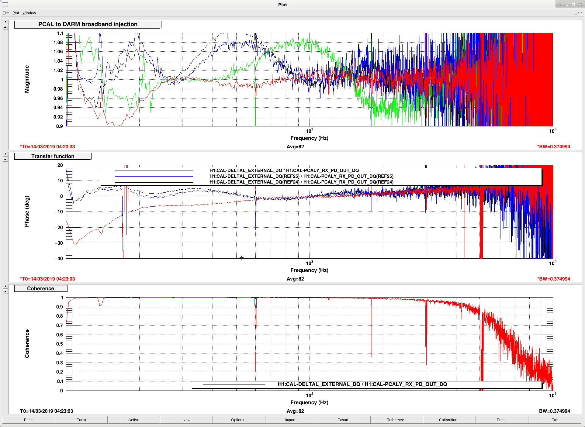
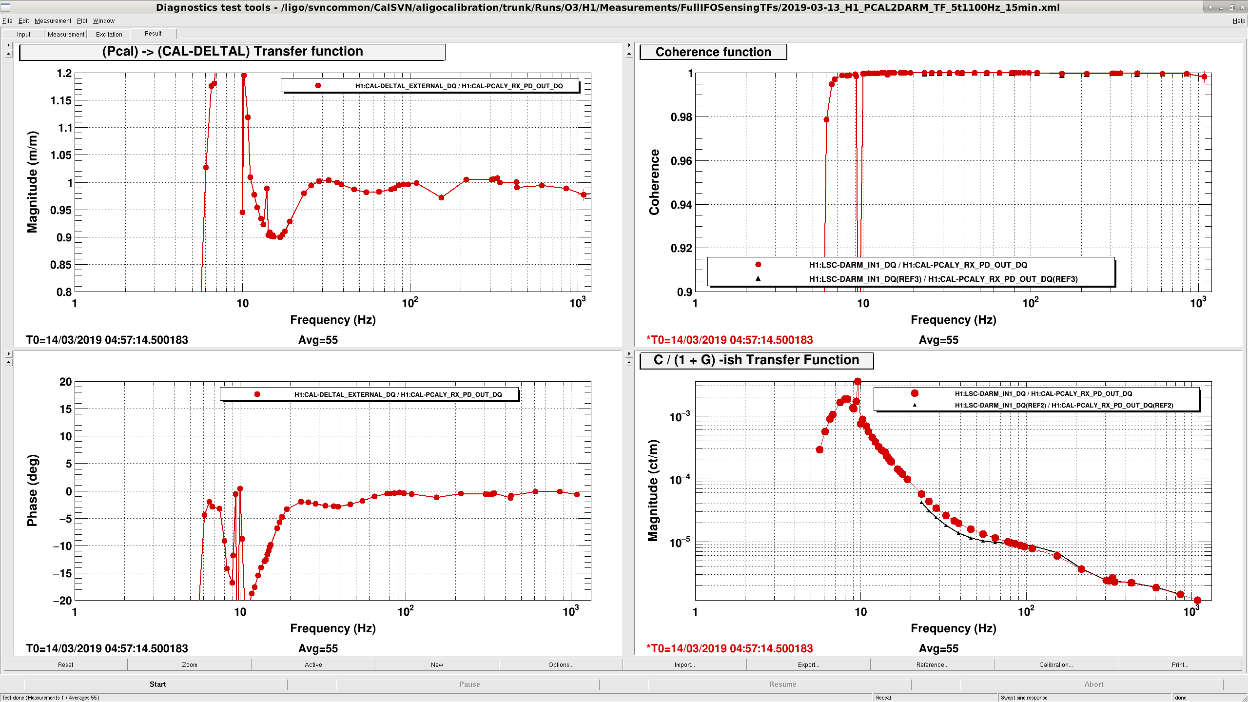
We reset all front end gains to 1.0 and remeasured PCAL to DARM. Things were good to 2% from 25 Hz to 1000 Hz using the sensing function fit from yesterday and Jeff's actuator gains from here. We decided to leave the front end calibration here, even though it underestimates DARM meters at 20 Hz by 10%, because the 20 Hz region doesn't have a huge effect on our reported BNS range. We recognize that this will be a problem for overestimating BBH range, but given the good match at higher frequencies this is the best calibration we have.
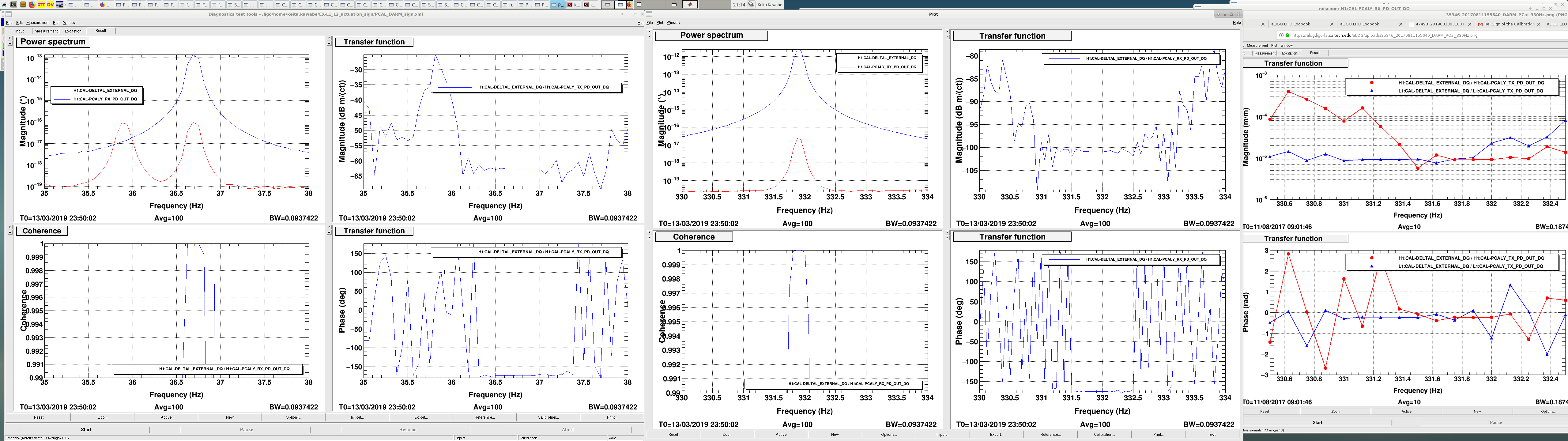
Overall calibration sign is incorrect for H1:CAL-DELTAL_EXTERNAL_DQ.
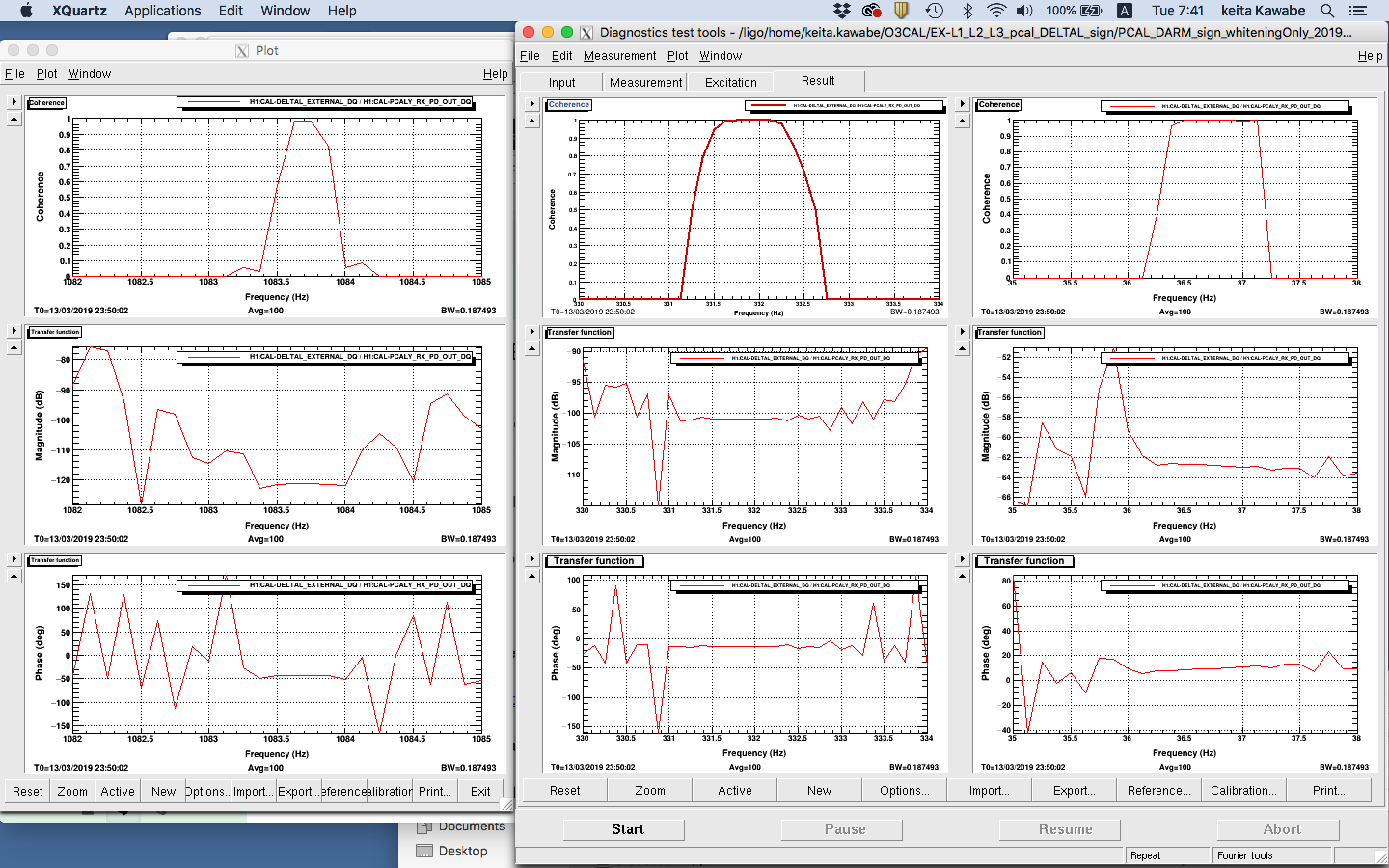
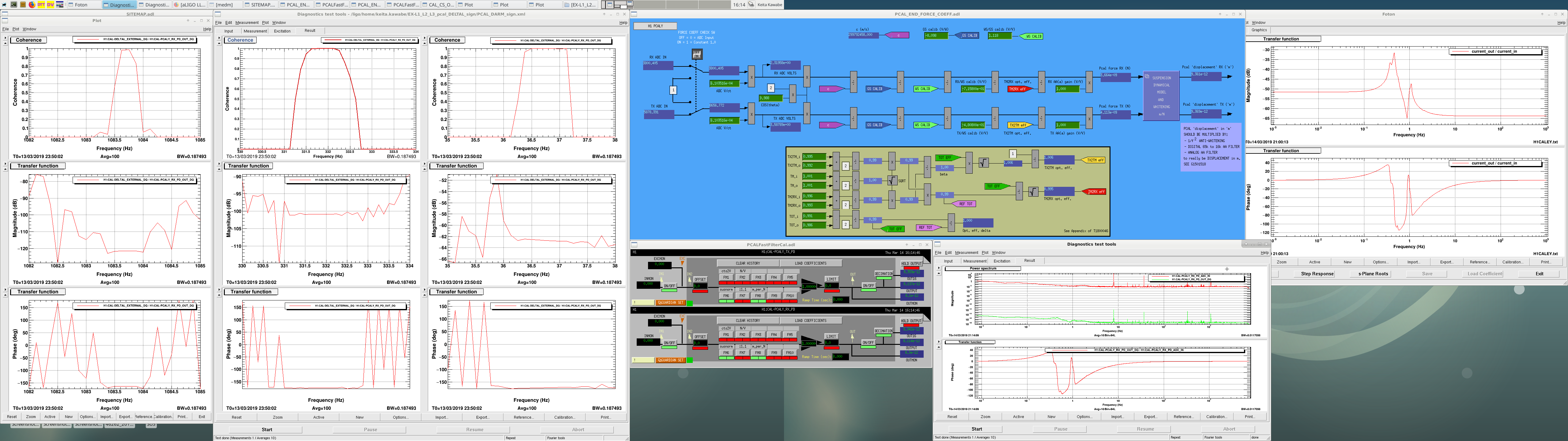
In the attached, left half shows the Pcal_X_RX_PD_OUT_DQ to DELTAL_EXTERNAL_DQ transfer function at three PCALY calline frequencies. DELTAL_EXTERNAL_DQ is calibrated in meters using H1DARMFOM dtt template, but I removed two 1Hz poles from PCAL_X_RX_PD so that basically it becomes the scaled power (positive means more power).
See how the phase of the TF is close to -180 deg at all three callines. This means that the overall sign of DELTAL channel is wrong. During O2, the same measurement showed tha both L1 and H1 were at ~0deg, which is the indication of correct sign (LLO alog 35346). This measurement is quite conclusive and that's the reason why we used this for LIGO and VIRGO calibration sign review in O2.
Incorrect sign is not because Craig did something, it has been like that for quite some time.
Let me explain the idea behind the measurement.
Let the Pcal power be P and the actuation function of Pcal be A such that the change in the Y arm length is
dY=AP.
LIGO-VIRGO sign convention is
dL=dX-dY
where positive dX or dY means longer X or Y arm.
The measured transfer function is
dL/P = (-dY)/P = -AP/P = -A.
Since Pcal pushes EY toward ERMY, A is positive at DC (i.e more power makes Y arm longer), but at frequencies much larger than the highest pendular resonance the test mass response is that of a free mass, so A is negative at e.g. ~36Hz and ~312Hz.
Therefore, if the sign of calibration is correct, power to DELTAL transfer function -A is positive, i.e. the phase is zero, not -180 deg.
Now, PCAL TX (transmitter) and RX (receiver) power channels are calibrated in a funny unit where the complex suspension response is embedded in the RX channel calibration itself (but only in part) as a calibration filter. That filter is shown in the foton (attached rightmost). Important thing is that DC phase as well as the phase for f>30Hz or so are both basically zero degree (phase=-3.2deg at 36Hz). In this sense, for f>30Hz, RX_PD_OUT is just a scaled version of the power. We know that the channel goes positive when there is light on the PD, goes zero when no light, so positive signal means more power.
RX_PD_OUT(f<0.01Hz or f>15Hz) = C*P
dL/RX_PD_OUT = dL/P/C where C is a positive number.
The measured quantity is just dL/P divided by a positive number.
Therefore, if the sign of calibration is correct, phase of RX_PD_OUT to DELTAL transfer function is zero, not -180 deg.
I could in principle do the same analysis using the channel without any calibration, e.g. CAL-PCALY_RX_PD_ADC_IN but this is not DQ channel so I cannot look back, which is inconvenient.
We're trying to get help from JeffK (who is not at the site) and JoeB to learn how to correct the sign in a calibration-mode-friendly way.
Great work, team!
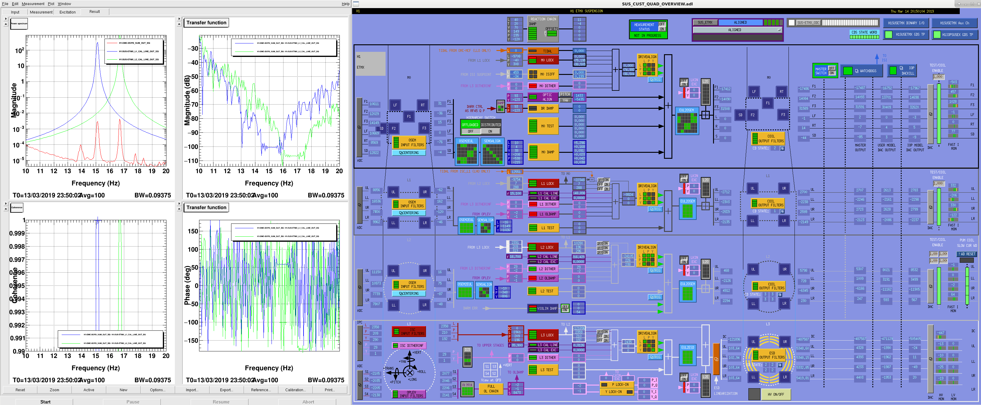
We also measured the relative sign of EX L1 and L2 using ~16Hz callines on Wednesday.
L1 cal line is at 15.1Hz and L2 cal line at 16.7Hz. Since they're right next to each other, it's really easy to make a relative phase comparison of this path. By comparing this measurement with the calibration model we can establish if the relative sign of L1 and L2 actuation model is correct. Our conclusion was that it used to be correct, got incorrect when Craig flipped the L1 sign. That's one of the reasons why we decided to change the L1 sign back.
Let the actuation function from H1:SUS-ETMX_L1_DRIVEALIGN_L_IN to the displacement of the mass be A1, and from L2 to the displacement be A2.
15.1Hz is close enough to 16.7Hz, so DARM OLTF G at 15.1Hz is almost the same as at 16.7Hz. The same thing could be said for the sensing function C too. Because of this, the callines will show up as an error signal as
error=A1*L1calline*C/(1+G)+A2*L2calline*C/(1+G)=(A1*L1calline+A2*L2calline)*C/(1+G).
Transfer functions from L1 and L2 calline to the error signal are
TF1=error/L1calline = A1*C/(1+G)
TF2=error/L2calline = A2*C/(1+G).
If we make the ratio of the two, we'll get the ratio of the actuation function regardless of the sensing and OLTF.
TF1/TF2=A1/A2.
Getting back to the actual measurement (attached left), phase of the Measured transfer function from L1 to DCPD-SUM at 15.1Hz was 58.9 deg, -173.6deg for L2.
phase(TF1/TF2)=phase(A1/A2)=58.9-(-173.6)=232.5deg (measured).
You can use any signal in the sensing path as an error signal, in this measurement I'm using DCPD_SUM. I'm using H1:SUS-ETMX_L1_CAL_LINE_OUT_DQ etc. and L1calline and L2calline, which are directly added to H1:SUS-ETMX_L1_DRIVEALIGN_L_IN etc.
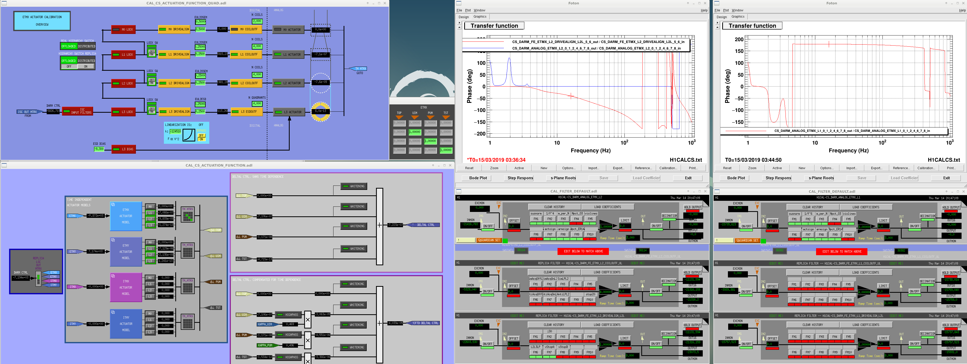
OTOH if you look at the calibration model actuation path, A1 and A2 are the product of three filter modules (DRIVEALIGN, COILOUTF and another one called ANALOG that represents the suspension response in analog world), output matrix that mixes L1 and L2 ANALOG output, and some digital gains. All of these are shown in the 2nd attachment (all gains are positive in this screenshot which represent the status now, but when Craig "flipped the L1 gain" H1:CAL-CS_DARM_ANALOG_ETMX_L1_GAIN was set to -1 rather than 1).
As shown in foton and filter screen shot, ETMX L2 drivealign L2L is -40.7deg at 16Hz, H1:CAL-CS_DARM_FE_ETMX_L2_COILOUTF is just a pass through, and ANALOG_ETMX_L2 was 0 deg, so the total is -40.7deg.
L1 drivealign is a pass through, coiloutf is a pass through, and ANALOG_ETMX_L1 is about 179.1 deg at 16Hz, so the total is 179.1deg.
phase(TF1)=179.1deg
phase(TF2)=-40.7deg
phase(TF1/TF2)=219.8 deg (model).
Comparing the model and measurement, it seems to agree well, which means that the sign of L1 path relative to L2 is correct now.
(But it was not the case when H1:CAL-CS_DARM_ANALOG_ETMX_L1_GAIN was set to -1 because phase(TF1) in the model was -0.9deg due to additional 180 degrees, so the model didn't make sense.)
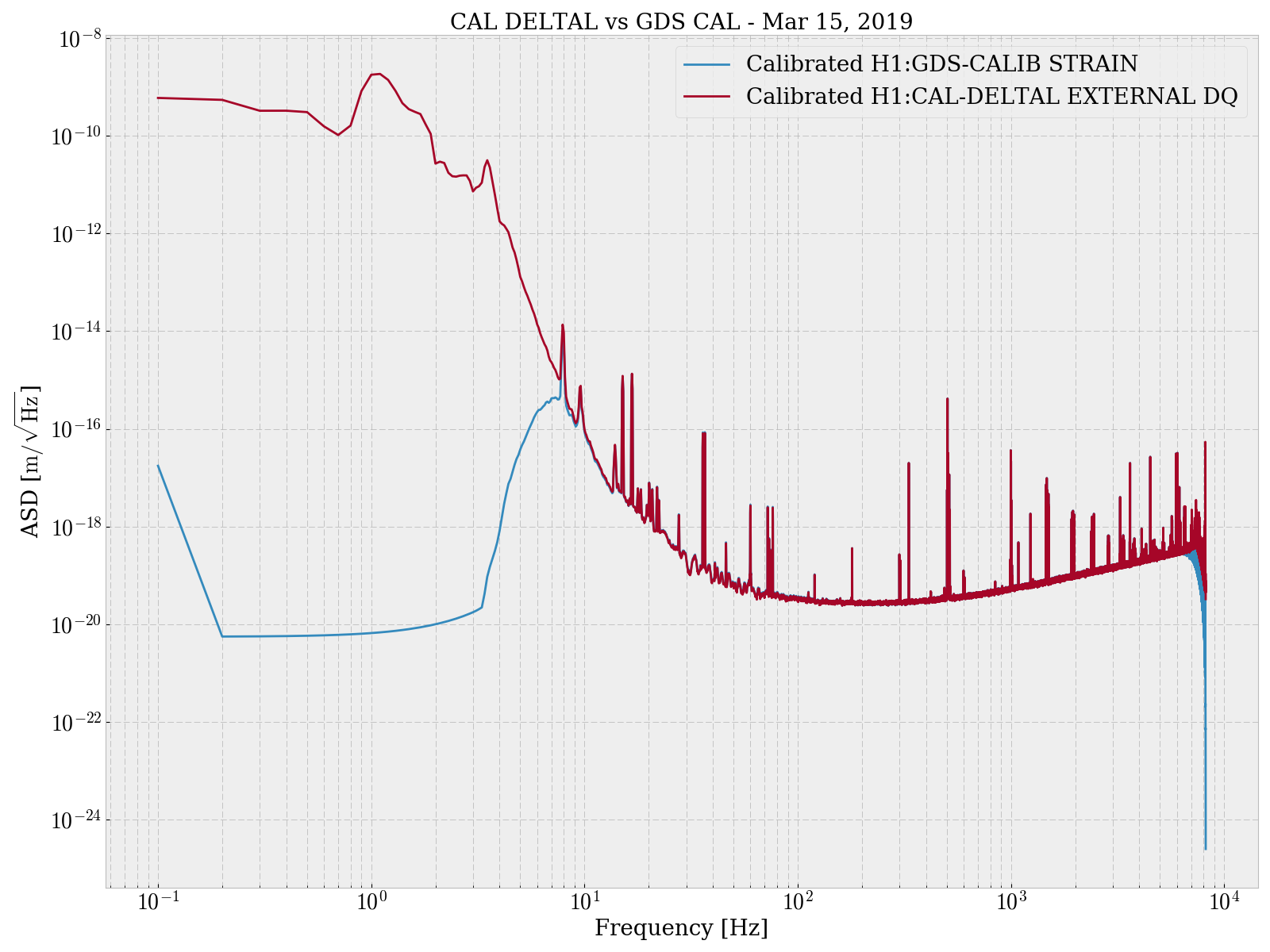
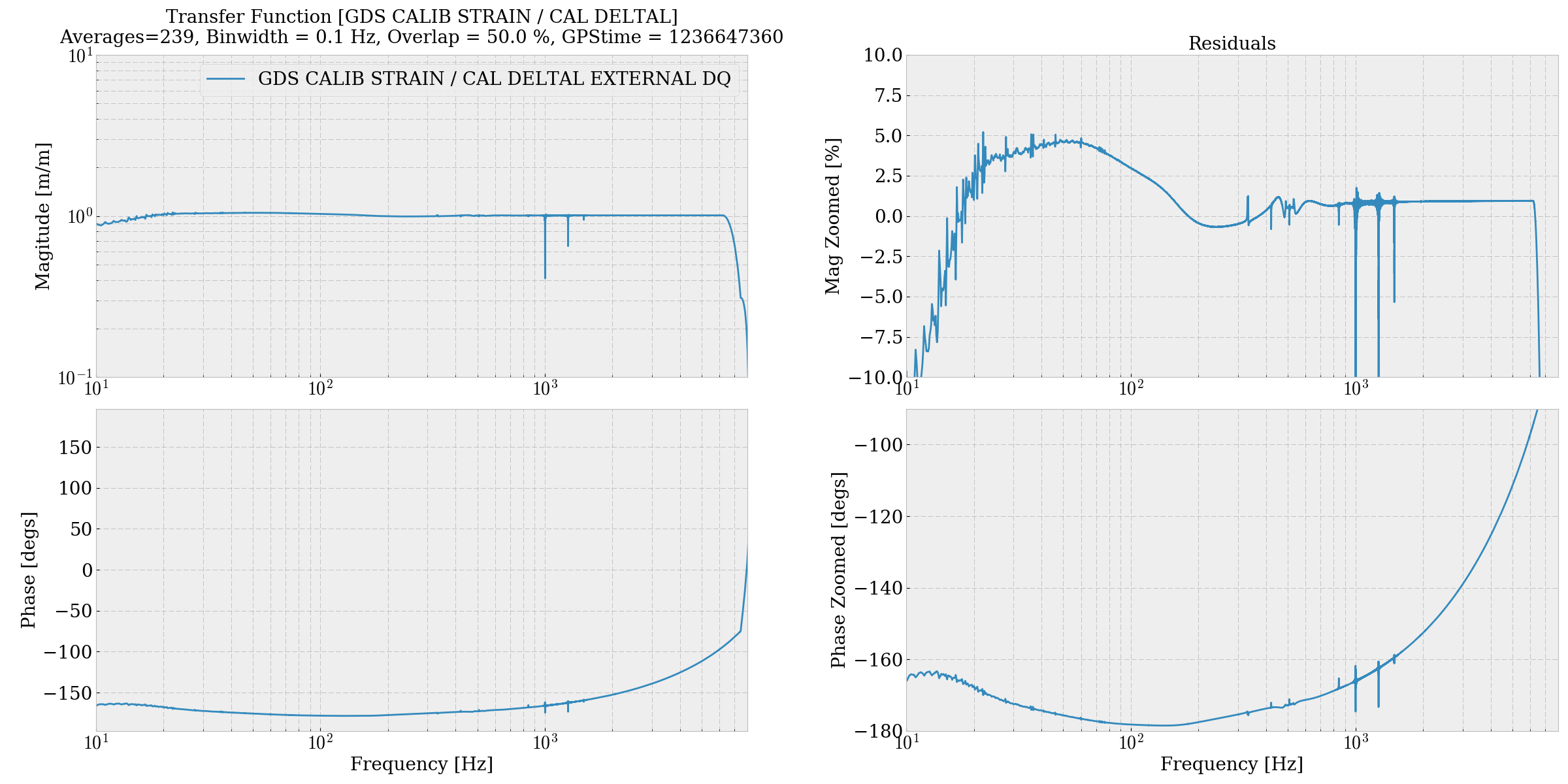
Here is a comparison of the ASD, TF, and uncalibrated time series between GDS CALIB STRAIN and CAL DELTAL EXTERNAL.

The calibration applied to GDS CALIB STRAIN was just a multiplication by L = 3994.5 m.  The calibration applied to CAL DELTAL EXTERNAL is attached as .txt: this is what is in the DARM FOM currently.  These calibrations are applied to both the ASD and TF plot.
There appears to be around -170 degrees between GDS CALIB STRAIN / CAL DELTAL EXTERNAL DQ.

Oh sorry I attached slightly wrong file for sign-flip measurement. This is what I wanted to show.
Test of DTT calibration for DELTAL (suspicious).
Since there was still some possibility that the DTT calibration was wrong, I asked JoeB to do the same measurement using LLO template but somehow he couldn't reliably pull the H1 data when he tried. I did it on my own following JoeB's advice.
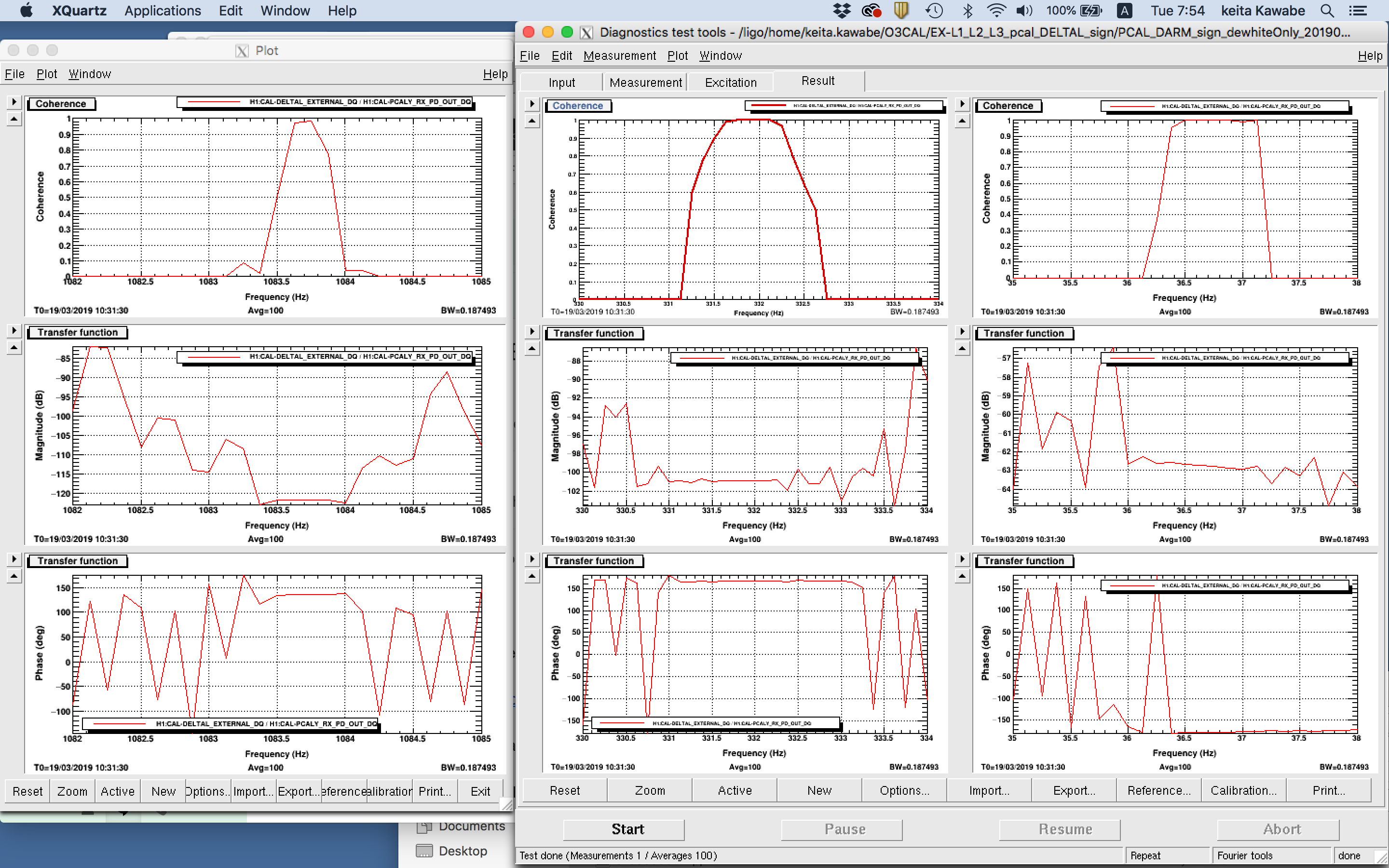
I removed the DTT calibration from LHO DARM FOM template, and put 6 pairs of [z,p]=[30,0.3] as dewhitening. This should be good enough. For Pcal I didn't change anything from my previous measurement (i.e. remove DTT calibration which was two poles at 1Hz, and just used the gain of 1 as the calibration).
The result shows that the sign was actually correct before we put the overall sign flip in (first attachment), and got incorrect after the overall sign flip (second).
The DTT templates were saved as
/ligo/home/keita.kawabe/O3CAL/EX-L1_L2_L3_pcal_DELTAL_sign/PCAL_DARM_sign_dewhiteOnly_20190313235002.xml
/ligo/home/keita.kawabe/O3CAL/EX-L1_L2_L3_pcal_DELTAL_sign/PCAL_DARM_sign_dewhiteOnly_20190319103130.xml
I have no idea how DTT template calibration is officially generated, so this could still be an intended behavior. Investigation continues.