Georgia, Daniel, Sheila
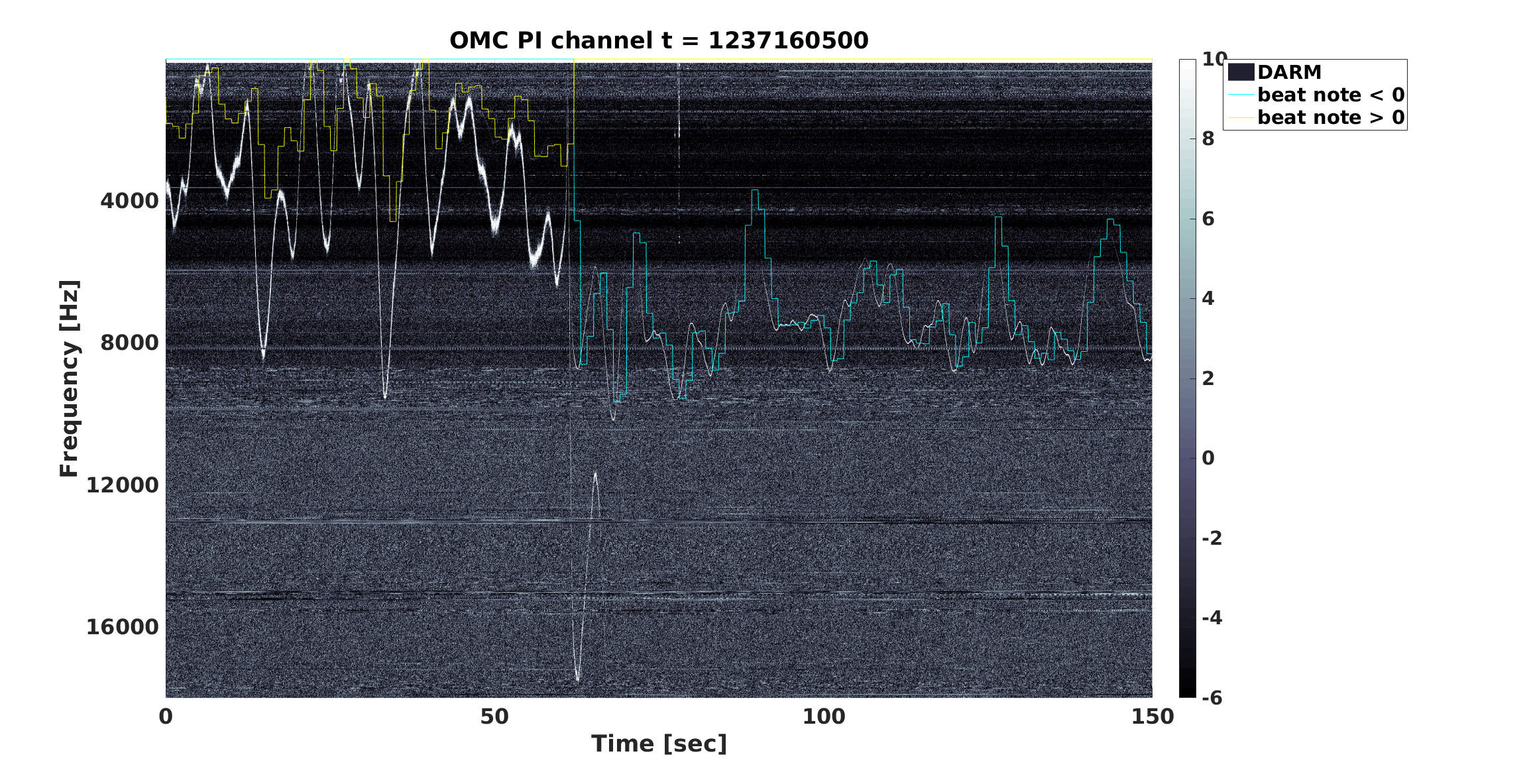
Since Daniel got the IMC VCO feedforward to the squeezer working (47675) we repeated the test we tried the other night of unlocking the LO loop to look for backscatter and seeding peaks. This was a follow up on the acoustic coupling investigations in 47551. This is similar to the test done at LLO 43881. Here, the pick off for the squeezer laser locking fiber is from the ref cav path (shifted by 2*IMC VCO frequency from IFO carrier), while LLO gets the pick for the squeezer laser locking from somewhere else that is at the same frequency as the light injected into the IMC. Even with the feedforward from the IMC VCO to the squeezer VCO our squeezer laser is still moving relative to the IFO carrier, so Georgia made some spectrograms with the frequency H1:SQZ-FREQ_SQZBEATVSDOUBLEPSLVCO overlaid on it. (Second attachment).
Power estimates:
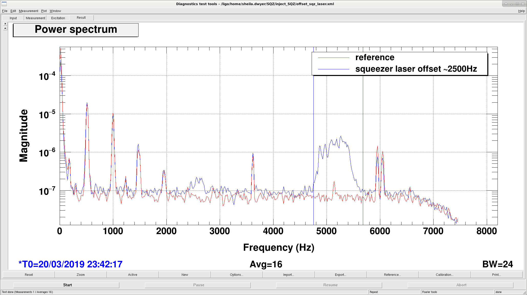
The first attached screenshot shows the two lumps in the DCPD spectrum caused by seeding (the smaller peak at the laser frequency offset) and the larger peak is the idler generated at the difference frequency between the green pump at twice the squeezer laser frequency and the interferometer carrier scattered into the OPO. The rms area in the backscatter lump is 39nA, while the area of the reference in this frequency band is 2.2nA, considering the 20mA carrier on the DCPDs and the responsivity of 0.858A/W this means that we had 89 fW of backscattered idler reaching the DCPDs. The ratio of the amplitude of the idler to IFO carrier is x, which is 1-1/sqrt(nonlinear gain) (page 189) , since we have a non linear gain of ~2.3, we should have ~770 fW of scattered light from the OPO reaching the DCPDs at the interferometer carrier frequency.
We collected measurements that can be used to predict the amount of scattered power reaching the OPO in 46099, we can expect about 23nW of carrier to reach the OPO, so the power reflectivity of the OPO is roughly 3.3e-5. This is similar to what Sheon Chua measured, which was 41dB of backscatter isolation. The amount of scattered light power we are seeing is roughly consistent with our expectations.
The seeding peak is much smaller; the rms area of the peak with the reference subtracted in quadrature is 2.6nA, which implies 0.4 fW of seeding power reaching the DCPDs.
Noise coupling paths:
Although the amount of scattered light is about what we expected, the acoustic noise coupling that we saw from ISCT6 in 47551 is too close to DARM. We thought about three coupling mechanisms:
- The pump laser picks up frequency noise on ISCT6, and the OPO locking loop imposes this noise on the OPO length through the OPO PZT. The scattered light circulating in the OPO will pick up a phase shift from this, which is amplified by the number of trips the scattered light takes in the cavity.
- The phase noise on the pump is imprinted on the scattered light through the non linear interaction. This also happens to the seed beam, but since there is so much more backscatter than seeding the backscatter would be the dominant coupling. This noise coupling mechanism would depend on the non-linear gain in the OPO. (Which we did see some evidence for in 47551) The CLF and LO locking loops together are meant to lock the phase of the green light in the OPO to the phase of the interferometer carrier light, so changing the gain in these loops could have an impact on this coupling. We did not see a change in the coupling when we changed the gain of the LO loop, but we did see a change in the noise when we increased the gain in the CLF loop. This may make sense because the LO loop has a higher bandwidth than the CLF loop, so increasing it's gain doesn't increase the suppression of the audio phase fluctuations between the pump and the carrier. This seems like the most likely explanation given the observations in 47551.
- You could imagine that the noise on the seed field is much larger than the noise on the scattered field for some reason, but this is ruled out by the test we did in 47551 where the acoustic noise coupling didn't depend on the power in the CLF.
Aside about frequencies reported on the squeezer frequency screen (screenshot attached):
- The light from the ref cav fiber is above the IFO carrier frequency by twice the IMC VCO Frequency (f_rc = f_car +2f_imc)
- The beat note is measured by H1:SQZ-FREQ_SQZBEAT, we keep the squeezer laser below the ref cav light frequency (f_beat = f_rc - f_sl)
- The TTFSS moves the squeezer laser so that the beatnote is twice the squeezer VCO Frequency H1:SQZ-VCO_FREQUENCY which I think is the same as H1:SQZ-FREQ_SQZVCO
- The difference between the beatnote frequency and twice the squeezer VCO frequency is calculated in the timing system as H1:SQZ-FREQ_SQZBEATVSDOUBLESQZVCO, which should be 0 when the TTFSS is locked.
- The difference between the squeezer VCO and the IMC VCO is half the frequency difference between the squeezer laser and the interferometer carrier beam, H1:SQZ-FREQ_SQZVCOVSPSLVCO, based on readbacks of both VCOs
- The last line on this screen is H1:SQZ-FREQ_SQZBEATVSDOUBLEPSLVCO which is the difference between the squeezer laser and the interferometer carrier, calculated as Delta = f_beat - 2* f_imc, This is what Georgia has overlaid on her plot in blue and yellow.