Nutsinee Daniel
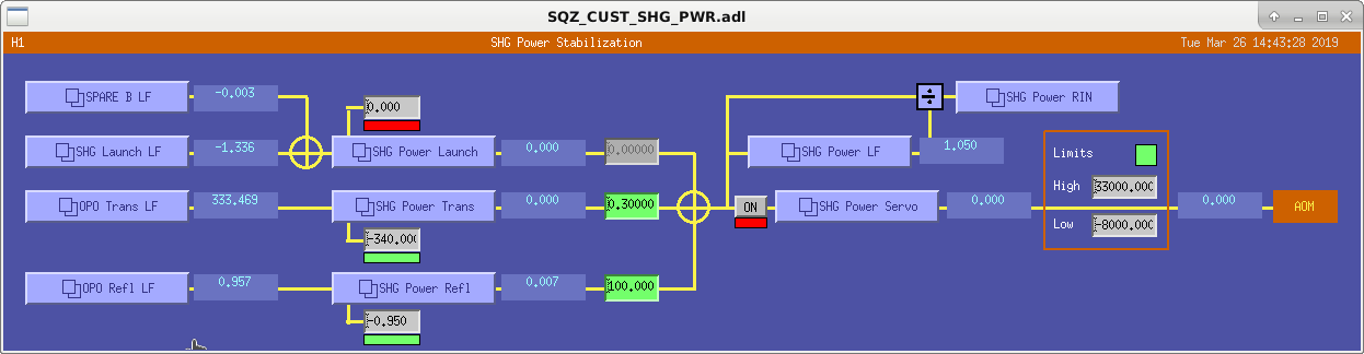
Asymmetric limits have been added to the green power servo to allow for lower power but limit the injected power to 20mW.
A new photodetector, Femto LCA-S-400K-SI-FST, has been installed in the OPO transmitted path.
The screenshot shows the updated servo screen.
Plot 1 shows the transfer function of this servo using the OPO reflected power (blue) and the OPO transmitted power (red).
Plot 2 shows the spectra of the OPO transmitted and reflected powers for servo off & optimized PDH offset (green), old PDH offset (blue), servo on using the transmitted power (brown), using reflected power (red) and the dark noise (black).
Plot 3 shows the coherence.

Earlier today I found that we have been operating with an offset in the common path. This offset was there because at the time when we swapped scheme the I error signal wouldn't go to 0 when OPO was locked (hence the offset was to zero this error signal). But only this morning I realized it caused a big offset in OPO refl and trans signal and we have been operating at the side of the fringe (and thus we have been sensitive to the OPO length noise, see 1.4 kHz peak, blue plot). Daniel found a new/better offset (1.45, was -4.125) which results in 11% more transmission and 16% less reflection from the OPO. And the OPO length noise diminished (red plot).