Craig Dan Danny Georgia + Jeff B and Ed
Over the past week we've taken a couple of steps with the ring heaters, trying to find a more optimal TCS configuration for 35 W input power. Craig and Dan previously set up the AWG_LINES guardian to inject frequency noise, intensity noise, and 9MHz RIN lines. I wrote a quick matlab script to demodulate these lines, and have made some plots of how these couplings change over time with the ring heater steps. This is building on an ipython notebook Dan had already written, but it cuts the data into chunks so it doesn't require the cluster to run. This work is ongoing but I'm posting what we've got so far.
It's a bit loose for now, but for interested TCS'ers, script lives here:
/ligo/home/georgia.mansell/TCS/AwgLineDemod/plotTCSDemodLines.m
20190325 - Common decrease in ITM RH power
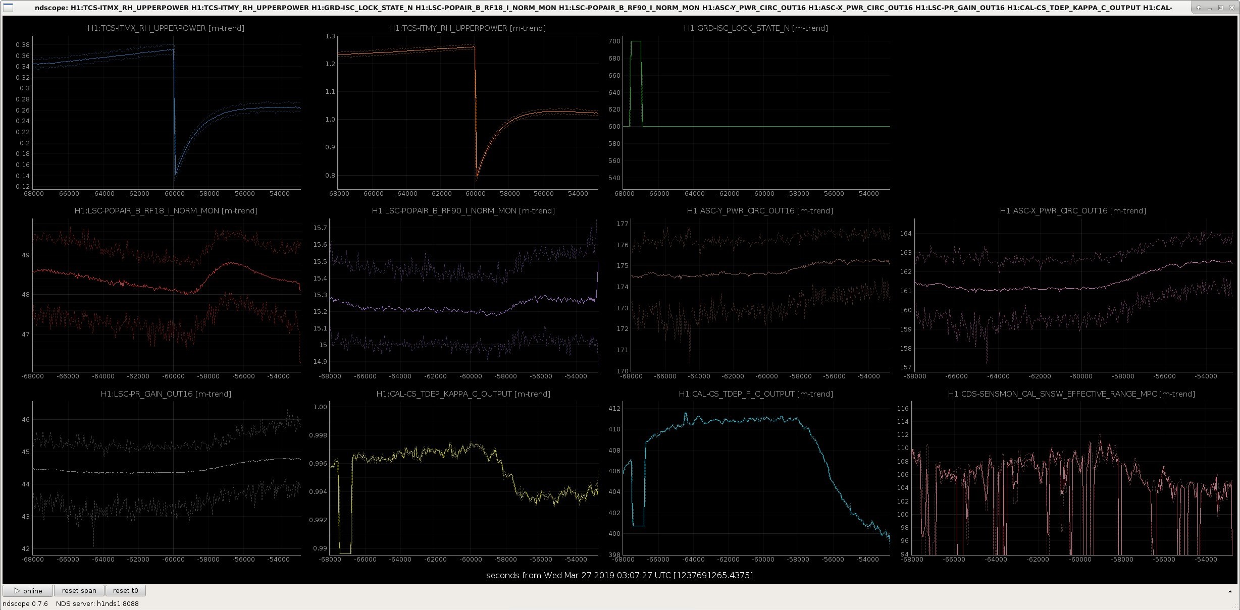
On Monday Jenne decreased the ITM ring heaters in common by ~250 mW. She saw:
- improvements in POP_RF18, POP_RF90, circulating power, and power recycling gain
- a decrease in the cavity pole and Kappa_C
- ~5 Mpc decrease in the BNS range
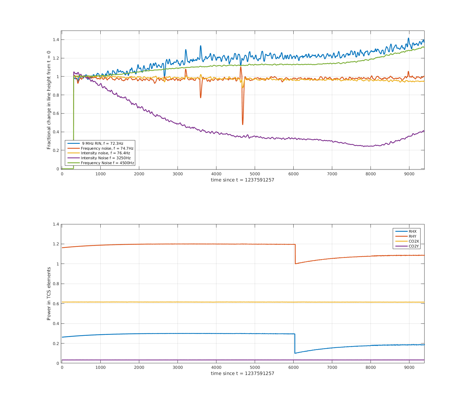
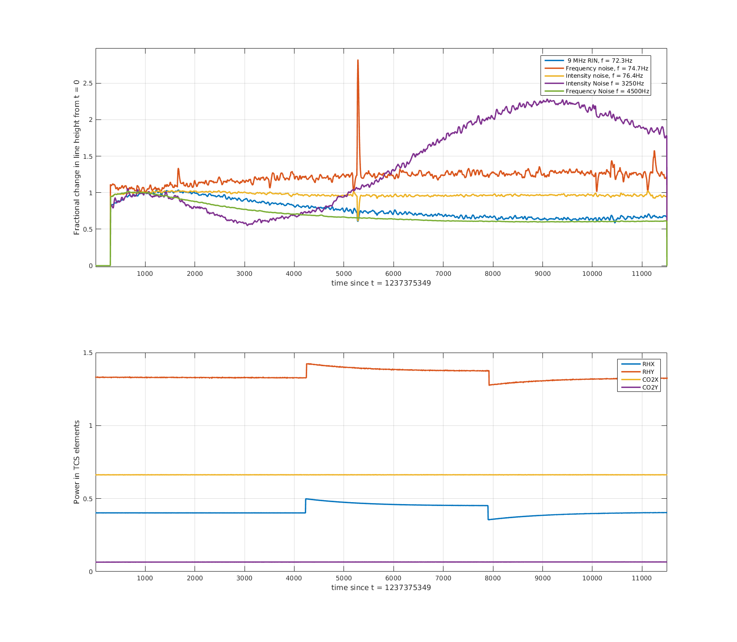
The first attachment shows an ndscope of the diagnostics, as well as the ring heater powers. The second attachment shows the demodulated lines, normalised to t ~ 700 s (sorry it's a bit dodgey for now). The time axis starts just after the first step down, at roughly the same time as the cursor in the first attachment (the lines were not on before this time), the lower plot shows the ring heater set_upper_power, which is controled by Danny's ring heater guardian.
The interferometer was well thermalised before this change, having been locked for 19 hours. Things to note: the coupling of the 9 MHz line, and high-frequency frequency noise appears to grow with this ring heater step. The high-frequency intensity noise coupling drops, though seems to turn back up towards the end - maybe we overshot some minimum coupling? The ring heater time constant is very slow. The frequency and intensity lines in the bucket seem unaffected.
20190325 - Differential decrease in ITM RH power
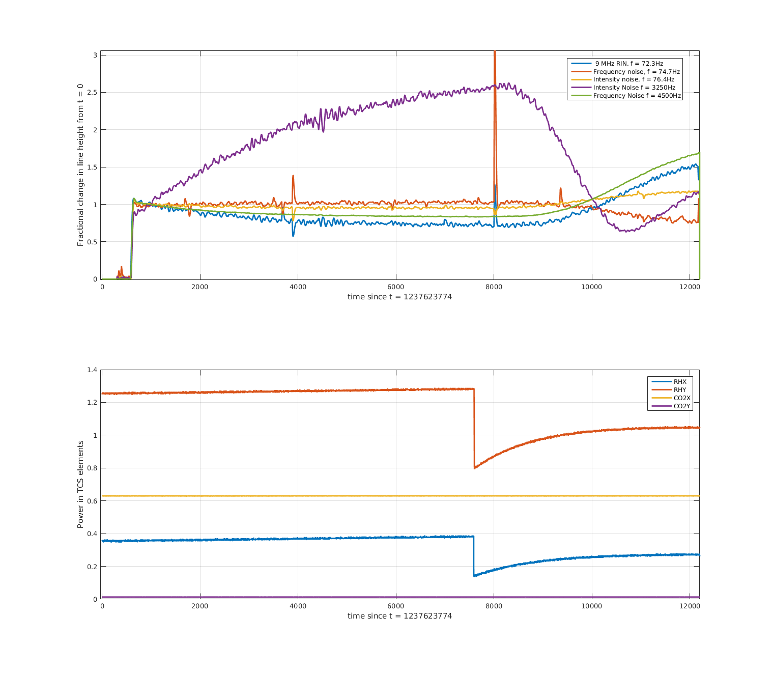
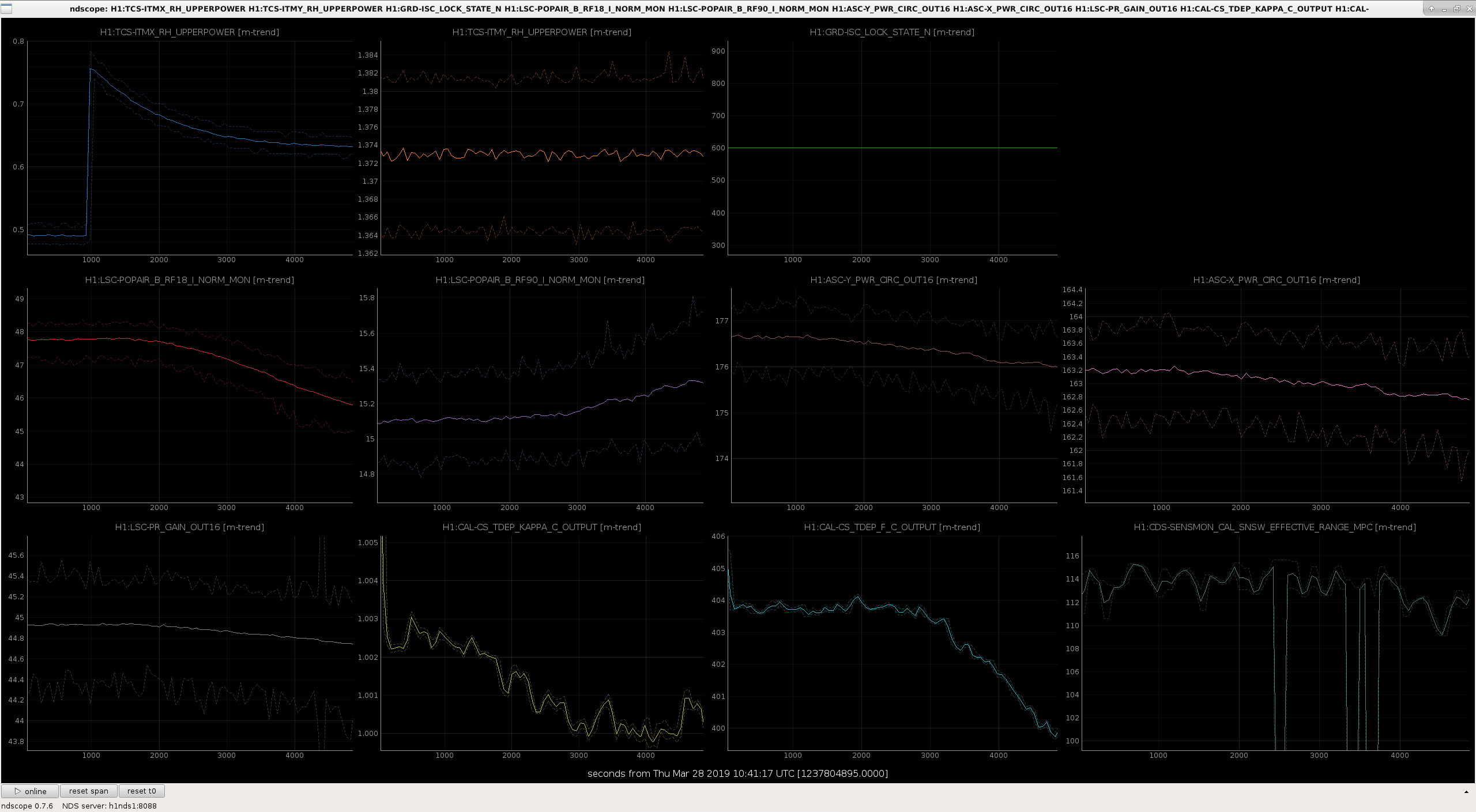
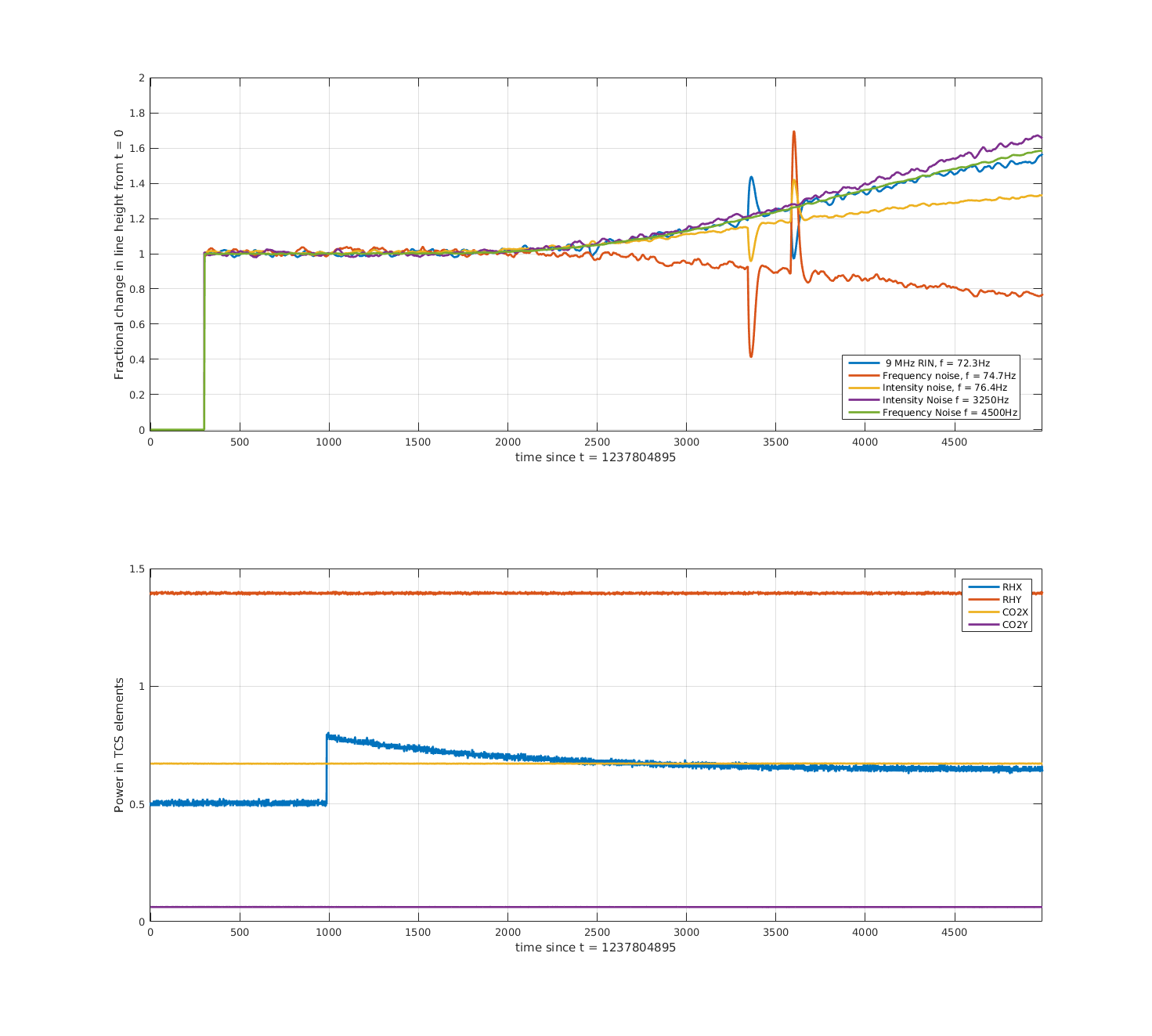
Later the same night, we tried a slightly differential step down in the ring heaters, lowering ITMX by ~0.1W and ITMY by ~0.26W. We see similar behaviour in our diagnostics (third attachment), increase in RF18 and circulating power, decrease in the f_c and range. Note that this step was taken sooner after locking, and that the interferometer was still thermalising. The fourth attachment shows the demodulated lines. Changes before the step at t~7500 are due to the thermalisation of the interferometer. After the ring heater step, the high frequency intensity noise again takes a dip (with a pretty fast time constant), while high-frequency frequency noise and RF9 increase. Craig noted that the high frequency line and the 9MHz RIN line (at 72.3 Hz) are moving together. With this step intensity noise in the bucket seems to rise, and frequency noise in the bucket seems improved.
20190323 - Common increase in ITM RH power, followed by decrease
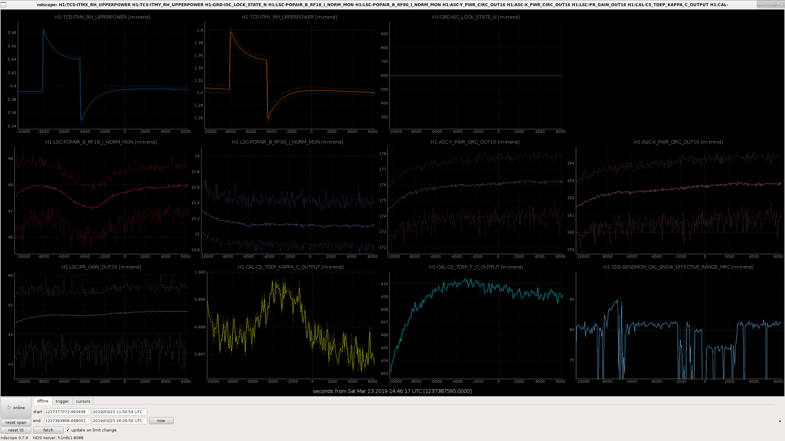
On Friday night Danny and Ed took a 0.1 W common increase in the ring heater power. Note earlier that night we had seen that a 0.5 W increase on ITMY only caused POP_RF18 to plummet potentially causing a lockloss. During this step the interferometer was still thermalising, see for example RF90 (purple trace in fifth attachment) dropping before the ring heater step. I originally got excited to see the range increase but probably that was due to some squeezer shenanigans happening at the same time? With the increase in power RF18 looks like it drops a little, but other diagnostics don't show much. I think the demodulated lines (sixth attachment) are dominated by the thermalising IFO.
Tonight (@ 10:57:43 UTC) we have tried increasing the power on ITMX ring heater only, we requested 0.8 W from the filter input, where nominally it is 0.5 W. If future operators or commissioners would like to return this value to nominal after lockloss (eg if ASC is problematic), this can be done in the command line:
caput H1:TCS-ITMX_RH_INVERSE_FILTER_IN 0.5

The new custom mask has not been installed as far as I know. The testing, according to the mask guardian, has been done with the central mask.
The results from last night's RH_X step up by ~0.15W:
- POPAIR_B_RF18 went down, RF90 went up (bad) (red and purple traces of first attachment)
- Circulating power decreased (brown, pink, grey traces)
- Kappa_c and cavity pole decreased (yellow, cyan traces)
- Possible reduction in BNS range
- Coupling of 4/5 lines (RF9 RIN, high-and-low-frequency intensity noise, and high frequency intensity noise) got worse (second attachment)
- Frequency noise in the bucket improved.
Overall, not good.
I've made the same plots of diagnostics and demodulated lines for some of the CO2 steps done last week by Dan and co.
20190319 - CO2X steps up
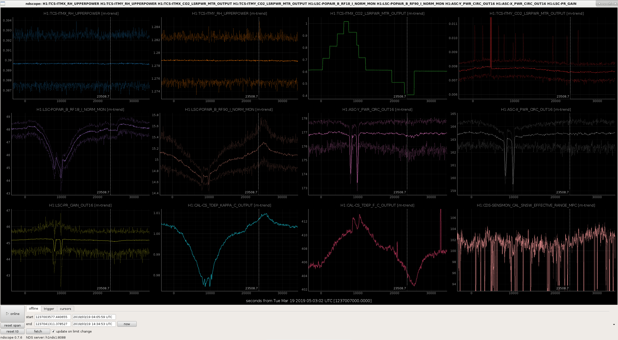
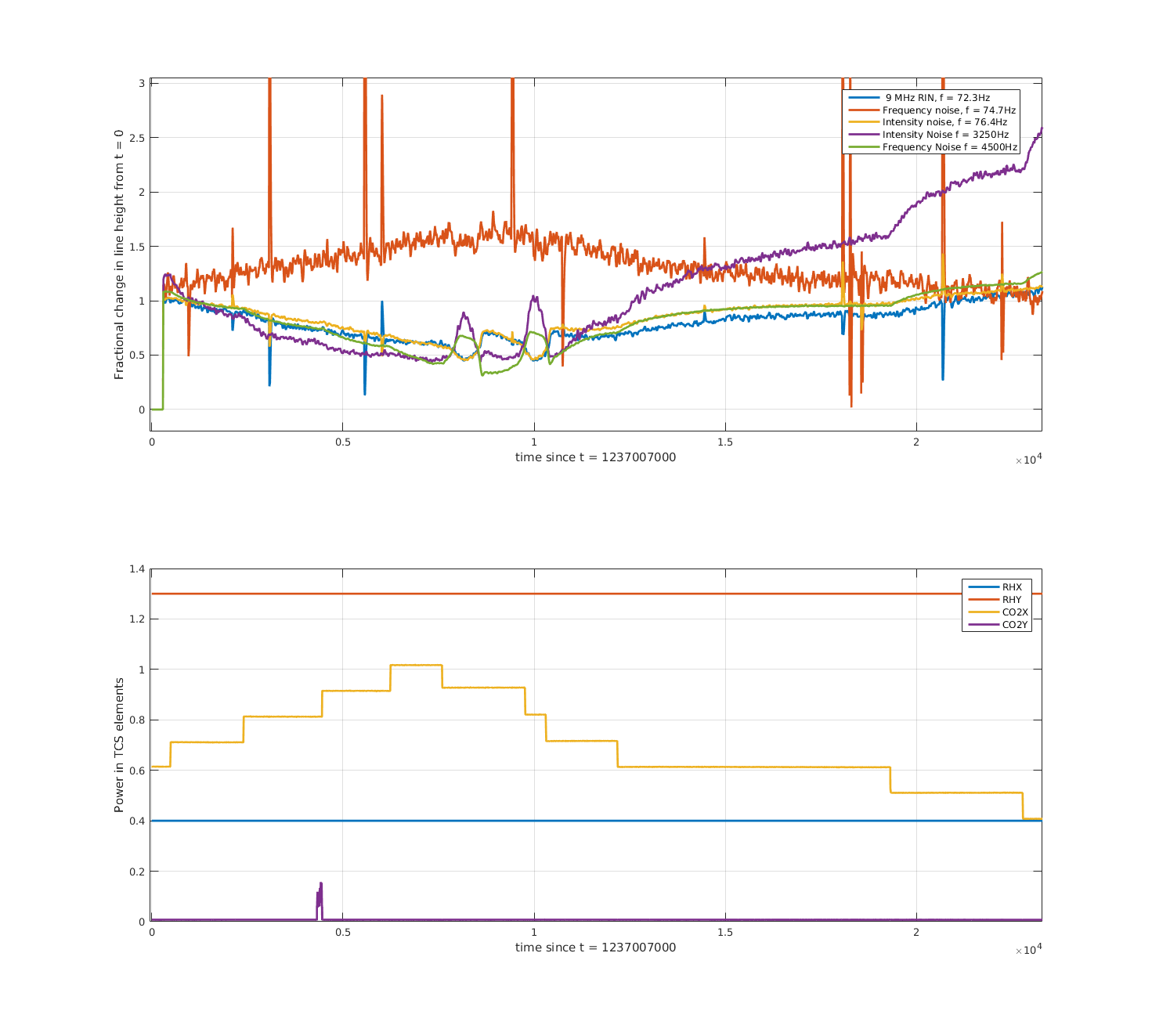
Most of the analysis for this one was already done by Dan (alog 47658). First attachment shows the diagnostics, second attachment shows the demodulated lines. Some things to note
- RF18 got worse but RF90 got better?
- Cavity pole increased (all of our other TCS tunings so far have reduced the cavity pole)
- The 9MHz RIN (blue), high-and-low-frequency intensity noise coupling (purple, yellow), and high-frequency frequency noise (green) coupling improved, frequency noise coupling in the bucket (red) worsened.
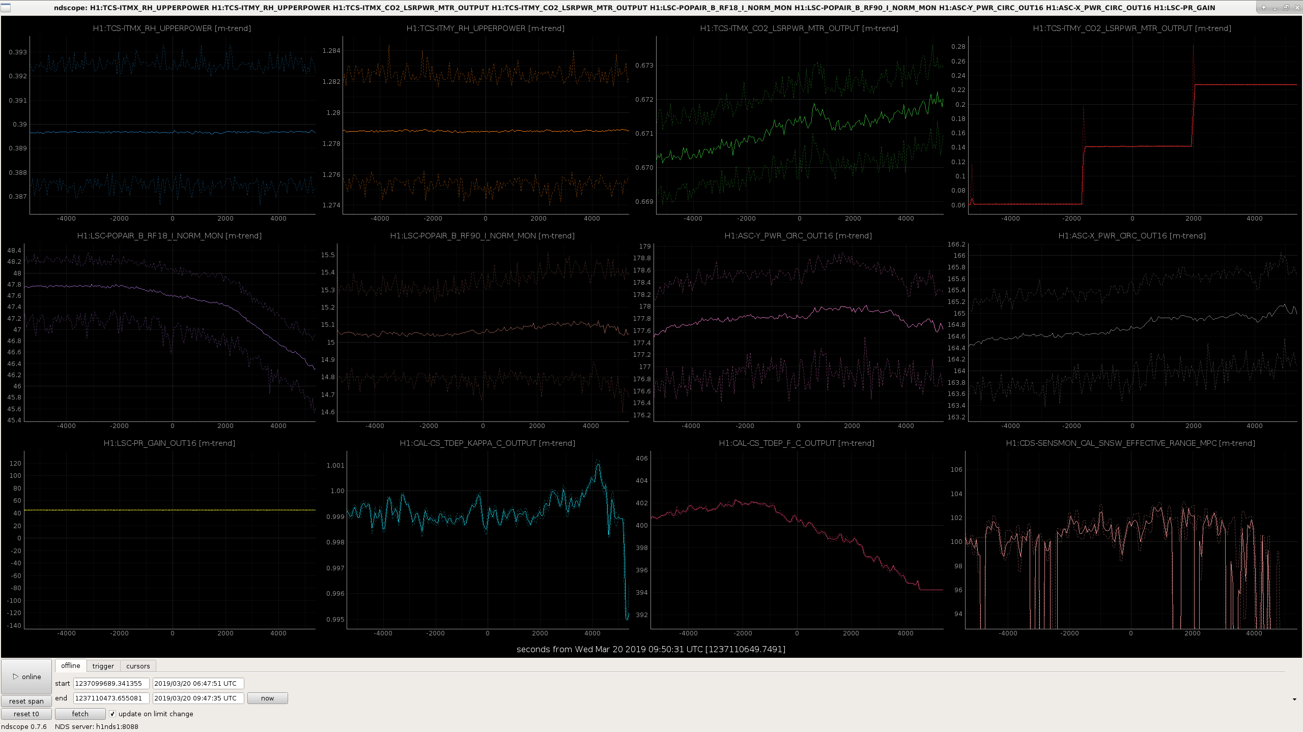
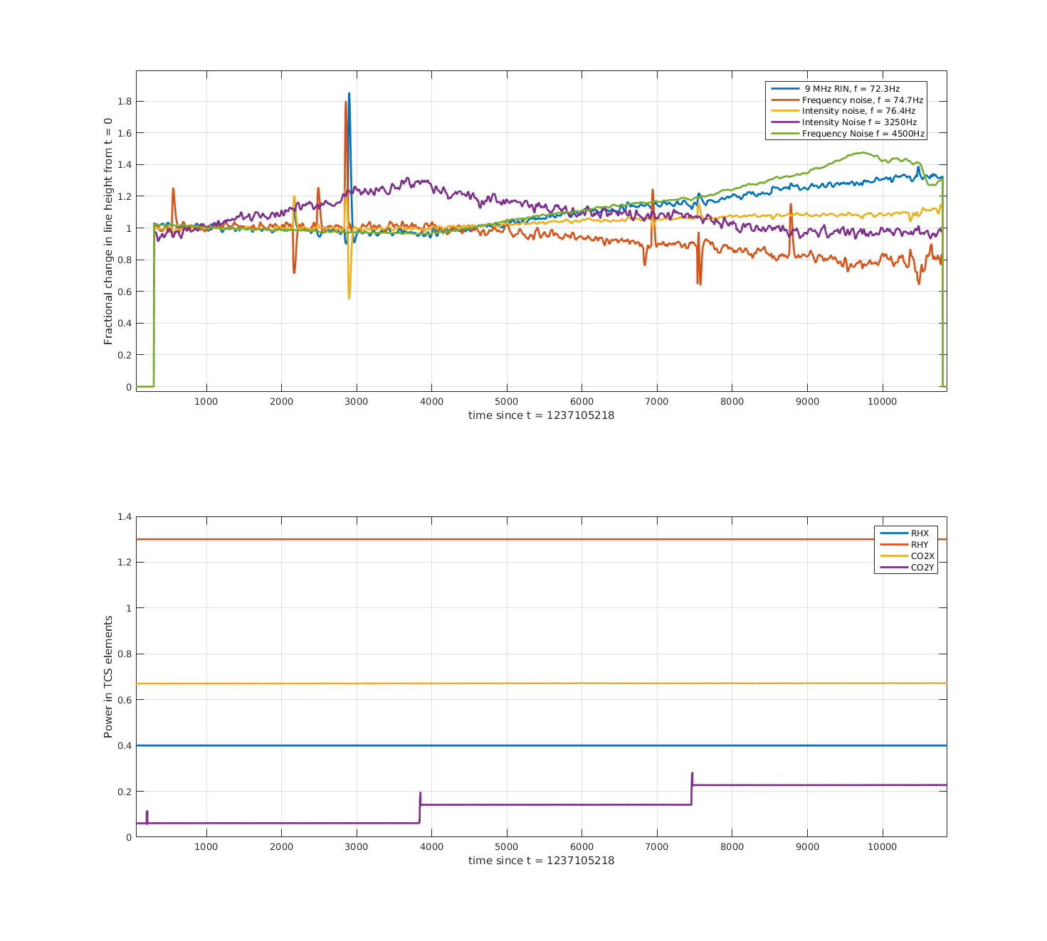
20190320 - CO2Y steps up with point-absorber-notching mask
We did two tests around 20190320/21 with CO2Y power increasing, one with and one without the point absorber mask. The results were pretty similar. Third and fourth attachments are diagnostics and lines with the mask was one (the ifo had better thermalised for this test so the results are less confusing)
- RF18 and 90 got worse
- circulating power.... hard to tell
- cavity pole decreased, kappa_c increased
- range maybe improved?
- 9MHz RIN, high-frequency frequency noise, and low-frequency intensity noise coupling got worse; while high-frequency intensity noise and low-frequency frequency noise improved.
Based on all these test so far it's not obvious to me what combination of TCS settings we need to get the improvement we'd expect from out 30 - 35 W input power increase.
Was the second version of the CO2Y mask installed for this test? The first version is no longer valid due to the movement of the IFO beam.