Sheila, Daniel, Nutsinee
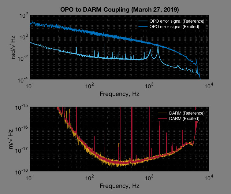
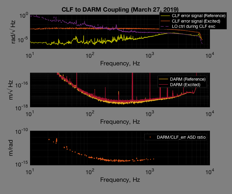
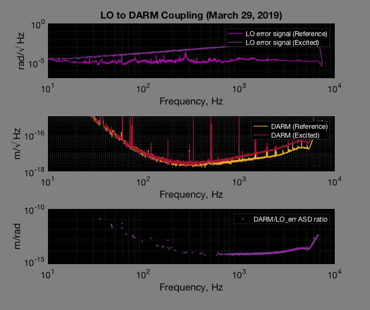
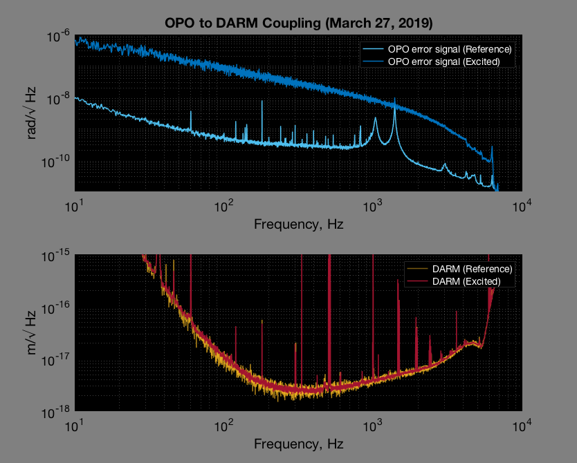
We injected broad band noise into DARM through various point in SQZ system: OPO, CLF, and LO common mode board. All injections were made after the boosts (exc A on the common mode board). Only CLF and LO injections showed up in DARM. We increased OPO error signal by two orders of magnitude and didn't see much (if anything at all).
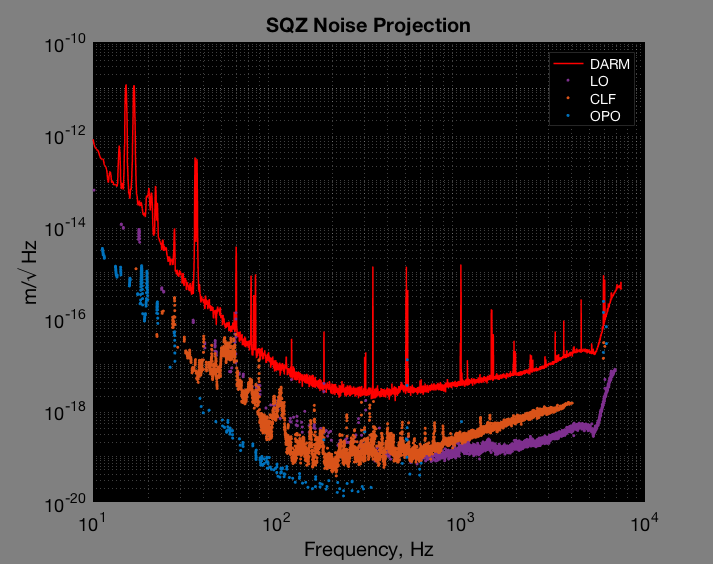
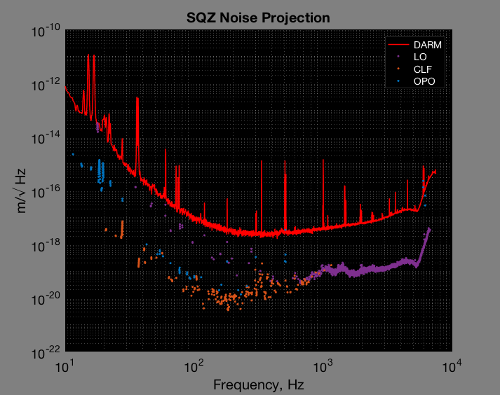
Only data points where witnesses (LO, CLF, OPO) and DARM sees a factor of 1.5 increase during injections get plotted. The projected ambient SQZ noise is calculated using:
ambient = witness_ref.* ( sqrt(DARM_exc.^2-DARM_ref.^2)./ sqrt(witness_exc.^2-witness_ref.^2) )
The m/rad of DARM/LO and DARM/CLF ASD ratio are only a factor of 2 different, this could suggest that wherever we inject (CLF or LO), the coupling mechanism is the same. Injecting noise through CLF added noise back to the pump laser as LO tries to suppress it (and inject that noise back to the laser). This results in the final phase difference between the green and the carrier, which is squeeze angle phase noise. On the other hand, injecting directly to LO the injection gets suppressed by the LO loop (UGF ~10kHz). The reason why CLF doesn't have much of a loop shape could be because CLF loop UGF is very low (<1kHz).
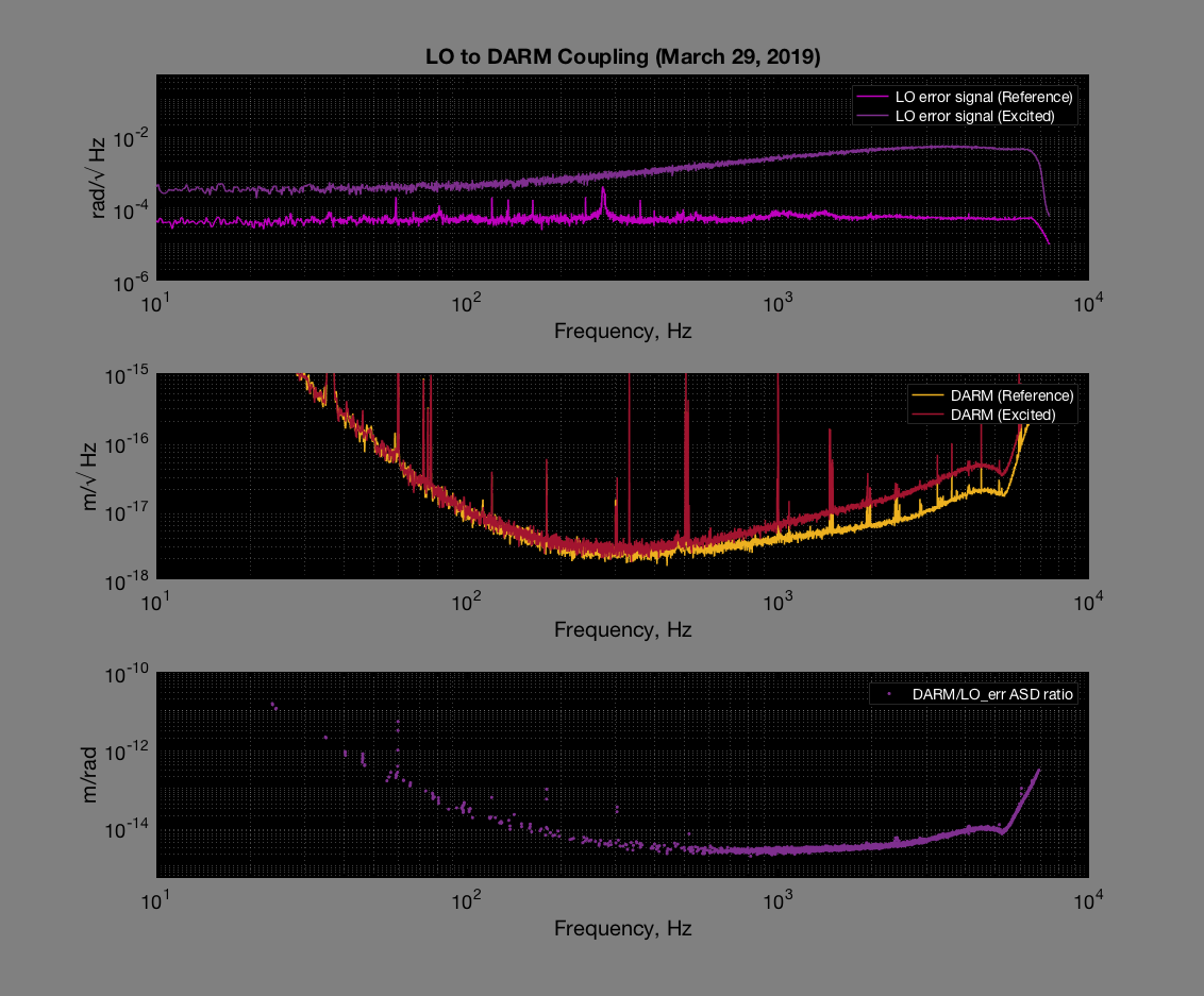
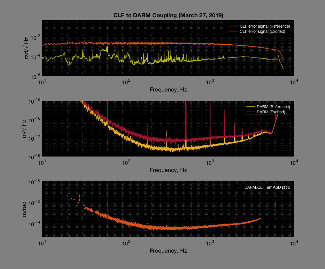
The best suspect for the coupling mechanism is the backscatter of the IFO beam (squeezer backscattered measurement) from the OPO. As CLF noise shows up in LO loop, LO tries to suppress it by sending the noisy control signal to the laser, which then makes the laser noisy, which makes the green pump noisy. The noisy green light gets inside the OPO, induced change in OPO crystal temperature which then induced length noise via dn/dT. When leakage IFO beam sees that, it brought back to OMC DCPD noisy signal which gets mixed in the clean carrier, causing the noise we saw.
Daniel, Nutsinee
The plots above have wrong calibration: here I attached a more properly calibrated one. All of them (OPO, CLF, LO) agree with the old plots taken from SR785 within a factor of 2.
We also found that during the CLF injection data used in the original plot we saturated the read back, so we found the time where things weren't saturated and used that data here.
Mystery: We don't get the same amount of LO per CLF excitation. These plots are calibrated in terms of sqz angle. CLF noise has been multiplied by a factor of 2. LO control signal is calibrated using VCO calibration.
I also changed DARM_exc/DARM_ref cutoff to a factor of 1.7.