Nutsinee Daniel
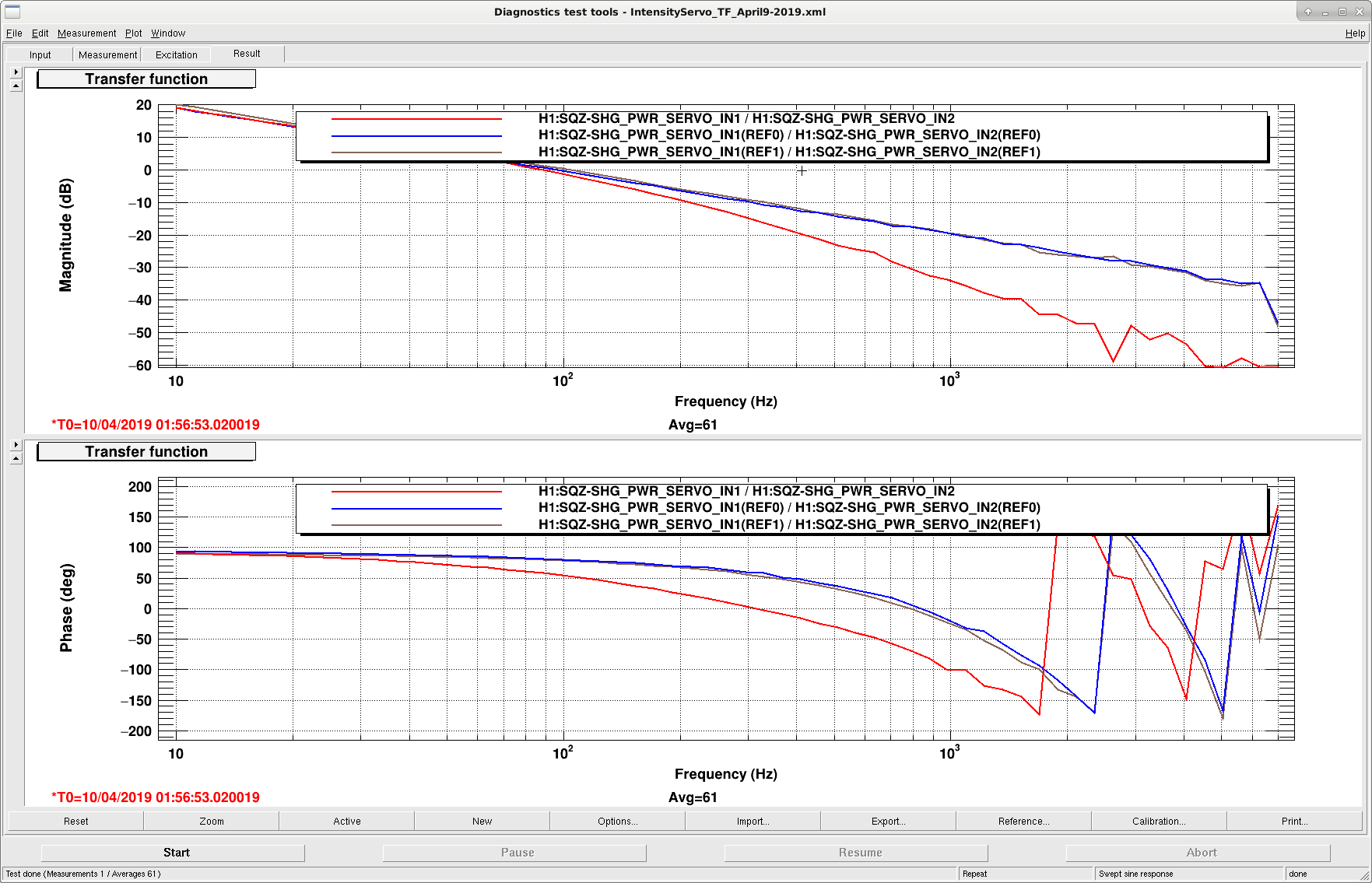
Plot 1 shows the open loop gain of the servo. Blue and brown represent the original TF using the OPO TRANS and REFL as error signals, respectively. Ugf is 100 Hz. The red curve is after we added a 200 Hz low pass filter to reduce high frequency noise.
Plot 2 shows the noise of the OPO TRANS and REFL photodetectors: the green curve shows the noise with the servo off, the red curve is with REFL as the error signal, the brown curve with TRANS as the error signal, and black represents the dark noise.
Plot 3: Coherence for the above spectra. There is a lot of uncorrelated noise below ~10 Hz.
The default error signal is now the transmitted power of the OPO. Nominal power in transmission is 325 nW, and 0.945 mW in reflection.

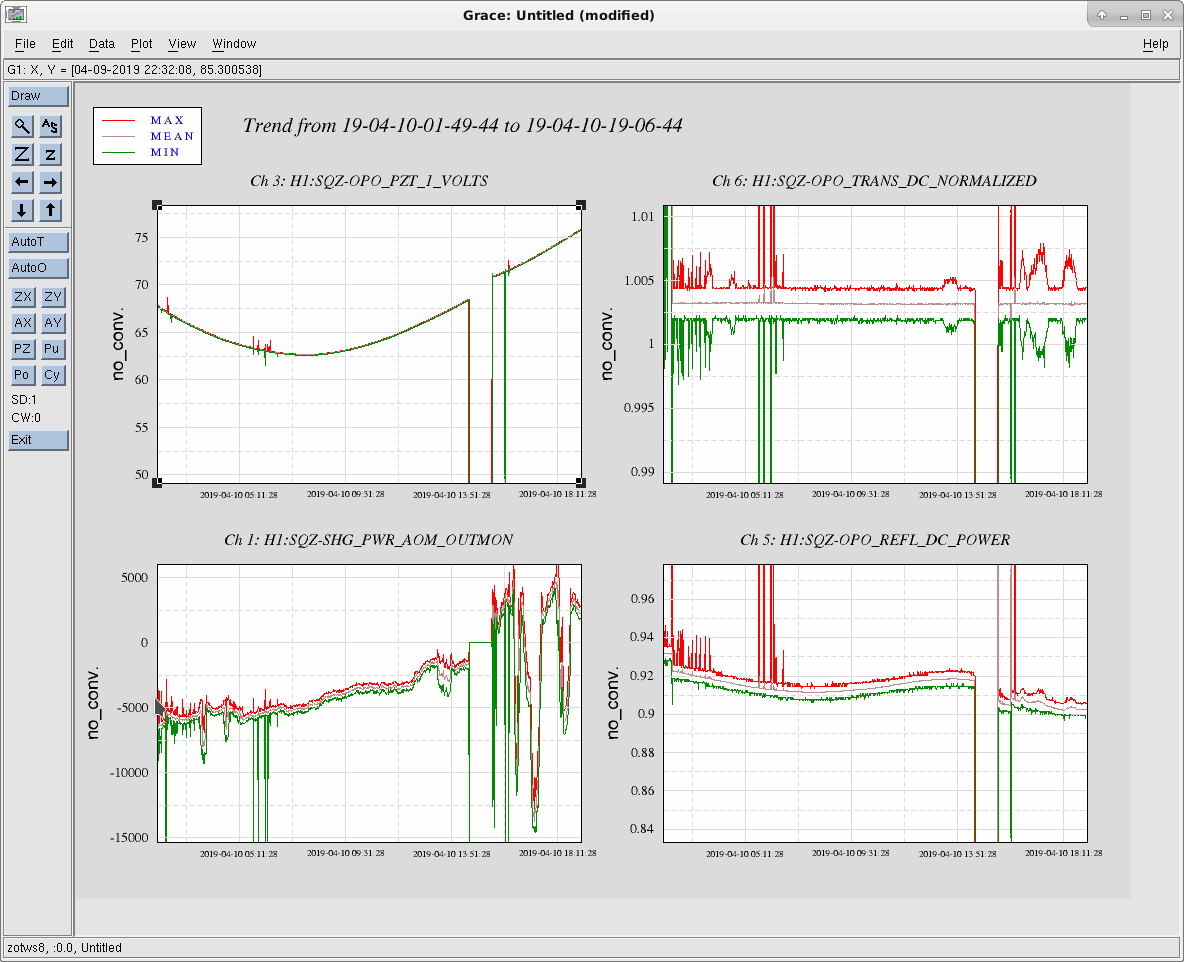
Not surprisingly, the transmitted power is much more stable now.