[Jenne, Sheila]
We have, as part of our commissioning and calibration efforts over the last few months, been a bit confused about our PUM ETMX actuator. Formerly, we only (in the calibration and commissioning contexts) modeled the direct length-to-length drives of our suspensions when looking at the DARM loop. Since the model that the calibration group uses does not include the extra terms that Sheila describes in alog 47982 and T1900148 (from angle to length), the measurements that the calibration group takes don't perfectly match their models, which they interpret as systematic uncertainty in part of the DARM actuator. This was confirmed with a test of driving length through both the usual drivealign matrix and in parallel through the test filter bank, with results summarized in Lilli's alog 47979.
Understanding the PUM actuator better will help the calibration group in lowering their systematic uncertainty, but also will help us understand why it has been such a struggle to boost our DARM loop offloading. See, for example, alogs 47164 and 47982 for some discussions of the boost.
The length motion of the test mass is (partly) due to actuation of the PUM: L3length = L2length drive * [L2_DriveAlignLength_to_Length * MechanicalCouplingL2length_to_L3length + L2_DriveAlignLength_to_Pitch * (MechanicalCouplingL2pitch_to_L3length + SpotPosition * MechanicalCouplingL2pitch_to_L2pitch)]
The traditionally modeled direct L2L coupling is the first purple term above, and I'm calling the second blue term L2P2L coupling for shorthand. After March 29th, we have set our L2_DriveAlignLength_to_Pitch term to zero to simplify our system. However, it would be nice to be able to turn the L2P filters back on in order to decouple our system more fully.
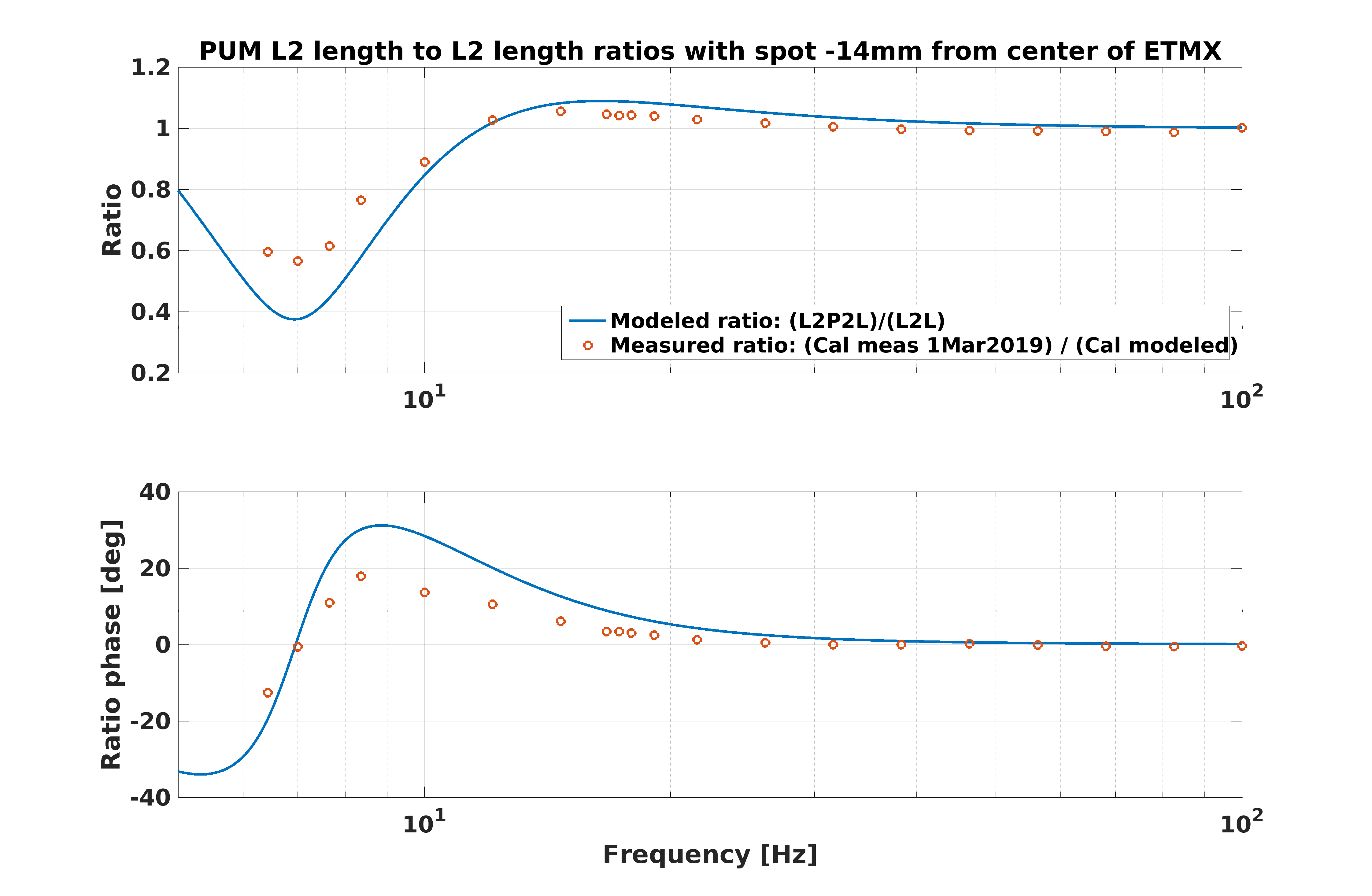
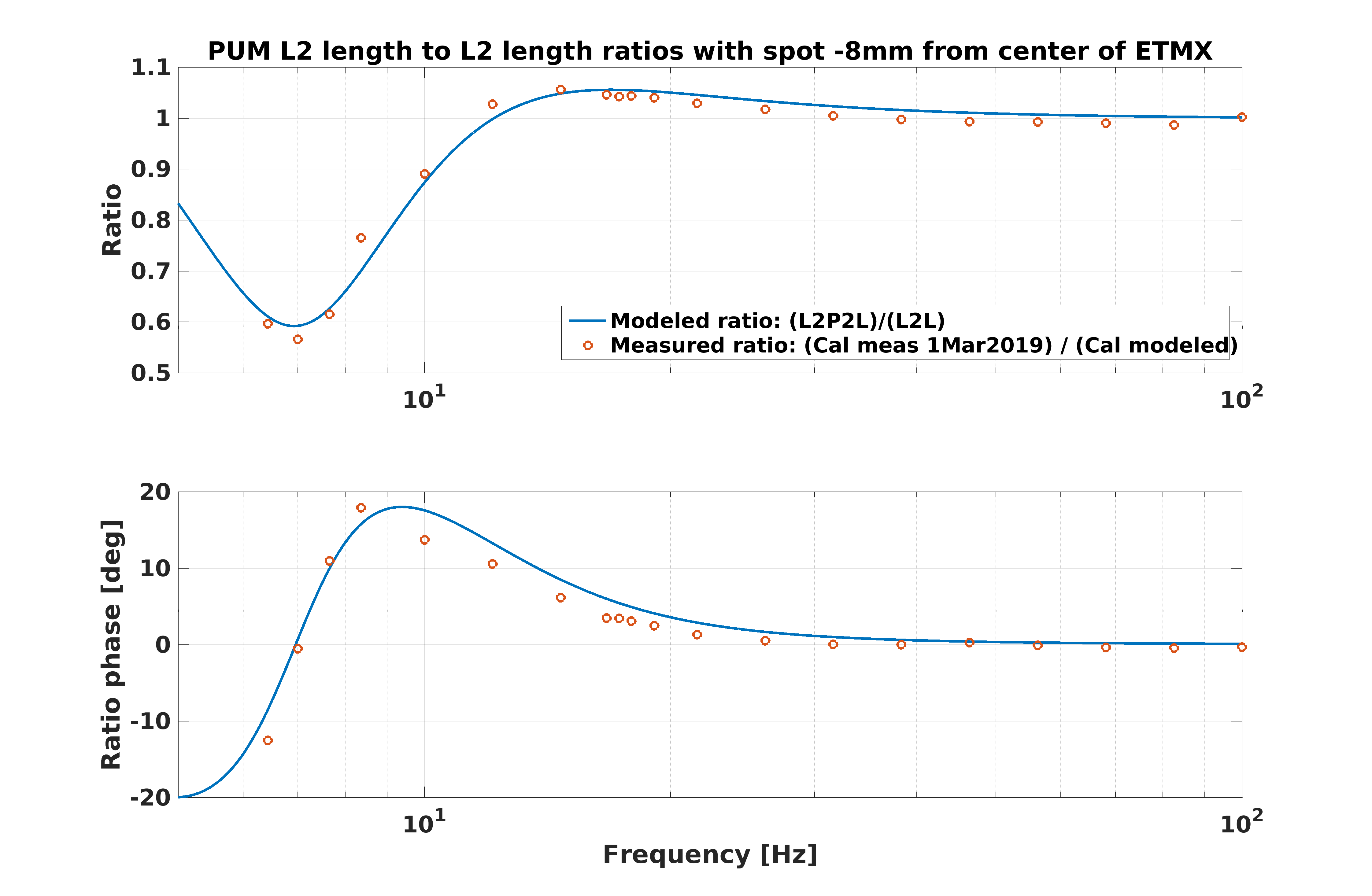
I have modeled the PUM actuator, including the "L2P2L" path, and it matches quite well with the calibration measurements of the PUM actuator from times before we turned off the L2A drivealign filters. This model does not take any yaw couplings, and also does not include any loops such as ASC. The matching comes up best if I set the spot position on the ETM at -8mm, rather than what we believe is the true value of -14mm at the time of this measurement (we're at -18mm now, but this is a slightly older measurement). But, the shape is qualitatively the same, and likely some of the residual discrepancy comes from yaw couplings.
It is easier to see these differences between the L2L-only and the includes pitch effects versions of the models if we look at a ratio between the full model versus the L2L-only model. So, in the attached figures, the blue trace is the ratio of my full (includes pitch) model versus just the direct length-to-length coupling. The orange dots are the ratio of the calibration measured PUM actuator data from 1 March 2019 (a time when we were still using the L2A filter on ETMX L2) versus the calibration model of PUM length actuation. If the calibration PUM model captured all of the effects, we would expect this ratio to be unity at all frequencies. Similarly, if the effects of pitch couplings were negligible, we would expect the modeled ratio to be near unity. However, we see that neither the measured nor modeled ratios are unity at all frequencies.
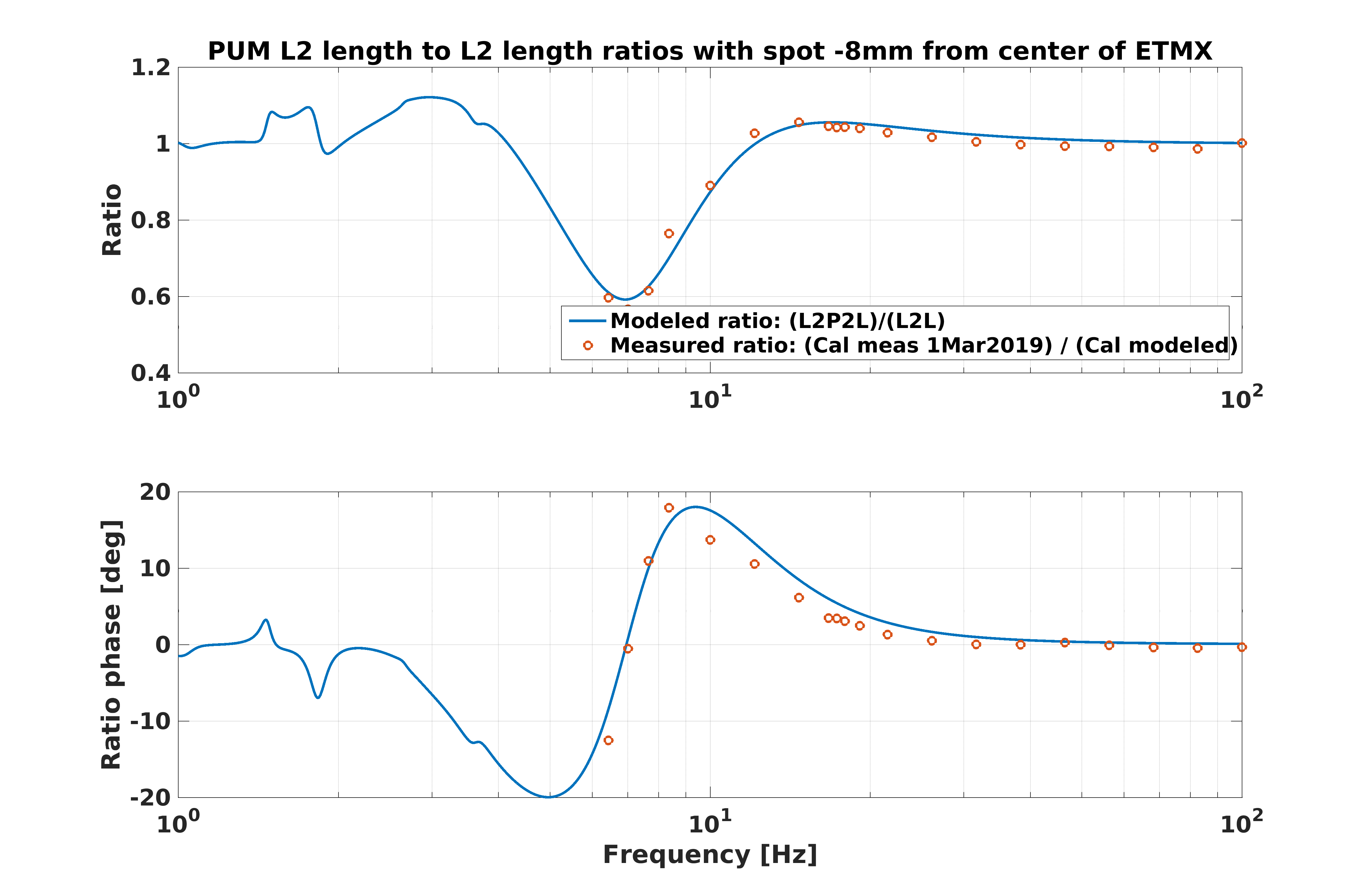
The first attachment shows the modeled ratio plotted with the measured ratio for a spot position of -14mm, which is where the spot was at the time of the measured data (we're at -18mm on ETMX now, but this is an older measurement). You can see that the modeled ratio shows a larger discrepancy from unity than the measured ratio. If I guess-and-check a few spot positions, I find that a spot position of -8mm makes the data match the modeled ratio more closely, but recall that the model is missing effects such as yaw couplings. The -8mm spot position model is shown in attachment 2. The final attachment is a zoom out of the -8mm model, and you can see that it makes a fairly significant difference at around 4.2 Hz, where we have been having troubles with our PUM crossover. We should use this more full PUM length actuation to Test mass motion model for future DARM modelling work.