Last week, we identified our 10.430 kHz mode as being on ETMY (alog 50192). It is potentially the 'flower' higher order butterfly mode, but we have not yet fully distinguished between this and a drumhead mode (alog 50209 and comments).
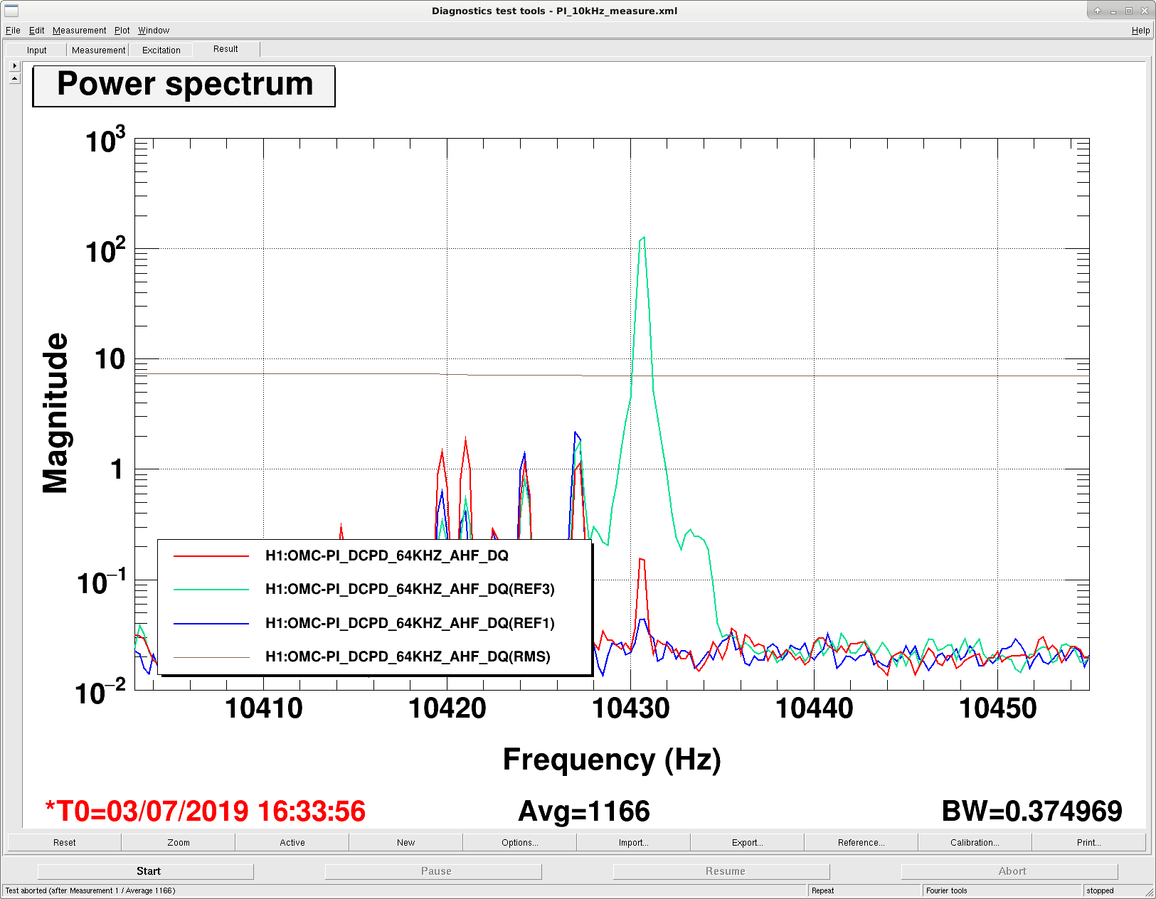
Yesterday I attempted, and today I think I actually got data for measuring the Q of this mode, using the method in alog 50209 and comments. I think the reason that Georgia had trouble ringing up the 10.430 kHz mode is that the bandpass for this damping loop (that we use for anti-damping to ring it up) was centered around the 10.427 kHz mode and wasn't really seeing the 10.430 kHz mode. I ended up needing -60 degrees of phase and positive gain in the damping filter when the bias voltage on ETMY was negative (positive offset in H1:SUS-ETMY_L3_LOCK_BIAS_OFFSET, but the gain of that filter bank is -1). With the gain of the PI Mode24 damping filter high enough to get the ESD to be railing (H1:SUS-ETMY_PI_ESD_DRIVER_OUT_RIGHTMON more than 150k counts), I was able to get the 10.430 kHz mode to be 3.5 orders of magnitude higher than its baseline value at 2W.
In the attached figure, the blue trace is about the OMC DC PD fast channel's baseline value when we're locked at 2W. The teal trace is as high as I rung the mode up to, and the red is where the mode was when we started the power up sequence on the way to NomLowNoise. So, I didn't let the mode ring all the way down, since we were starting to see similar ASC instabilities as we saw yesterday when we stayed at 2W for a long time. Not sure why we're getting this 0.54 Hz resonance in MICH, DHARD, and INP1 after an hour at 2W, but it is likely that we just don't have the ASC RF PD phases tuned to be happy at 2W or something.
Strange is that the RMS channel that monitors this PI mode doesn't seem to respond sensibly to the ring up and ring down of this PI mode. The RMS is just looking at the bandpass that is part of the damping loop that I'm using to ring up the mode, so it should be totally obvious and clear and we should see the RMS change. So, I don't yet have an answer for the Q value - I'll have to do some math and comment later today.