After Wednesdays commissioning discussion, I added mode-mismatching to the cavity model used in 50589 to enable internal SRC<-> ARM mode mismatch in its 2-mode rotation-matrix approach. This is to study how relevant the internal mode-matching is to squeezing and frequency dependent degradations to shotnoise. Internal mode matching is a bit more tricky, as the "best" operating point for the cavity model becomes non-trivial. Finesse and other transverse-mode capable simulators have tools to tackle this problem, but I'm not aware if any lock-point optimizers which handle squeezing in a simple manner. Because of frequency-dependent degradation, optimizing lock points is not uniquely defined and in principle, optimizing SQZ'ed spectra for BNS range or "science case" is the most general solution. Unfortuantely, this kind of optimization is very opaque for complex simulations.
I derived a few metrics to make finding lock-points more tractable for this two-cavity SRC+IFO simulation. Past studies have focused on the SRCL tuning - to optimize the sqz angle rotation, and measuring SQZ Loss and phase noise. There is one more important degradation that has not been studied in interferometer measurements or simulations. This is the loss imbalance in upper/lower sideband transfer of the squeeze field. This effect is known from how it can degrades the filter cavity operation, and not previously expected in the interferometer operating in its nominal SRC/ARM tuning. In T1900446 I derive the metrics, and show that the parameter "d", related to unbalanced loss in the arms, will cause a degradation that behaves identically to phase noise, except in a frequency-dependent manner. It also shows concise formula to help set the operating point of the squeezer in a simulation. The similarity to phase noise means that it is an irriducible coupling of anti-squeezing into the observation quadtrature (phase).
The reason that loss imbalance couples anti-squeezing is that the squeezing relies on a magnification of quantum noise from parametric gain, with a corresponding correlation in the upper and lower sidebands that allows them to strongly cancel in the readout (despite the magnification). The squeezing angle modifies the correlation from cancelling to adding, rotating from squeezing to anti-squeezing. Phase noise is a background modulation of the rotation between the two. Loss imbalance removes the correlation, but not the magnification to the noise, which also causes irriducible anti-squeezing. Loss imbalance in the SRC reflected sidebands could potentially account for the apparent phase-noise excess observed at both sites.
The question is whether after fixing the sqz-angle detuning (SRCL offset), there can be imbalance in the loss on sidebands of the SRC reflection, even with the sideband phasing well-balanced. It appears that this is possible. It is a weak contribution with loss and mode-mismatch within the SRC. For mode-mismatch outside of the SQZ to IFO, the contribution is much stronger, altough in this model does not saturate the observed excess phase noise.
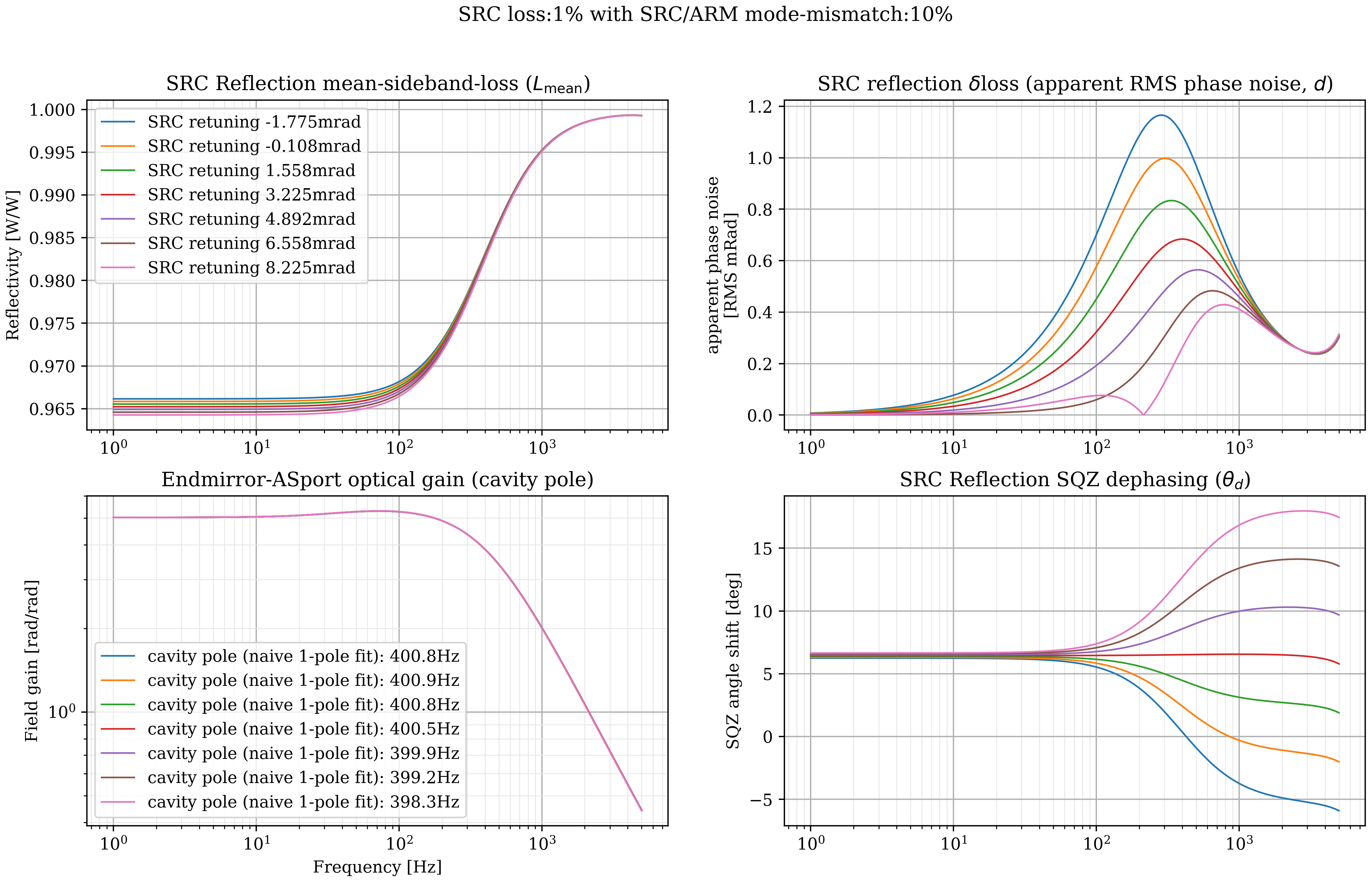
cavity_pole_SRCtuningSRCmm.png shows a set of transfer-functions of the 00-mode reflecting from the SRC. The mode-matching of the SQZ to the IFO is perfect, but the SRC has 1% loss and 5% mode-mismatch to the arms. The code in coupled_cavity.py shows the full equations for the cavity reflection in the function coupled_cavity(...). There the 2-mode cavity model is applied to both upper and lower sidebands, giving
r_src(+F) and r_src(-F)
which is initially nF x 2 x 2 matrix for the HG00 and HG02 modes modeled. Here, only the HG00->HG00 coupling is used, since the mode-matching to the OMC is assumed perfect, so r_src is a scalar. This r_src is the h(f) in T1900446.
arg(r_src(+F) * r_src(-f))/2 is the squeezing angle upon reflection from the cavity. This is the lower-right plot. The SRC tune-phase (Shiela's SRCL scans 50591) is adjusted and optimized to flatten the squeezing angle, showing that there is a tuning which has no residual frequency depenence to the squeezing angle. This is observed as having the optimal noise independently at each frequency.
abs(r_src(+F) * r_src(-f)) is the upper-left plot, the (geometric) mean sideband Reflectivity. This is related to how much unsqueezed vacuum creeps in. min/max(abs(r_src(+F))**2, abs(r_src(-f))**2) sets bounds on this number. The "c" and "L_mean" metrics are similar and nearly equal to this, but, when the losses are substantially different and these loss metrics show some discrepancy, the noise will not be dominated by the vacuum, but rather the loss-imbalance, so the geometric mean is a sufficient heuristic.
When the upper/lower sideband reflectivity losses are different, the imbalance is expressed by
d = abs(abs(r_src(+F)) - abs(r_src(-f)))
This is shown in the upper right. This is a rather conceptually-opaque expression, but is derived to act just like RMS phase noise.
The lower-left of the plot is the cavity pole. At this level of mode-mismatch the DARM sensitivity has a considerable pole-splitting. The fits are using only a naive single-pole, but it is reported as a figure-of-merit to relate to the current/past cavity poles. It is surprising that an operating point exists with a flattened SQZ angle despite the pole-splitting, which is from a single optical pole aliasing to different frequencies in the upper-lower -> quadrature sideband projection. Such aliasing causes frequency effects on the angles that would not be expected to cancel so exactly without also cancelling the pole-splitting. It must be that the DARM-xfer and SQZ SRCrefl xfer sample sufficiently different things that this is possible. These transfer functions might suggest that SRCL tuning should not affect calibration, but RPN is not included and the optical-spring effects are missing.
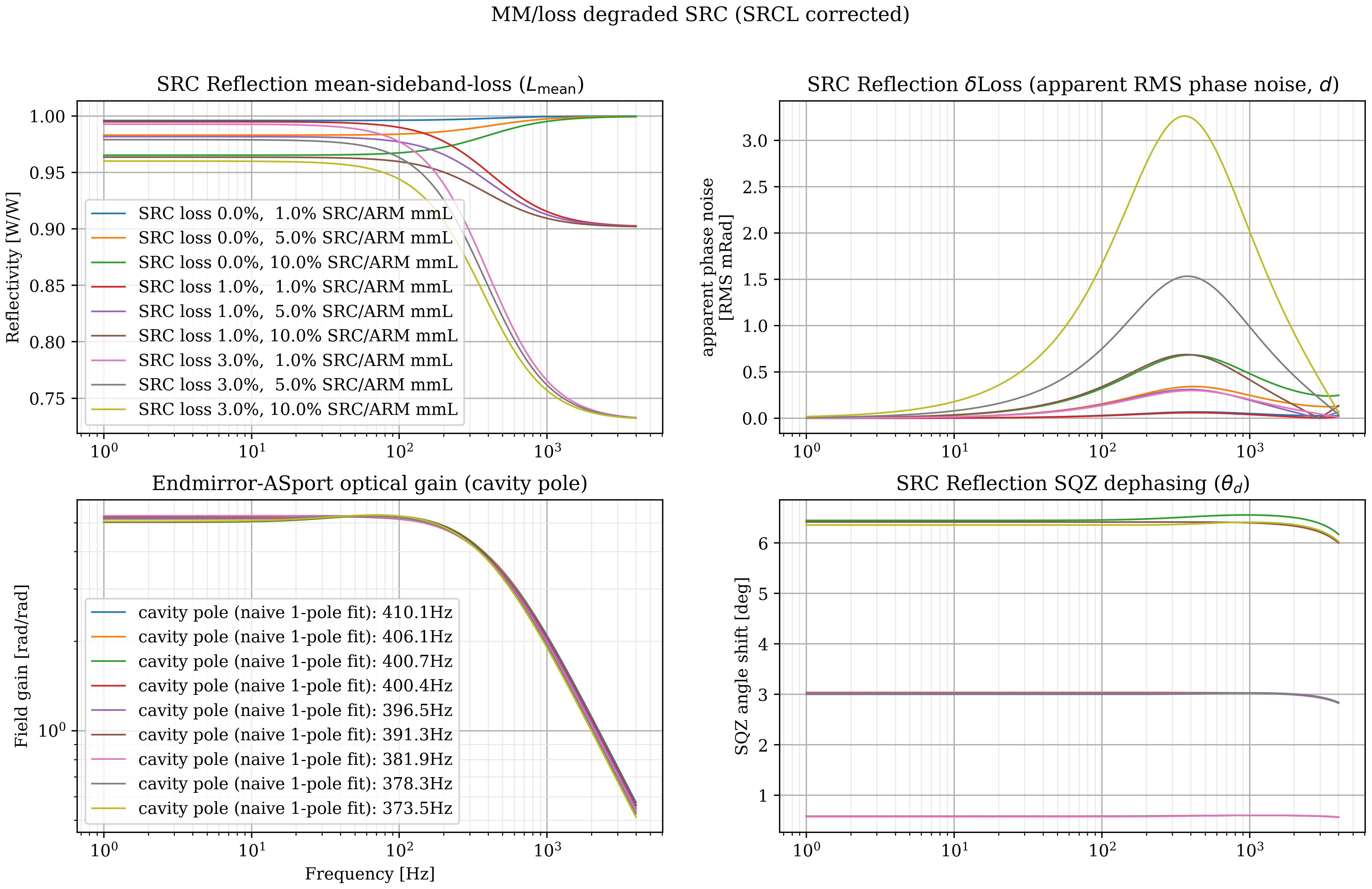
cavity_pole_SRCtunedSRCmm.png Performs the same analysis, where the SQZ-angle shift is always optimized for flatness, and the SRC mode-mismatch loss and dissipative losses are varied. These show that further degradation strongly affects loss at high-frequencies (from SRC loss), but these do not affect loss-imbalance significantly.
Now, introducing mode-mismatch between the SQZ and IFO gives a different story.
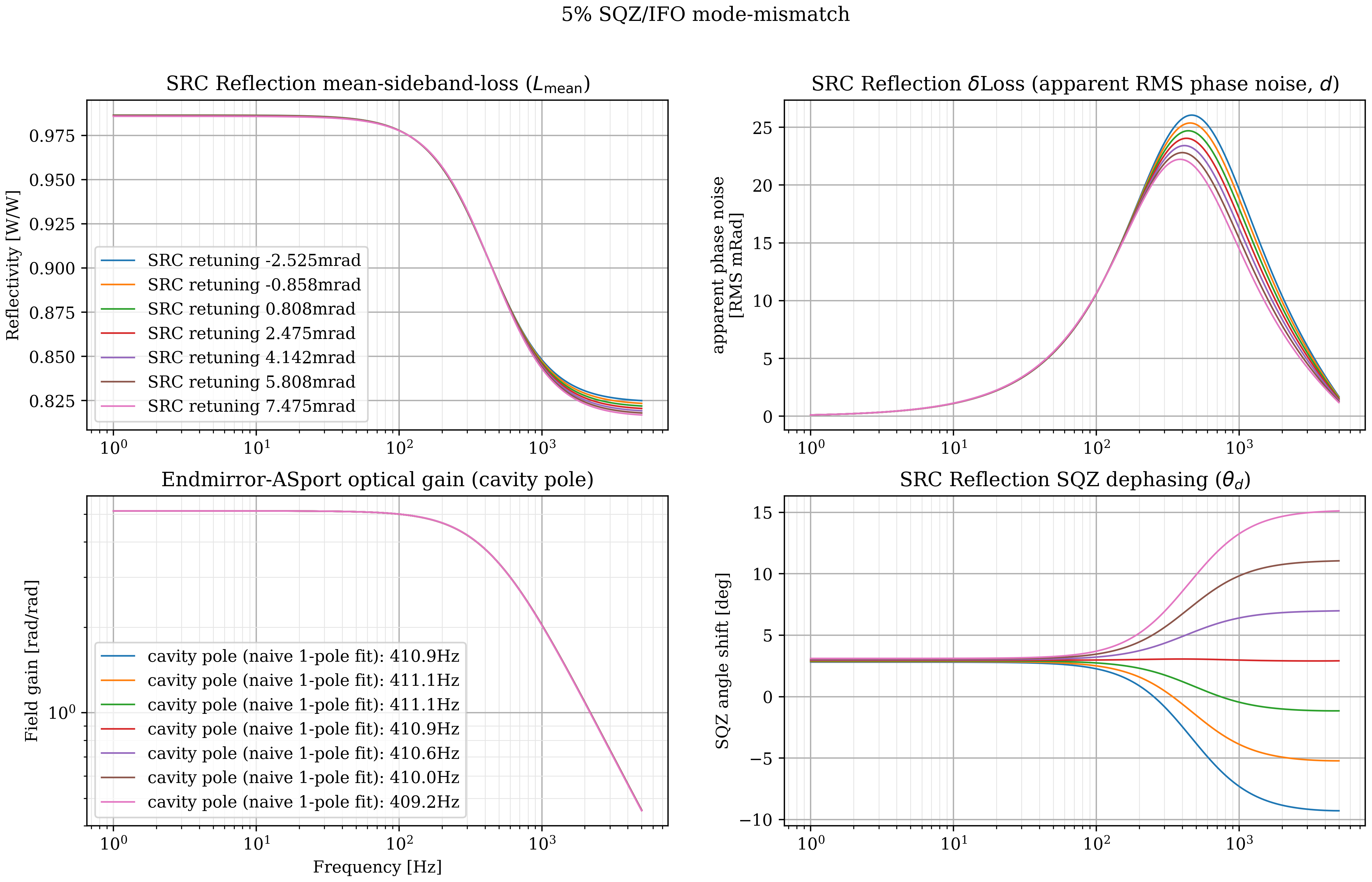
cavity_pole_SRCtuningIFOmm.png shows the metrics with 5% SRC/ARM internal mismatch loss, as well as 5% SQZ/IFO. The curves show different SRCL tunings. At high-frequencies this large IFO mismatch causes a large effective loss, and at intermediate frequencies, it causes substantial phase noise as well (although not as much as we are looking for).
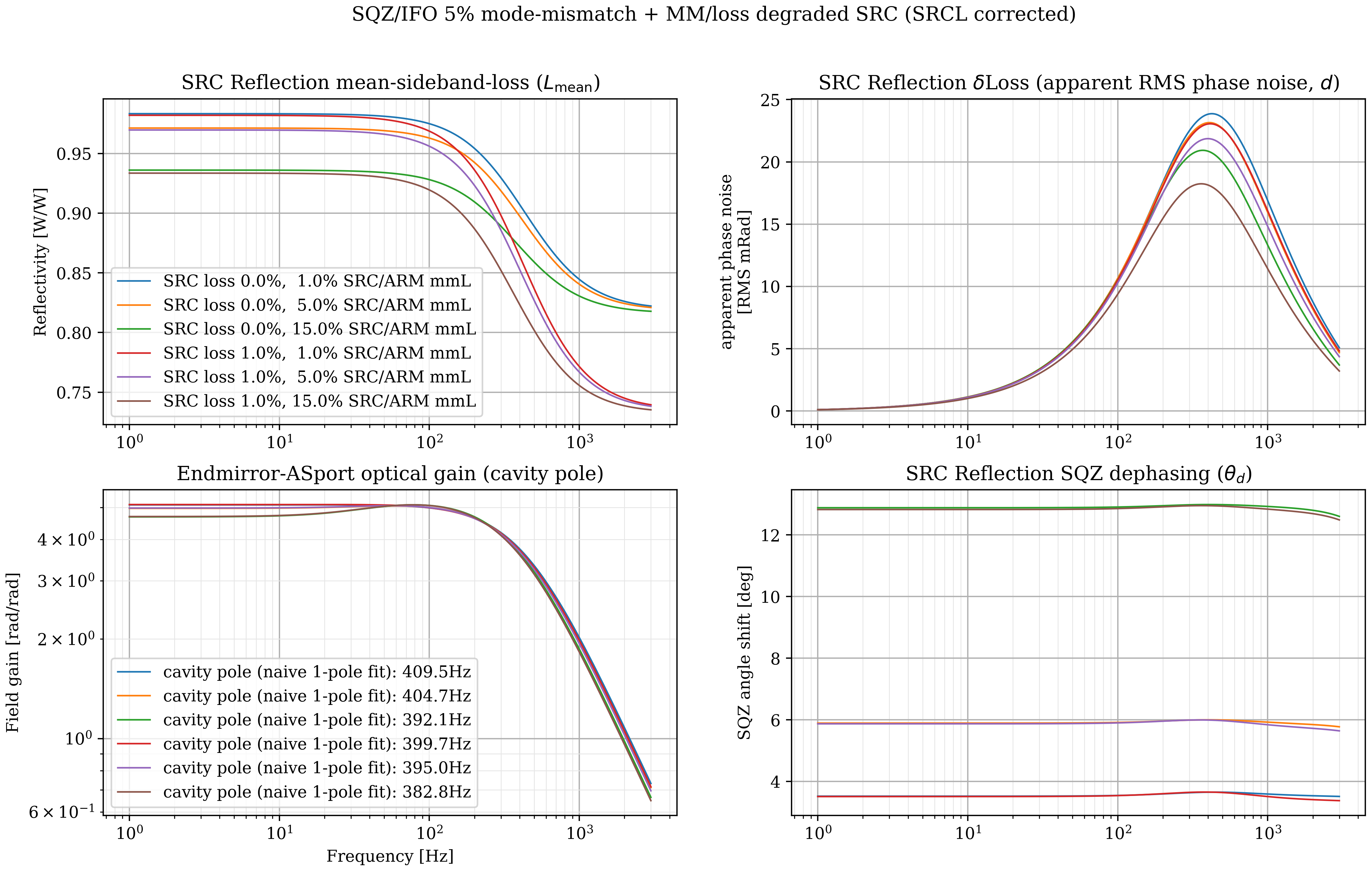
cavity_pole_SRCtunedIFOmm.png Shows 5% SQZ/IFO mode-mismatch, with tuned SRCL, but varying the SRC loss and SRC/ARM mismatch.
From some studies not shown, the differential loss (apparent phase noise) is affected by the SRC Gouy phase (I am using .345rad, 19.8 deg, or .11/FSR single-pass for the HG02). When the Gouy is decreased, the loss-imbalance grows. This suggests that a model of HG01 alignment noise, using less Gouy from the lesser mode, will show larger degradation.
I matched these Gouy phases by using this model to simulate Jon Richardson's measurements in LLO39779 Interestingly, those measurments show a 30db dip in SRC reflectivity! This can indeed happen when mode-mismatch is bad, and similar measurements (at lower frequencies) may be useful in the future to characterize SQZ degradations.
Although this model does not saturate the observed losses and phase noise, It suggests that further studies of the controls noise may show substantial contributions from residual motion RMS. A more complete simulation will also be insightful and hopefully these metrics will be useful for even more complicated models. Loss-imbalance might be a canidate for the squeezing "phase noise" identified in advanced detectors.


Errata: The DARM transfer function resonance (lower left) that is visible is not right. The code has two matrix-multiplies switched, but only on the endmirror-to-OMC transmission that indicates the DARM transfer function. The other three squeezer plots and code should be OK. Fixing the matrices gives no resnant feature, but does predict DARM pole changing.