J. Oberling, T. Shaffer
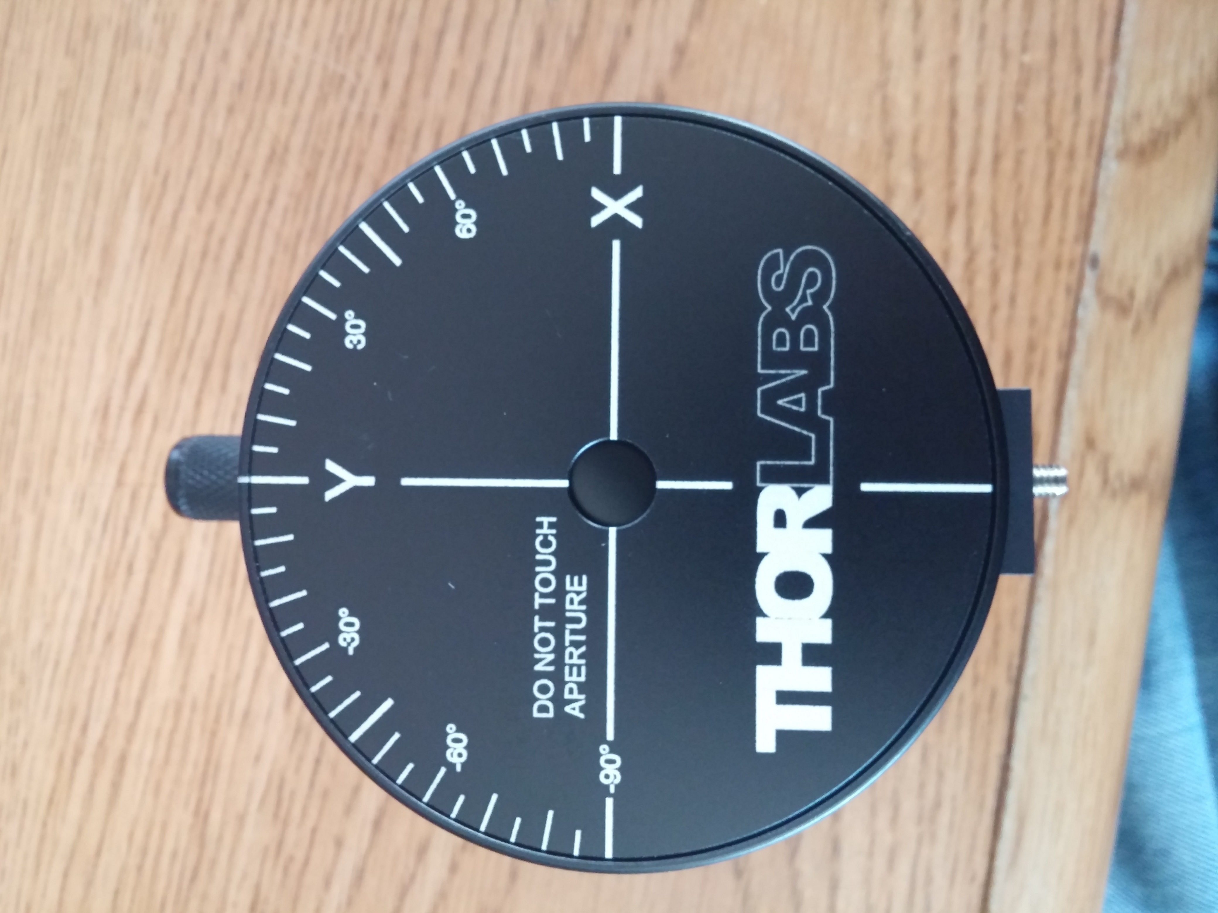
Following on from Round 1 last week, TJ and I went out to ISCTEY this morning with a ThorLabs BP209-VIS scanning slit beam profiler to see if we could identify where the ALSy green beam was becoming elliptical (as first identified by Georgia, Laurence, and Dripta here). Because of how scanning slit profilers work it is entirely possible to miss ellipticity that is rotated 45° w.r.t. the profiler's sensor. Luckily the BP209 allows the user to rotate the sensor plane to account for this (from +90° to -90°), so we took 2 profiles at each point: 1 with the sensor head at 0° and one at +45°. To see the sign convention for the sensor rotation, I've included a picture of the front face of the BP209 (1st attachment); the entire face rotates, with the small white line (lined up with Y in the picture) being the fiducial for setting the sensor angle. As the ALSy green path is quite crowded, there were only 2 points where we could fit the profiler: after ALS_HWP6 and after ALS_HWP5 (ALS_HWP6 preceeds ALS_HWP5 in the beam path, see the table layout here).
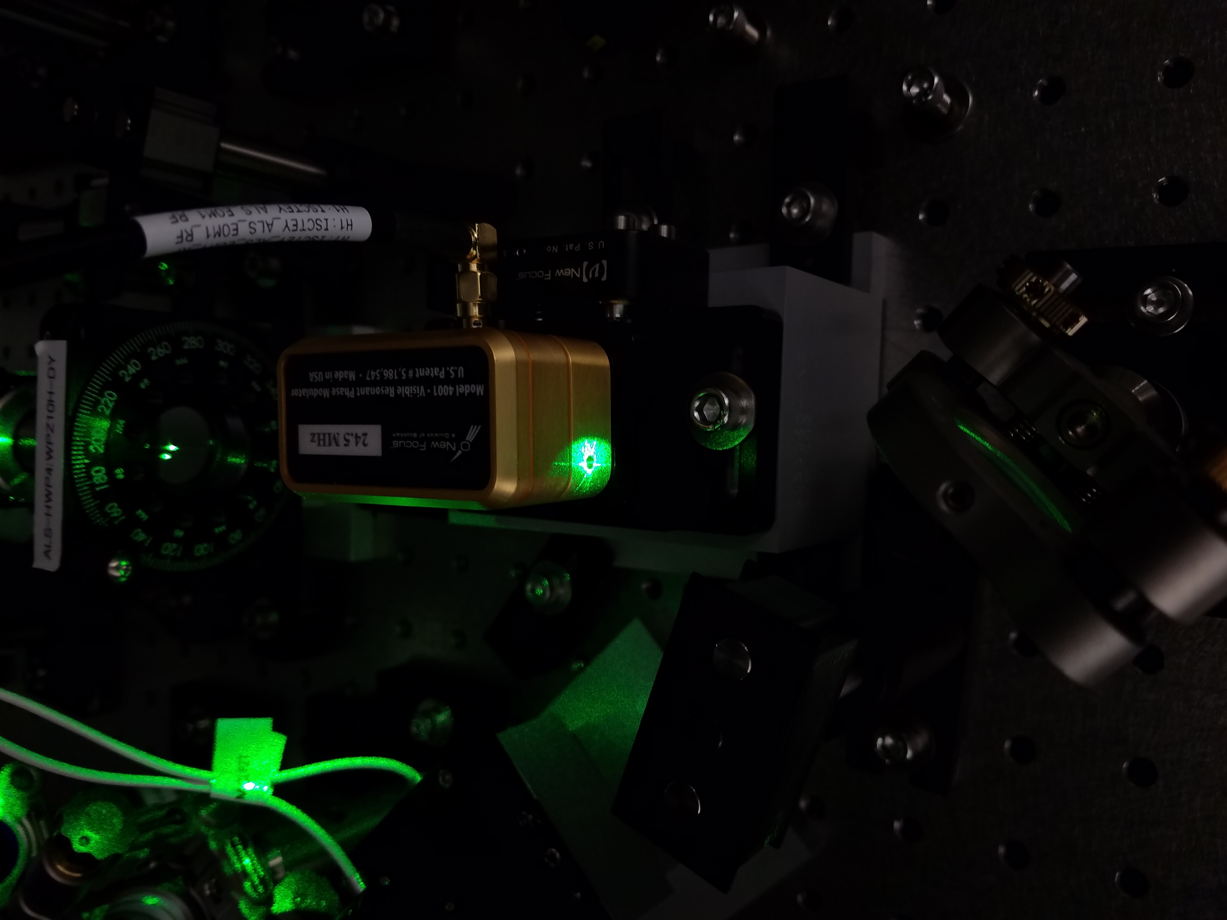
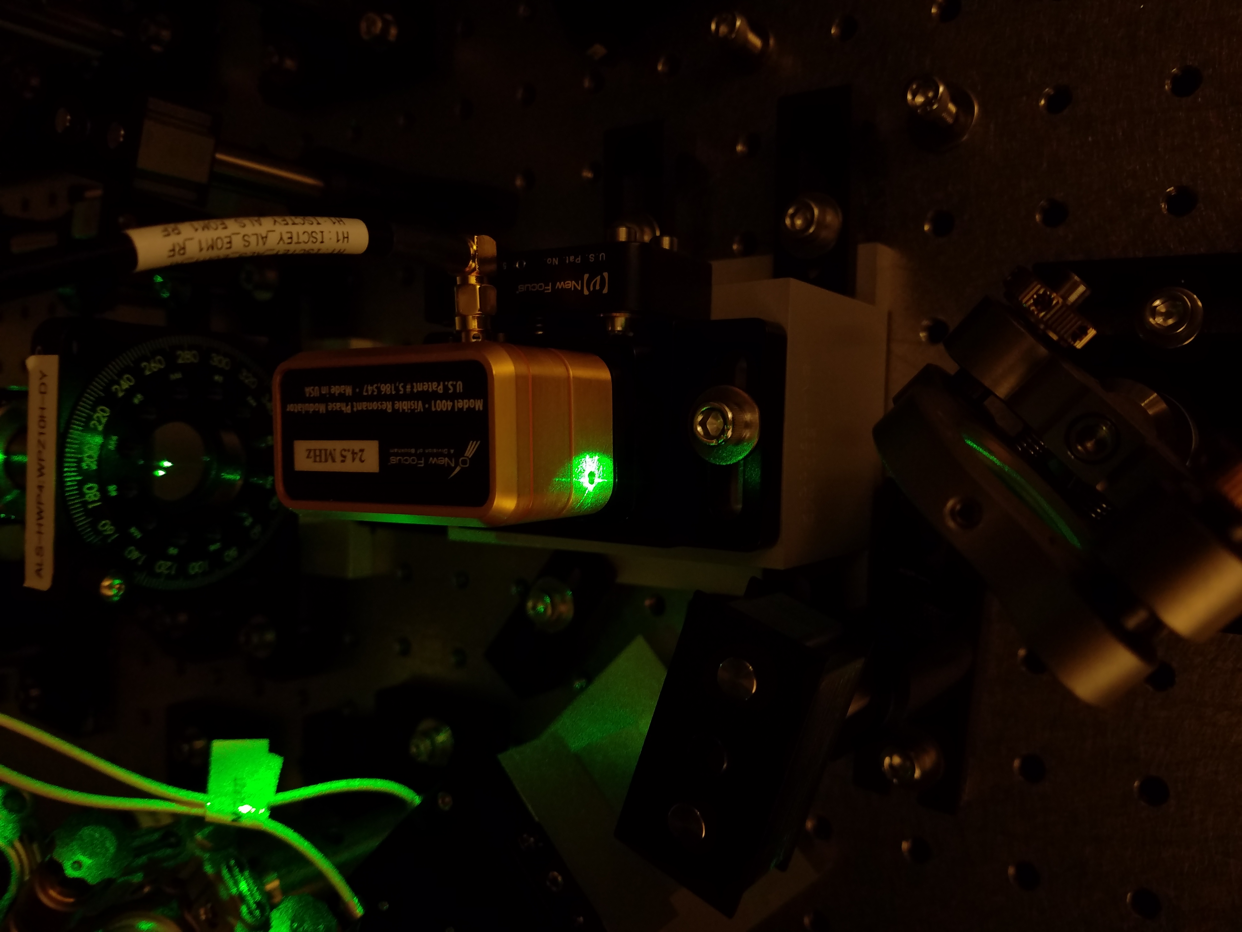
First things first, as reported in Round 1, I suspected the green beam was clipping on the entrance aperture of the EOM, so I tried to get a picture to show this. Unfortunately the green beam completely washes out the EOM entrance aperture, and my phone camera is too old to have saturation controls to clean this up; see the 2nd attachment. Looking at my phone pics, one cannot discern if there's any clipping; best I can say is there's some scatter being picked up by my phone All was not lost, however, as TJ has a newer phone and was able to get much cleaner pictures, which he will attach as a comment to this alog. Looking at TJ's pictures, it appears the beam is in fact clipping on the entrance aperture of the EOM.
Before we took any beam profiles, I first wanted to check the power at the 2 locations we were planning on taking profiles (don't want to damage the profiler); an Ophir PD300-3W-V1 3W head was used in conjunction with an Ophir VEGA for this measurement. The powers measured as follows:
- After ALS_HWP6: 38.9mW
- After ALS_HWP5: 32.0 mW
Max power on the BP209 is ~100mW for a 1mm diameter beam, so we're good to go. We then proceeded to take the profiles at the locations mentioned above; see last 4 attachments. Unfortunately, the beam profiler with the addition of its power/signal USB cable (which sticks directly out of the back of the unit) was too long to get more than one profile at each location, so please keep that in mind when looking at the attached profiles; as I said, this section of the green path is a little crowded (the profiler barely fit between ALS_HWP5 and ALS_L5). Please note, all lenses were left in the beam path (specifically ALS-L4) as removing then reinstalling them can cause an aligment shift. While alignment can be recovered, it is a non-trivial exercise not to be undertaken lightly.
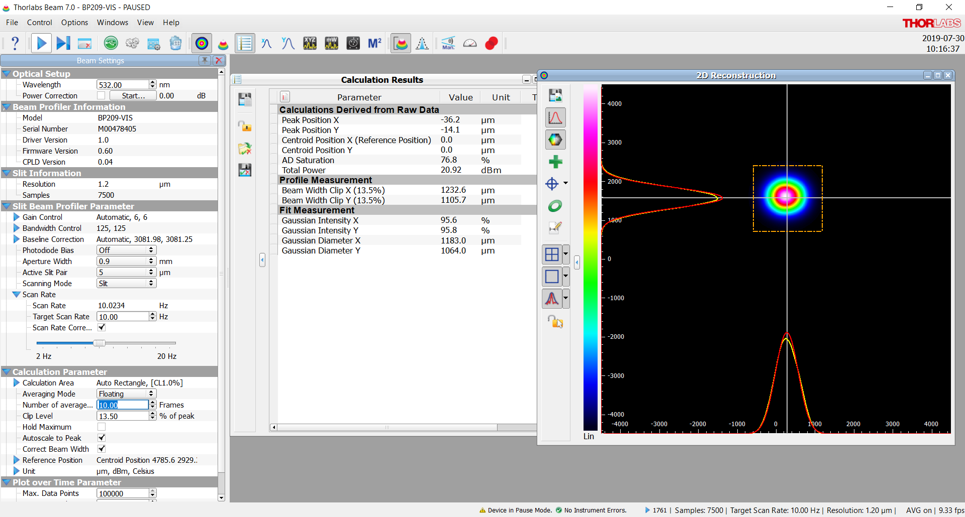
Profile #1: After ALS_HWP6
The beam here, in my opinion, looks OK. Not great, but OK. Slightly elliptical with the horizontal axis being ~11.5% larger than the vertical, but nothing grossly out of order here. Rotating the sensor head by +45° doesn't reveal any gross off-axis ellipticity; in fact, the beam looks more round, indicating that the profiler is missing the slight ellipticity seen when in its normal orientation.
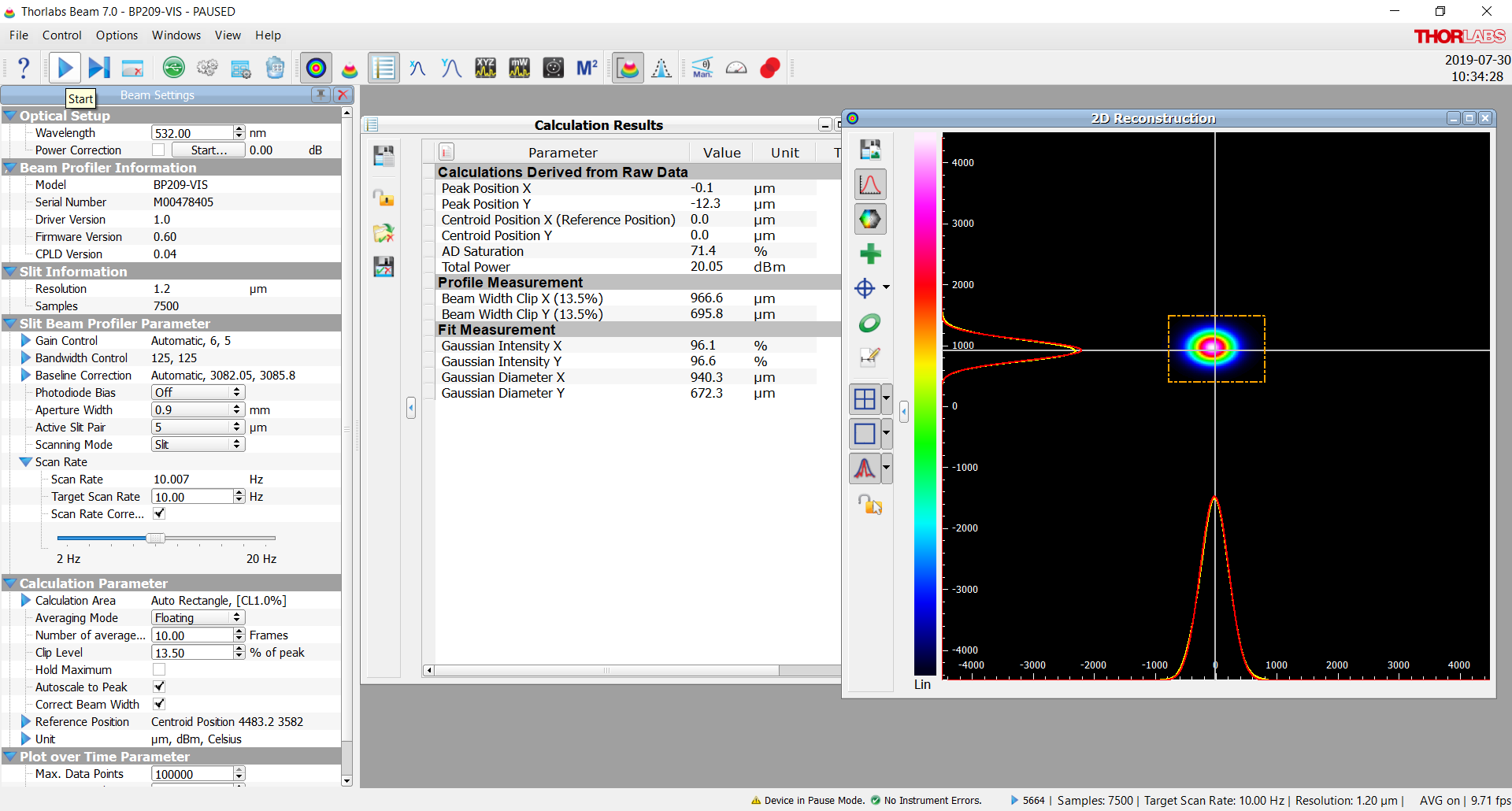
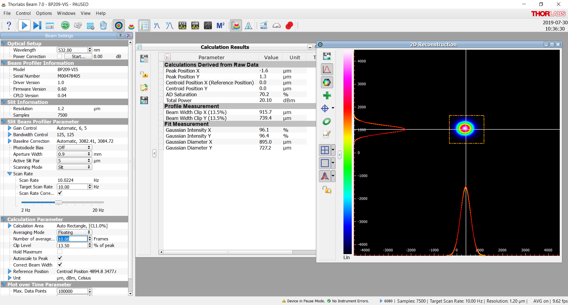
Profile #2: After ALS_HWP5
Here, things get interesting. The beam is obviously elliptical at this point, with the horizontal axis being ~38.9% larger than the vertical. As with the 1st profile, rotating the sensor by +45° does not reveal any gross off-axis ellipticity; also as with the 1st profile, the beam looks more round.
With the above being said, the beam diameters measured are roughly consistent with the mode matching simulation performed when the table was assembled in 2013; see Figure 13 of T1300837. From Figure 13 it is apparent the beam was expected to be elliptical throughout the beam path. This ellipticity is caused by the horizontal and vertical waists being in different locations. The 35W FE in the PSL shows similar behavior, as does the spare SQZ NPRO I recently tested, so this isn't entirely unexpected. While the clipping observed should be corrected (and is most likely contributing to the bad mode matching), based on T1300837 it is less clear to me that the ellipticity measured today is the root cause of the issue.
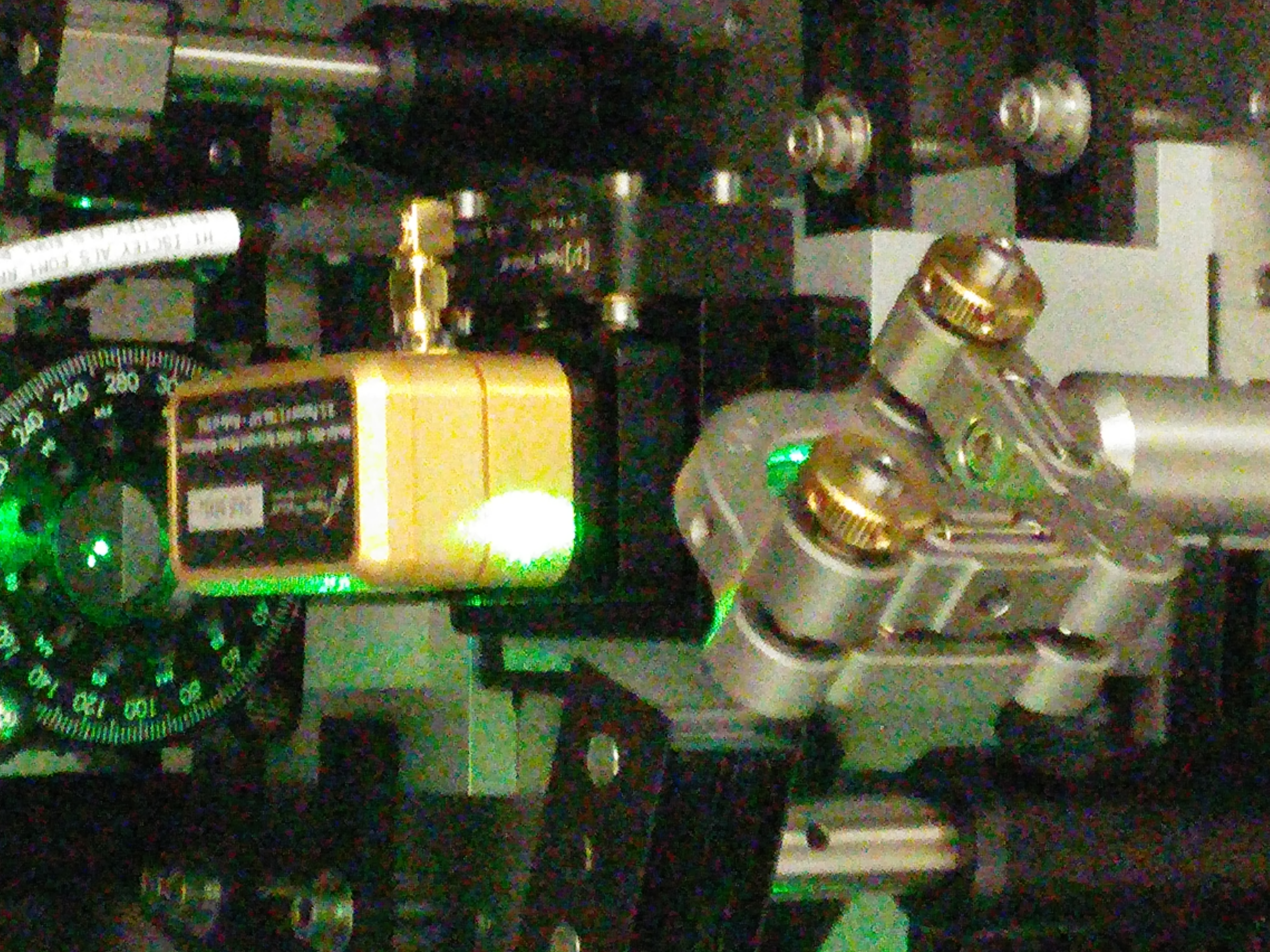

Here are a few pictures of the clipping going into the EOM, but with different camera settings (couldn't tell you what they are at this point).