M. Ball
The end test masses suffer from coupling between angular rotation and linear displacement that can have an impact in DARM calibration (alog 50498). A few suggestions have been made to combat this (alog 49825) which I have modeled a bit: we can split the A2L filters into a scalar spot position term and a frequency-dependent term, and reroute the output of the L2A filters into the A2L filters.
The angle to DARM coupling goes like (for pitch only):
A->D=A2A(A2a*m+A2l)+A2L(L2l+L2a*m)
Where A2A is the digital pitch to pitch filter, A2a is the mechanical pitch to pitch transfer function, A2l is the mechanical pitch to length transfer function, A2L is the digital pitch to length filter, L2l is the mechanical length to length transfer function, L2a is the mechanical length to pitch transfer function, and m is the spot miscentering on the test mass. To remove this coupling, we can choose a digital, frequency-dependent A2L filter that makes this go to zero:
A2L=-A2A(A2a*m+A2l)/(L2l+L2a*m)
However, the dependence on m is nontrivial here. If we could remove the m-dependent term in the denominator without any significant impact, we could separate this into two separate filters:
A2L = -(A2A*L2l/A2a)*m-A2A*A2l/L2l
I have plotted this A2L filter with and without the m-dependent term in the denominator using transfer functions from the QUAD model and A2A=1 (figure 1). These filters are nearly identical for m=-15.7mm, suggesting that this separated filter can hold even for relatively large beam offsets. Separating this filter in this way should be an acceptable method for a frequency-dependent filter.
The length to DARM coupling goes like:
L->D = L2A(A2a*m+A2l)+L2L(L2l+L2a*m)
When routing the L2A filter output into the A2l and A2p mechanical transfer functions. Similar to above, terms like L2L are digital filters and terms like L2l are mechanical transfer functions. We can also reroute this output into the A2L digital filter, which makes the coupling go like:
L->D = L2A(A2A*(A2l+m*A2a)+A2L(L2l+m*L2a))+L2L(L2l+m*L2a)
Additionally, the length to angle coupling theoretically goes like:
L->A = L2A*A2a+L2L*L2a
Ideally, we can choose an “ideal” L2A filter such that this is zero and the angular loops are less impacted by the length drive:
L2A = -L2L*L2a/A2a
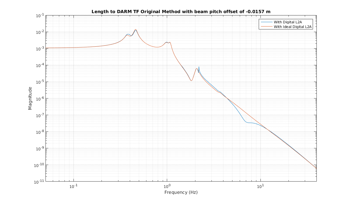
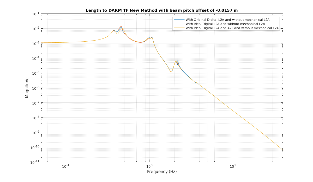
Rerouting the length to angle filter output through the angle to length filter in this loop has a minimal impact on the L2DARM coupling. I have attached plots of the coupling transfer function for routing L2P into A2a and A2l (the “original” method) and routing L2A into A2L (the “new” method). Figure 2 shows L2DARM through the original method with the current L2A filter (labeled "digital") and with the “ideal” L2A filter (labeled "ideal digital") discussed earlier. The dip in the original coupling around 7hz was responsible for calibration problems earlier in the run (alog 48738). Figure 3 shows L2DARM through the new route with the m*L2a term removed (since this term was small compared to the L2l term) with the original L2A filter, the “ideal” L2A filter and a scalar A2L filter, and both the “ideal” L2A and A2L filters discussed so far. The important note here is that in the original route, the change in the L2A filter has a noticable impact whereas with the new route, the change in the L2A filter has a minimal impact.
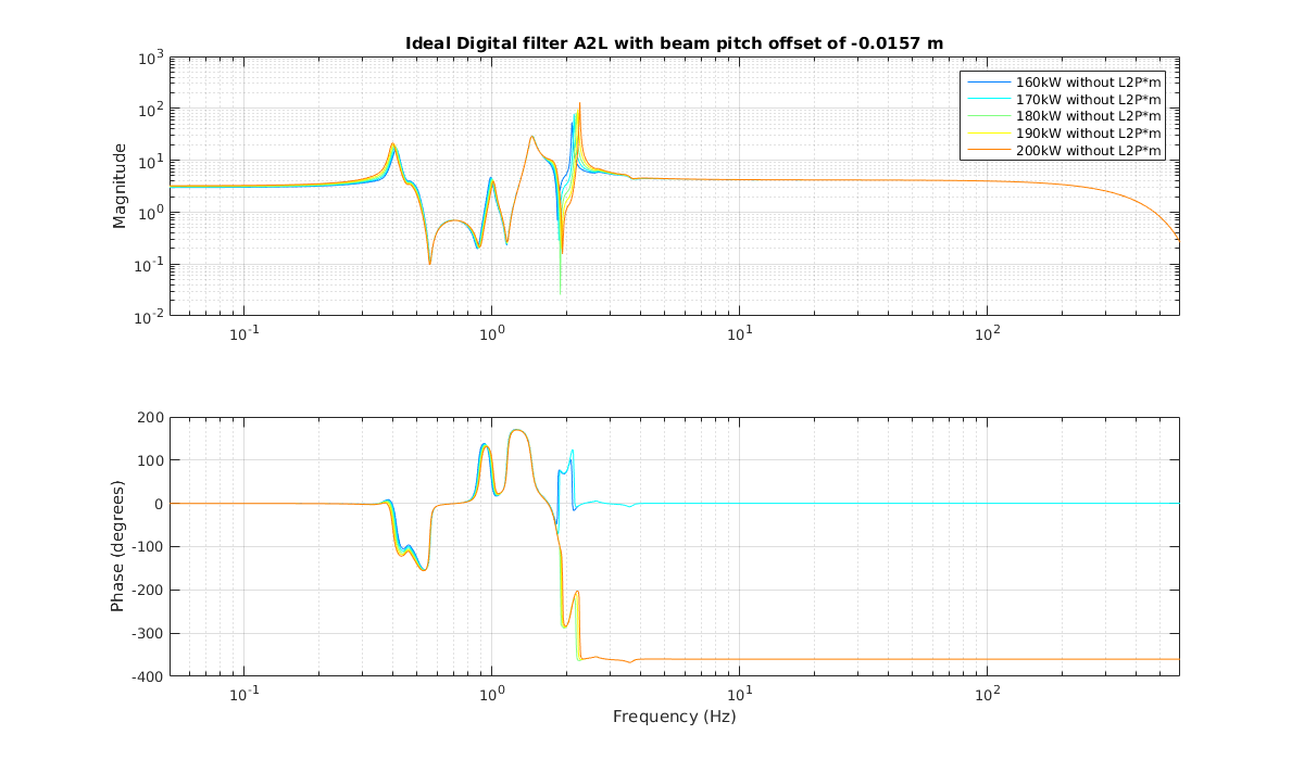
This was all done including the effects of radiation pressure using an arm cavity power of 180kW. There are plans to vary this, so I have also looked at how the “ideal” A2L filter varies with different cavity powers. Figure 4 shows the “ideal” A2L filter at arm powers ranging from 160kW to 200kW. Notice that this frequency-dependent filter is very constant in the GW band, suggesting that a scalar filter may be sufficient.