[Paul, Cheyl, Giacomo]
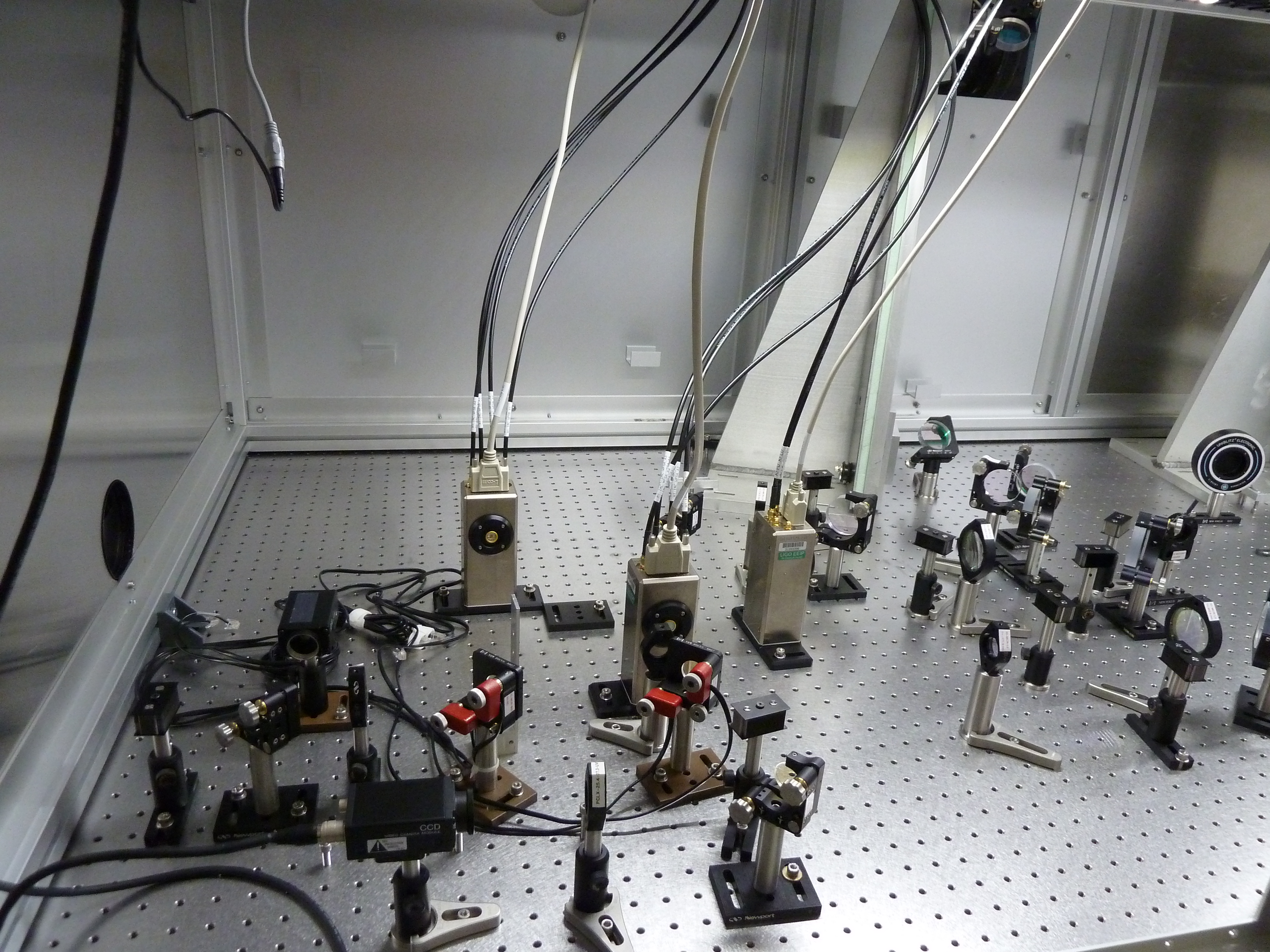
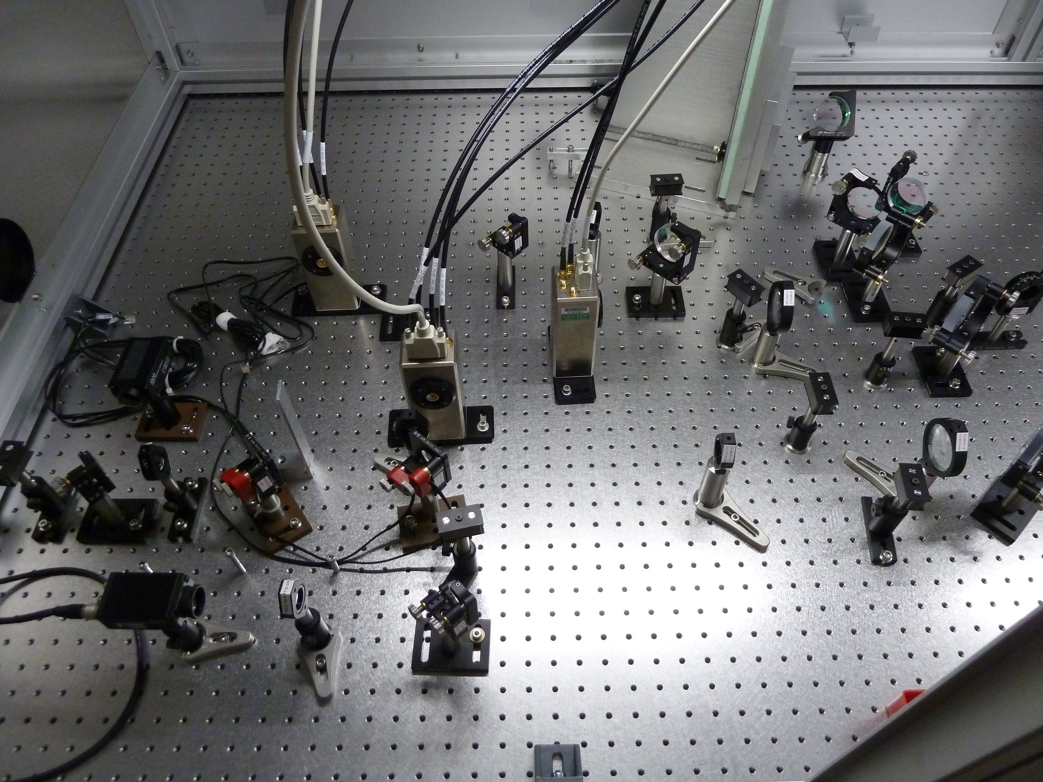
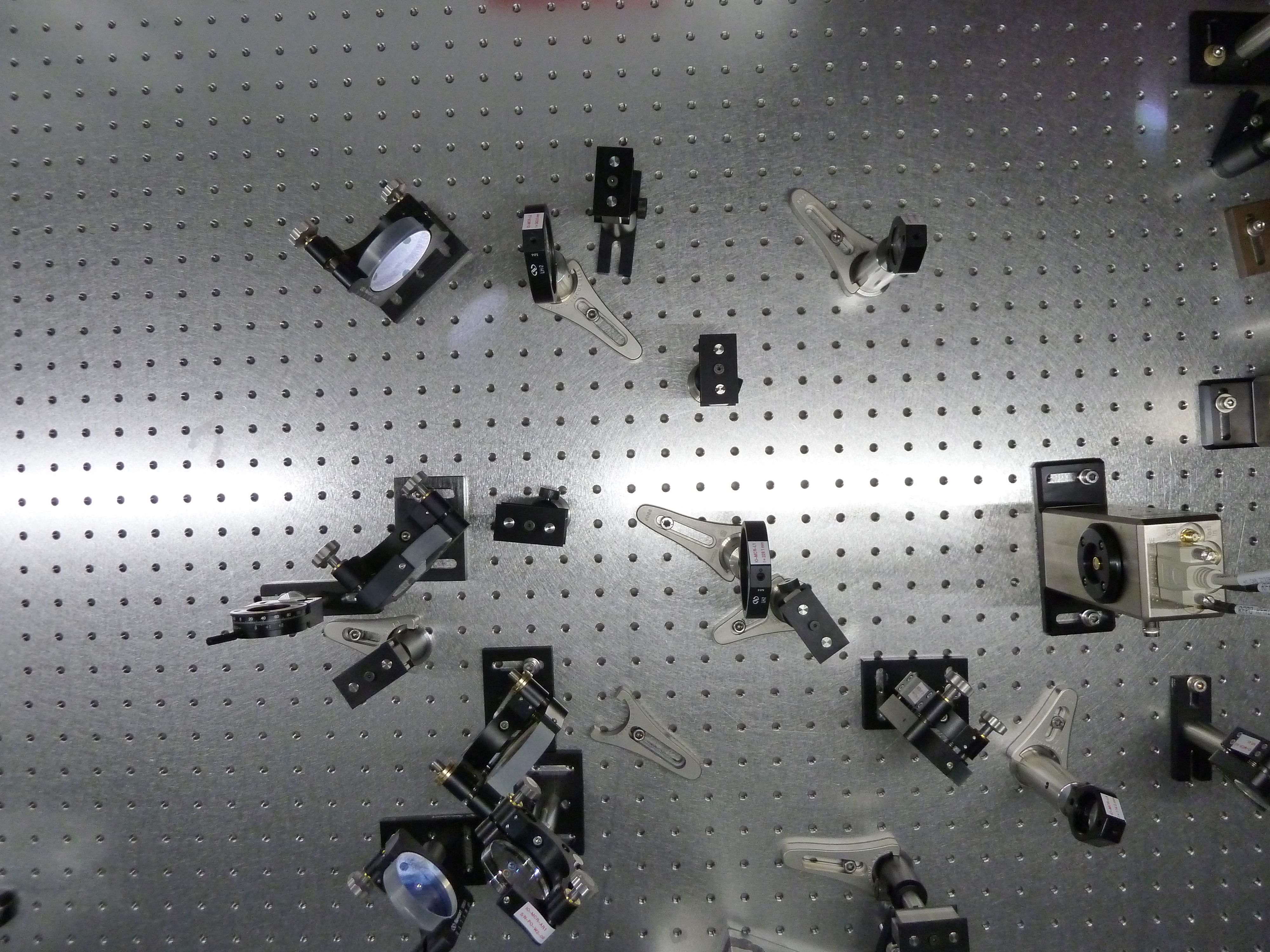
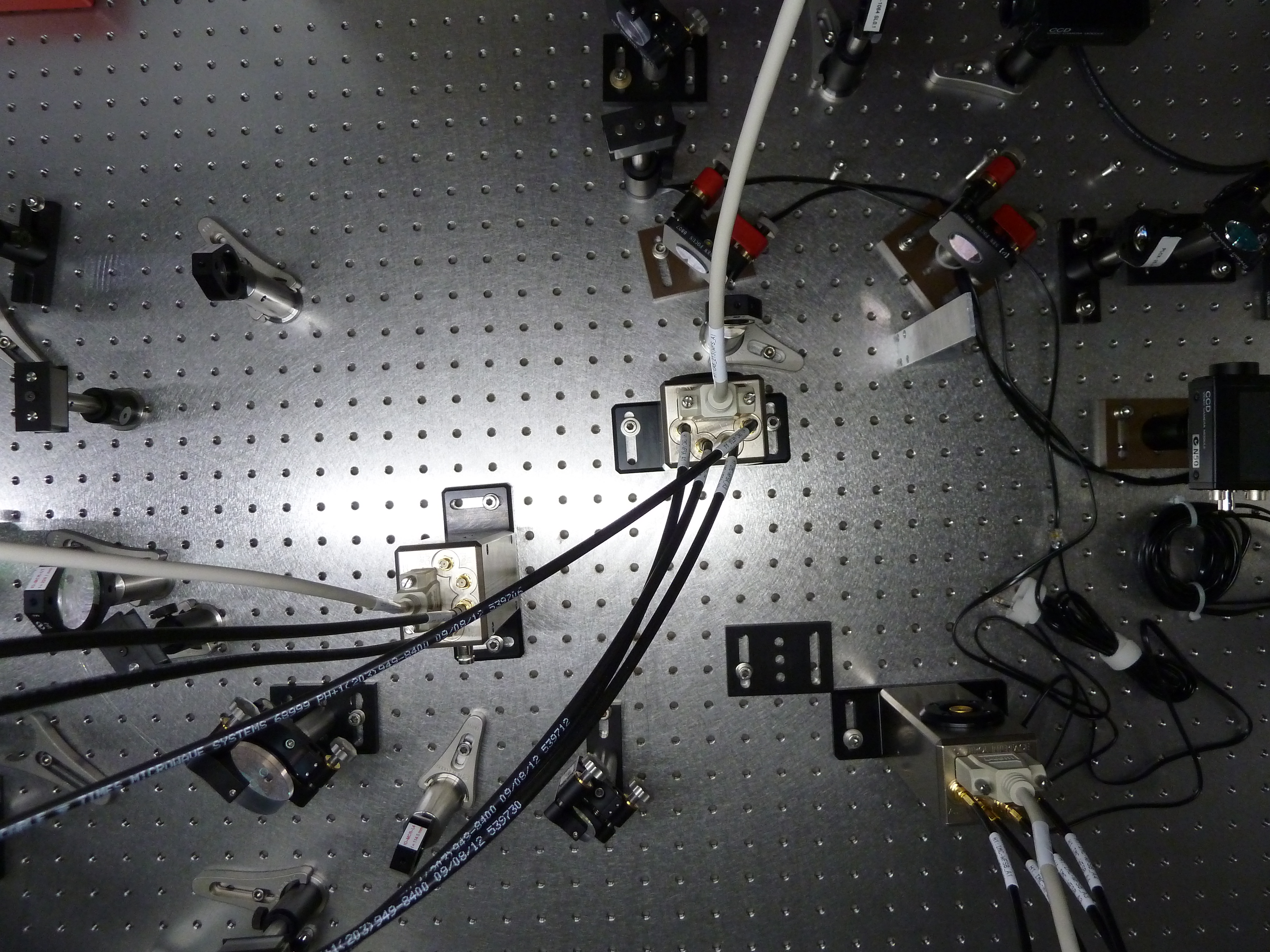
Between Monday and Tuesday we worked at the IOT1 (also very confusingly known as IOT2L = IOT HAM2 Left). We rearranged the IMC refl beam path according to the layout D0902284 (it had previously been layed down temporarily to get an error signal for the IMC locking asap) with the following exceptions and notes:
- the high power beam dump is not there, so we are going on a normal razor-blades beam dump (we will not be using high power though). Also, the other components on that path are not there/in place.
- as per Chris suggestion, we placed that HWP in front of IO_MCR_BS1 instead of in its original location. However, we noticed that it reduced the power at the RFPD by about 50% (independetly from its orientation), so we decided to remove it untill we are confident with IMC locking.
- the shutter is not there
- the GiGe camera is not yet available, so we put an analog camera in its place
- some adjustment has been done to the WFS path, to accomodate for the focal lenses of IO_MCR_L2 and _L3 that are slightly different than the design values. See the following for details.
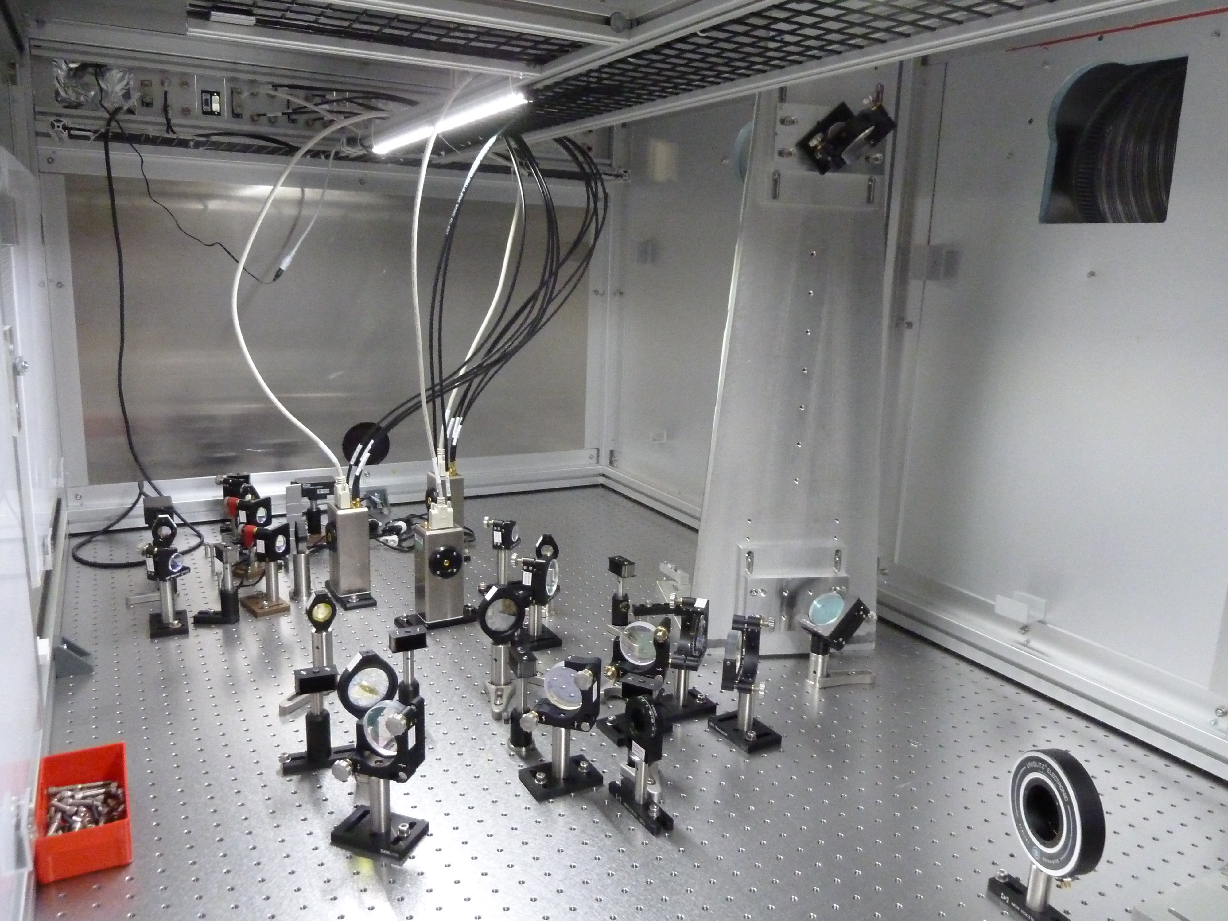
A few pictures attached.
For the WFS path, we placed IO_MCR_L2 in its nominal position, and performed a beamscan using the Ophir Nanoscan. Beamscan1.pdf shows the fit to the horizontal and vertical beam sizes (w0 is ~50 um for both horizontal and vertical)
Also, we measured the beam at a fixed position for different rotations of the nanoscan head around the beam axis, to look for systematics in the observed ellipticity, but we didn't find a relevant effect.
After putting IO_MCR_L3 in a position (it turned out to be about 2" further downstream wrt nominal) that would give about the same waist size quoted on the layout (300 um) we repeated the beam scan, shown in Beamscan2.pdf (w0 is ~275 um for horizontal and ~250 um for vertical).
We then placed the two 45 deg mirrors, put the beamscan downstream and identified the positions (in front and after the waist) in which the beamsize was sqrt(2)*waist (this corresponds to +-Zr from the beam waist, or +-45 deg Gouy phase). As these positions are different wrt the horizontal or vertical beam profiles, we placed each WFS at an intermediate one.
Note that, because the optic mounts have slotted bases, we used temporary clamps to place the 45 deg mirrors in the ideal position (beam centered on the mirror and reflecting at 90 deg). However, later on it was decided to slightly move the mirrors so that they could be screwed to the closest usable hole on the table, thus modifying the pathlength to the two WFS (wrt the waist) by a few mm each. The position of the WFS was not corrected, so for now it can be sxpected to be off by that much (the error is anyhow comparable to the difference between the ideal position for the horizontal or vertical beam profile).
It's also worth mentioning that after a few hours that the WFS were connected to the electronics, we noticed that the metallic enclosure of WFS_A (and only that) was unusually hot to the touch(about 40 C?). We disconnected it and run a series of electrical tests both Tuesday evening and Wednesday morning, without finding any evidence of malfunction. It has been connected since this morning and the temperature seems equal of that of WFS_B (i.e. slightly warmer than ambient). We'll occasionally re-check the temperature of the WFS during the next days.
Finally, Cheryl routed the IMC transmitted beam down the periscope and into another analog camera.