Prior to the installation of the pick off, the power in the ALS beam was measured to be 1.054 +/- 0.001 W in front of
ALS-M2.  Installed a zero order, half waveplate and polarising beamsplitter cube in the beam path.  Adjusted the
half waveplate to measure 1.040 W in front of ALS-M2.  The powers were measured with an Ophir 30A-BB-18 power
meter (S/N 805795).

    At present there is an HR mirror directing the beam to where the fibre would be.  This optic should be replaced
with an optic that has a higher transmission (5-10% perhaps) to allow for a monitoring photodiode.  I found such an
optic in the Optics Lab (unfortunately only after I exited the PSL Enclosure).

distances:
ALS-M1 to half waveplate: 29"
half waveplate to polarising beamsplitter cube: 3"
beamsplitter cube to mirror: 9"

    There is a lens in the ALS beam, labelled LaserOptik R=75 mm 532 nm + 1064nm.  Located ~20" from ALS-M1.
After Peter K added the pick off to the new fiber path in the PSL ALS path, the alignment of the beam onto ISCT1 didn't change much. The addition of a PBS on the PSL table cleaned up the polarization so that we had to adjust the half wave plate before the SHG, after this we have about 90% as much green light for the COMM beatnote as we had before.
The power on the SHG IR PD (the first one after the beam comes out of HAM1) read 60mW before Peter started his work, and only 10mW immediately after. The beam looked misaligned on that diode, so I realigned it with the steering mirror in the pick off path (not changing the main path alignment). This beam might have been misaligned on this diode even before the PSL changes. There is also a rather large looking ghost beam from the back surface of the beam splitter used for this pick off, I wasn't able to measure the power in it because the beams are large and not separated. After realigning the beam in yaw onto the diode it read 30mW, roughly agreeing with a power meter measurement right before the diode. So we have about half as much light in this path as we had before the PBS was added in the PSL. My best guess of what happened was that the IR diode wasn't aligned before Peter started his work, and that the reflectivity of the pick off beam splitter is polarization dependent so that the change in power in this path was due to the polarization change that came from adding a PBS (transmitting hoizontally polarized light).
Using the same power meter that Peter used in the PSL, we measured 1.014W arriving on ISCT1, and nearly 1W going into the SHG. The green power diode was reading 0.89mW before Peter started his work, and 0.21mW after. We checked the alignment of the beam, although it looks to be a bit off to the right side of the crystal the beam is clearing the crystal, is reasonably centered on all the appertures and hits the COMM BBPD diode. This is why we think that any alignment shift from Peter's work must have been too small to explain how off center we were on the SHG IR diode. We adjusted the half wave plate before the SHG and we now have 0.8mW according to the SHG GR PD, or 90% of the green power we had before. We expect the green power to be proportional to the IR power^2, so we would have expected 97% of the green power after using the before and after numbers Peter logged above.
This should be enough green power. It is possible that we will need to adjust the alignment of this path to get a good beatnote, but we have to wait until we have the X arm back to check that.
After the gate valve opened and X arm locked in green, we saw that the comm beat note was down to almost nothing (-32.5dBm).
I and Sheila went to the floor and touched up the SHG path alignment. No change was made to the ALS-X and Y path.
Tweaking the first mirror downstream of the periscope (ALS-M3 in D1201103-v17_ISCT1_H1.pdf) alone didn't do much good, we also had to touch up the COMM beam splitter (ALS-BS3). We also adjusted the HWP after the SHG to maximize the green power coming to COMM, which didn't do much but did something nevertheless.
After the COMM beat note became -3.5dBm, we noticed that H1:ALS-C_SHG_IR_DC_POWER decreased by a small amount (27mW instead of 29), so we touched up the alignment for that path.
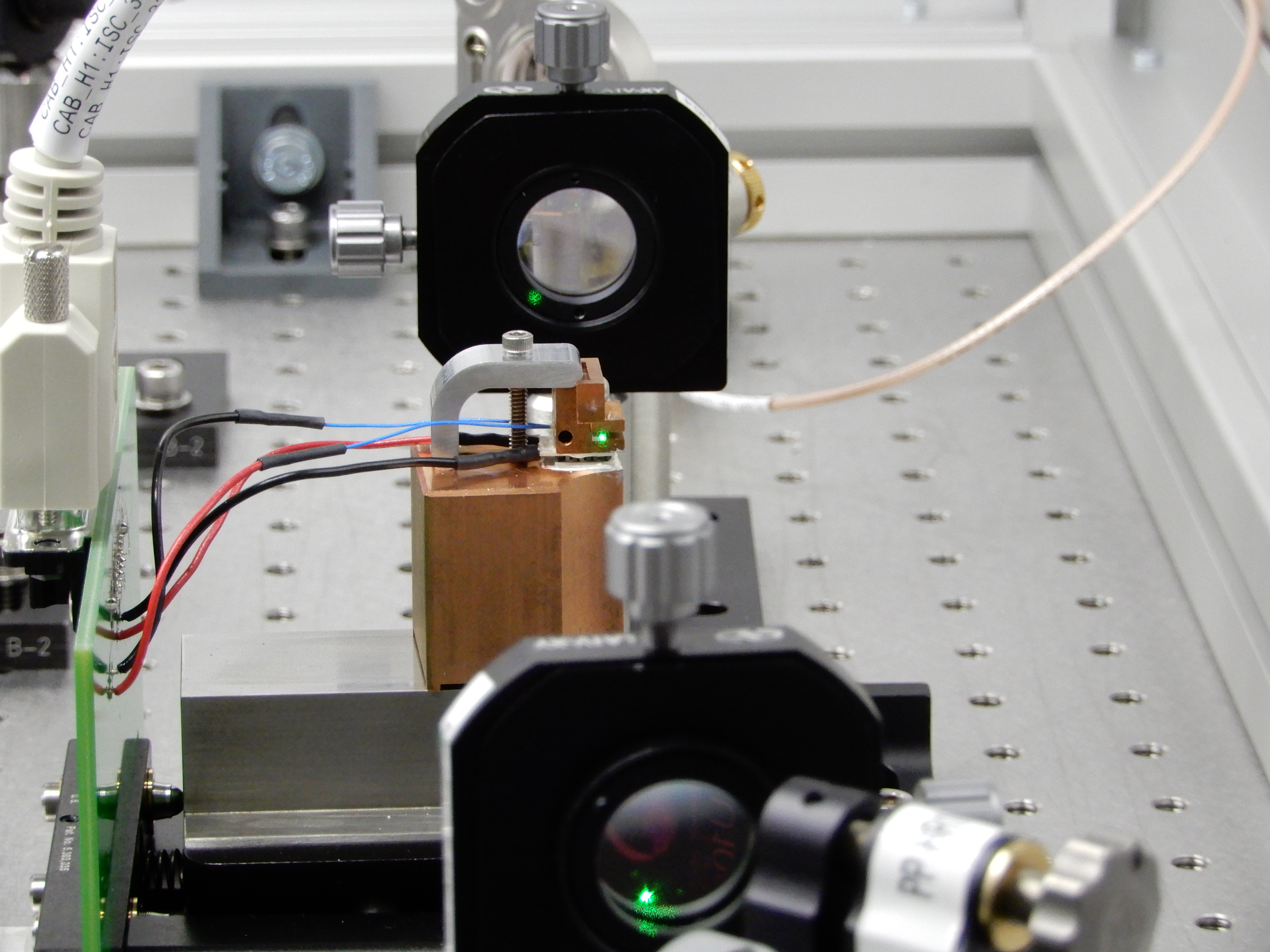
Photo of the beam position relative to the crystal mount.