M. Ball
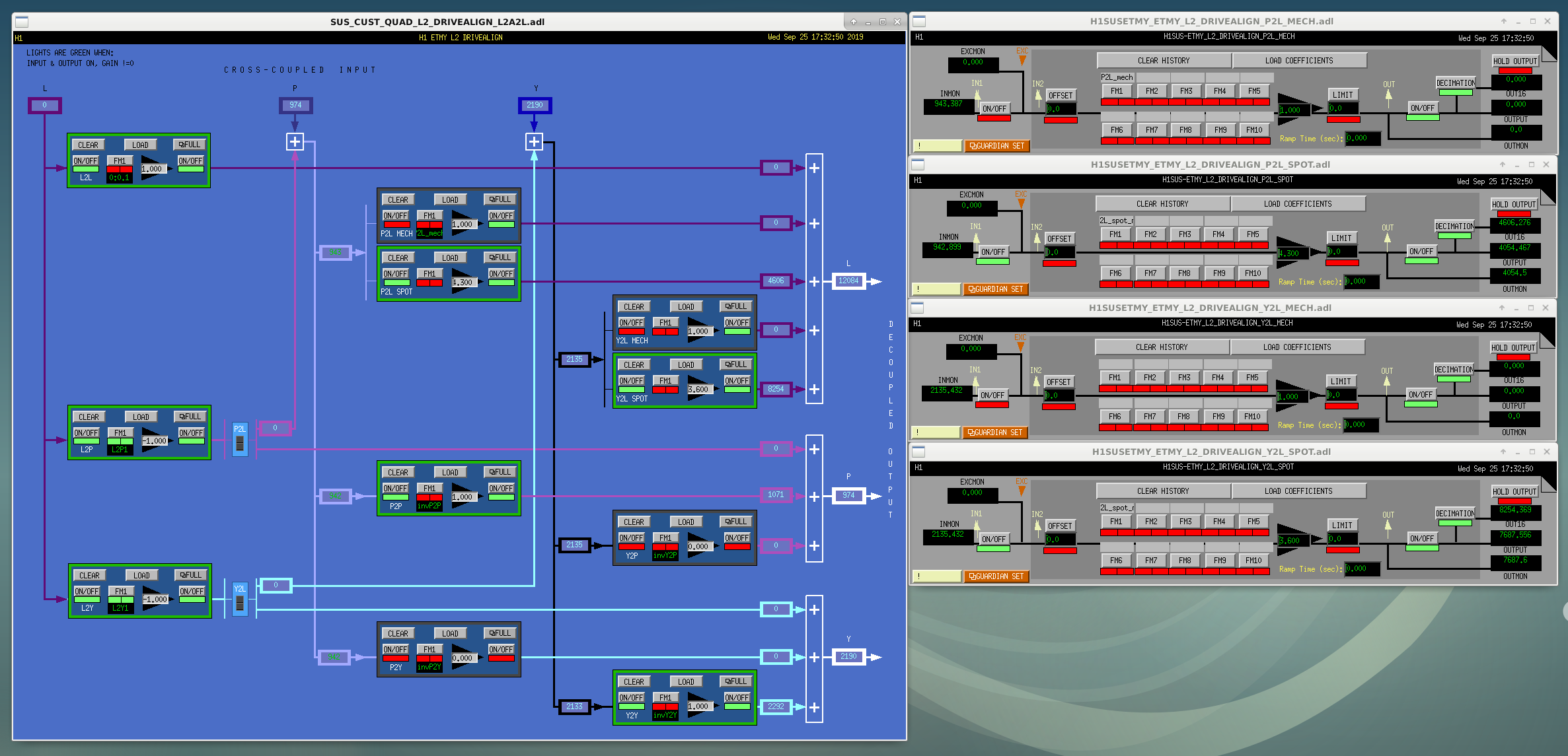
I have been working on angle to length decoupling filters for the quad L2 drivealign matrices. On Friday, September 20, during commissioning time, I installed these filters into the front end (all filters disabled currently). These filters can be activated in the L2 drivealign matrices for each quad suspension. I have attached a sample screenshot of the ETMY drivealign window with the P2L SPOT, P2L MECH, Y2L SPOT, and Y2L MECH filter bank windows, showing where these filters are located (filters are in all quad suspensions but the figure is just of ETMY).
For the pitch to length filters, the filters are located in the "P2L SPOT" and "P2L MECH" filter banks in the FM1 filter modules for ETMX, ETMY, ITMX, and ITMY. The P2L_SPOT_GAIN channel values will need to be changed as these filters are designed for this gain to be the beam pitch offset (in mm). In the current scheme, the P2L SPOT filter banks are active with just a scalar gain, and the P2L MECH filter banks are disabled. In the new scheme, both the P2L SPOT and P2L MECH filter banks will have filters active in them. The filters added to the P2L MECH filter banks account for suspension dynamics.
For the yaw to length filters, the filters are located in the "Y2L SPOT" filter banks in the FM1 filter modules for ETMX, ETMY, and ITMX. There is no ITMY Y2L filter as the current spot is centered such that any filter added would be multiplied by zero gain. Any future ITMY yaw offset in the new scheme would benefit from a similar filter. The Y2L_SPOT_GAIN channel values will also need to be changed to the beam yaw offset (in mm). There are no filters added to Y2L MECH since the QUAD model used as a basis for these filters does not accurately represent yaw cross-couplings with other degrees of freedom. Note that the attached drivealign screenshot does not have any filters in the Y2L MECH filter bank for this reason.
The gains in the current scheme and the new scheme are given below.
| Current scheme acqusition gain | Current scheme nominal low noise gain | New scheme acquisition gain | New scheme nominal low noise gain | |
| ETMX P2L SPOT | 0.85 | 4.3 | -0.52 | -15.97 |
| ETMY P2L SPOT | 0.85 | 4.3 | -0.52 | -15.97 |
| ITMX P2L SPOT | 0.85 | -3.965 | -0.51 | 21.76 |
| ITMY P2L SPOT | 0.85 | -3 | -0.52 | 17.17 |
| ETMX Y2L SPOT | 0 | 3.6 | 0 | -13.11 |
| ETMY Y2L SPOT | 0 | 3.6 | 0 | -13.11 |
| ITMX Y2L SPOT | 0 | 0.055 | 0 | -0.2 |
| ITMY Y2L SPOT | 0 | 0 | 0 | 0 |
Recall that two sets of values are required since lock is first acquired at one spot position then moved to the optimal spot position for nominal low noise.
These values for the new scheme are calculated using QUAD model transfer functions from the penultimate mass to the test mass as follows.
For PITCH: gain=-(P2l+G_P2L*L2l)/(P2p+G_P2L*L2p) where P2l is the PUM pitch to TST length transfer function from the QUAD model, G_P2L is the P2L_SPOT_GAIN used in the current scheme, L2l is the PUM length to TST length transfer function from the QUAD model, P2p is the PUM pitch to TST pitch transfer function from the QUAD model, and L2p is the PUM length to TST pitch transfer function from the QUAD model. This is evaluated at the dither frequency for that suspension. This gives the beam offset in meters; the filters are scaled such that the new gain should be this offset in mm.
For YAW: gain = -L2l*G_Y2L/(Y2y) where L2l is the PUM length to TST length transfer function from the QUAD model, G_Y2L is the Y2L_SPOT_GAIN used in the current scheme, and Y2y is the PUM yaw to TST yaw transfer function from the QUAD model. This is evaluated at the dither frequency for that suspension. This gives the beam offset in meters; the filters are scaled such that the new gain should be this offset in mm. Note that this expression does not include Y2l or L2y terms to match the form of the pitch expression. This is because the QUAD model used as a basis for these filters does not accurately represent yaw cross-couplings with length.
I have attached a pdf with properly formated numerical expressions for the new gain for each mass as functions of the gains in the current scheme at the current dither line frequencies.
Moving forward, I recommend that during a future relocking, these filters be activated for testing. To do this, Guardian would need to be changed to include these filters with the new acquisition gain values during "Prep for locking" and with the new nominal low noise gain values during "Engage soft loops".
I recommend measuring spectra of L3 length signals before and after as well as spectra of L2 angular signals with their coherence with DARM before and after these filters are enabled to see if the filters are behaving as they should.