[Rick Savage, Jeff Kissel, Timesh Mistry]
Parts from RDL
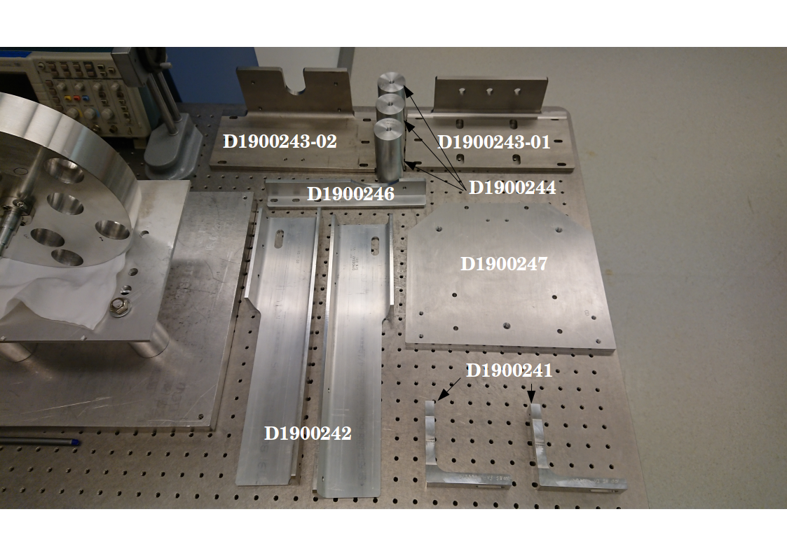
Today (02 October 2019) we received the NCAL mount parts from RDL. Most of the parts have arrived thus we proceeded to assemble the mount in preparation for the remaining parts.
We are still missing part number D1900245.
Assembly of the NCAL Frame
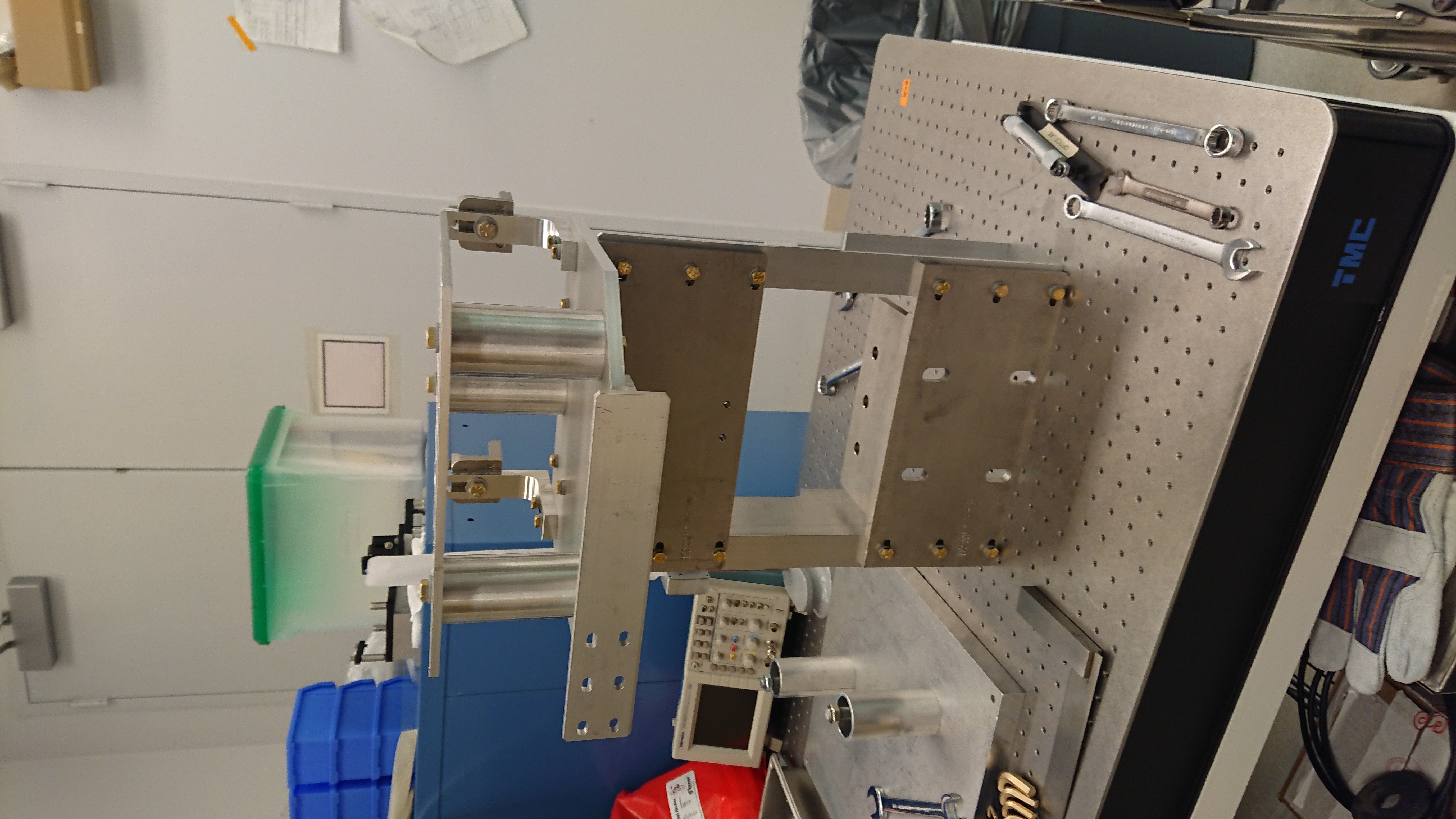
I assembled the NCAL frame in the optics lab in preparation for a fitment and clearance check at the X end station. The full process/assembly instructions will be detailed in another document however I will summarise the process I underwent to assemble the mount. The parts referenced can be found from the NCAL document tree or using the parts names quoted below (or in the figure 1). All parts are hand tightened but not torqued to specifications at this point and all the fasteners used are given in the full assembly CAD drawing D1900145. The final assembly (without the NCAL) looks is given in figure 2.
- Bolted D1900243-01 to D1900242 using 6x 1/4"-20 x 1" bolts and lock washers. Bolts are loose to allow for adjustment later.
- Bolted D1900243-02 to D1900242 using 6x 1/4"-20 x 1" bolts and lock washers. Bolts are loose to allow for adjustment later.
- Adjusted the assembly thus far, using a straight edge and spirit level to ensure correct alignment. Tightened bolts in a star pattern using 7/16 spanner.
- Bolted D1900247 onto D1900243-02 using 4x 1/4"-20 x 1" bolts and lock washer. Tightened bolts in a star pattern using 7/16 spanner.
- Bolted D1900246 to D1900247 using 4x 1/4"-20 x 3/4" bolts and lock washers. Tightened bolts using 7/16 spanner.
- Bolted D1900244 onto D1900247 using 3x 3/8"-16 x 1" bolts and lock washers. Tightened bolts using 9/16 spanner.
- Bolted D1900241 onto D1900247 4x 1/4"-20 x 1" bolts and lock washers. Tightened bolts using 7/16 spanner.
- Removed the NCAL base plate from the old mount and installed onto D1900244 using 3x 3/8"-16 x 1" bolts and lock washers. Tightened bolts using 9/16 spanner.
- Since the NCAL is currently fully disassembled, I bolted the bottom frame + side frame onto the top of the NCAL mount structure to give an impression of the final height.
- I attempted to install the Gibson Beam Clamps however, I found I had to use 1" bolts in Detail A of D1900145 since the 3/4" bolts are not long enough to securely hold the clamp.
- I removed the beam clamps and rested the NCAL mount horizontally.
Pressing Dowel Pins
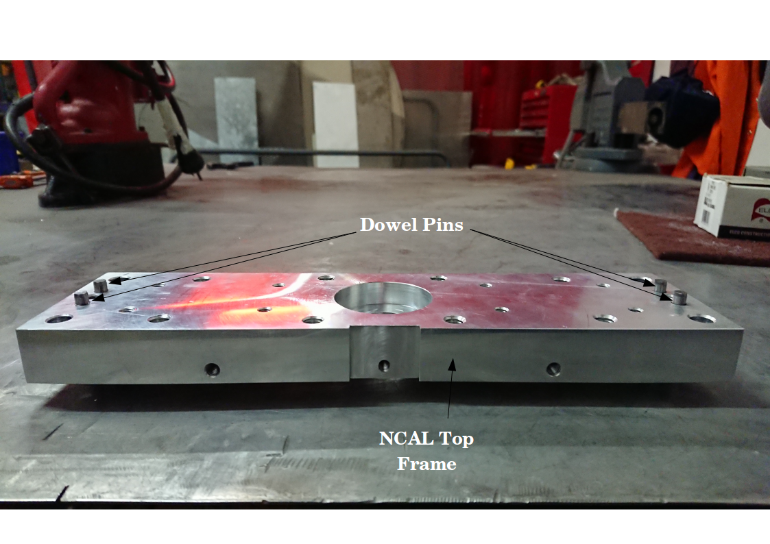
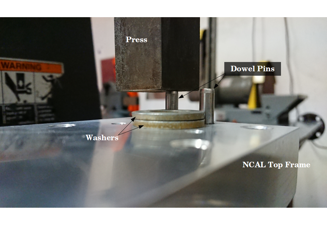
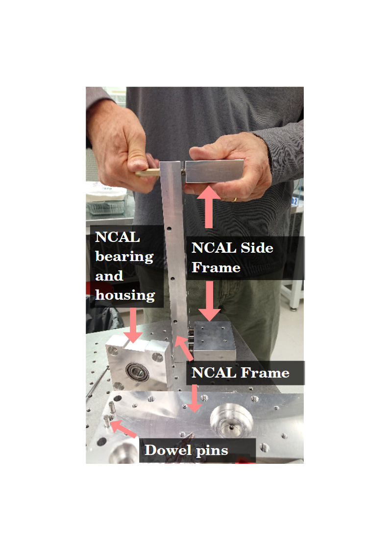
From LHO alog 52258, we had a few proposals to address the dowel pins on the top and bottom NCAL frames. We decided to partially press the dowel pins out (see figure 3). We used a press to push the dowel pins out and used washers to set the height of the dowel pins (see figure 4).The process in which we achieved this was:
- Placed the NCAL frame in the press, with the pins facing up, ensuring that there is sufficient clearance on the reverse side for the dowel pin.
- Placed the washers such that press will stop when it reaches the height of the two washers.
- Used the lever to apply force on the dowel pin and continue to press until the washers stops were reached.
- Released pressure on the pins and moved the unit to the next pin.
- Repeated steps 1-4 for the remaining pins.
We found that it required more force than expected to press the pins out. Upon closer inspection of the outer surface of the pins, it is clear to see that is had seized into the NCAL frame. We suspect that the tolerances, for the holes that the pins are housed in, are too tight.