
On Monday, old HAM6 OMC path septum window was uninstalled. We measured the wedge angle of that window using a laser pointer in the optics lab.
See attached for the setup. We used an eye safe lasr pointer that passed Peter King's inspection in the optics lab. We were clearly able to see the direct transmission and the first ghost beam, so we just measured the distance between these two beams at two different locations, and derived the relative angle between these two beams, from which we calculated the wedge angle.
The result is w=0.745+-0.022 deg.
See the attached comments for the details of the measurement and the calculation.
The spec is 0.75+-0.02 deg (D1101005) so this seems to be as per spec after all, despite that in the past we believed this to be more like 0.9 deg. (See the history comment attached to this one.)
Oh, and we confirmed that the mark on the flange was on the thickest side, as per the drawings D1101092 and D1101005.
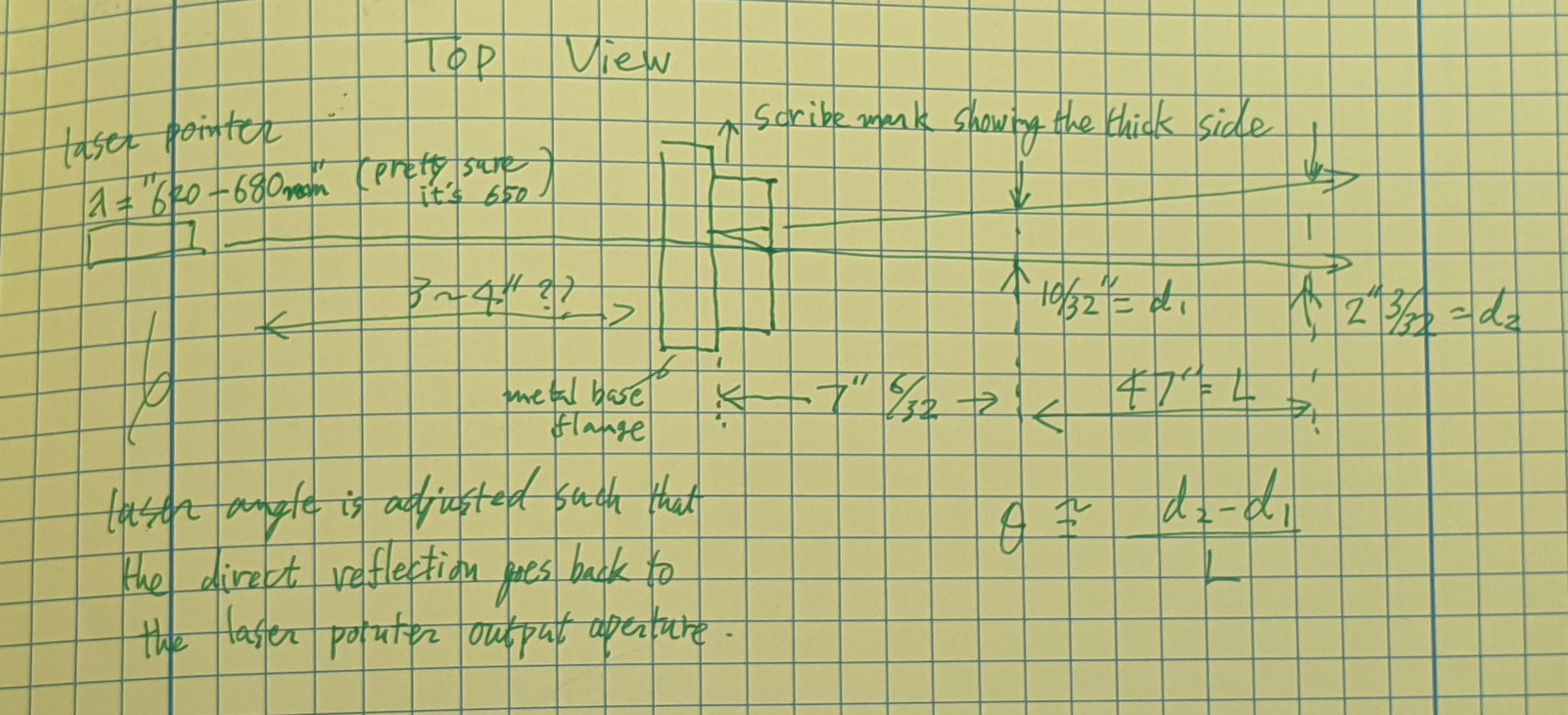
Setup, Measurement and Calculation details.
The incident angle on the first surface of the viewport was adjusted so the return beam goes back into the laser output aperture. I clain the incident angle to be 0+-10mrad, which hardly affects the result in any meaningful way.
The angle between the straight shot beam and the first ghost beam, theta, was measured using the distance between two beams measured at two different locations. Distance measurement was done using clean metal ruler with 1/64" gradation, and I claim that the maximum error that was possibly made for each measurement was 1/32".
Distance between two beams at the first location is
d1=10/32 +- 1/32 inches.
At the second location it is
d2=(2+3/32)+-1/32 inches.
Distance between the first and the second location L was
L=47+-1/32".
After combining errors, the angle between two beams is
theta~(d2-d1)/L=3.79E-2*(1+-0.03).
Taking only the first order of the wedge angle w, the angle between these two beams is very well approximated by 2*n*w where n is the refractive index (n=1.4566+-0.0008 for fused silica, lambda=650+-30nm). Second order error of w as well as the error for n are both much smaller than the 3% overall error in the angle measurement. Therefore
w=theta/2/n = 1.30E-3*(1+-0.03) rad = 0.745 +- 0.022 deg
History:
Nominal wedge = 0.75 deg.
Aug. 2014: Koji used a laser pointer and estimated it to be w~0.89 degrees (alog 13375), and updated the number to 0.91 deg later. This seemed to make sense (e.g. look at alog 13477).
Nov. 2017: When we rotated the window by 180 degrees, the beam position on OM1 changed by 23mm over the distance of 1930mm (alog 39504).
Thus the deflection by the septum window is 23/1930/2~6.0mrad=(n-1)w where n is the refractive index and w is the wedge.
Using n=1.4496 for fused silica at 1064nm, we obtain w~13.3mrad=0.765deg. Suddenly it looks closer to nominal.
Today: Using laser pointer in the lab, w=0.745+-0.022 deg.
Just to make sure, the one we measured is this one
| ASSY-D1101092-3 | HQ Wedged 6 in Septum VP | |
| 2-253V75--BULK-C30Q002 | Dupont O-Ring #AS568-253 Viton 75, V75 FKM, Inside Diameter 5.359", Cross Section 0.139" | |
| D1003207-V1-00-C6Q002 | High quality, 6in Viewport, Viewport Spacer | |
| D1101005-V1-12KWZ-S5-1363-S5-1364-0015 | aLIGO, high quality, .75 deg wedged, 6" Viewport, AR-1064 nm Optic | |
| D1101115-V5-00-0007 | High Quality, 6" Viewport CLAMP, wedged | |
| D1101117-V3-00-0006 | aLIGO Septum Viewport FLANGE |
listed in alog 52377.
The new one that was installed on Monday, i.e.
| ASSY-D1900198-001 | LHO Yawed, Septum Viewport Assy | |
| D070082-V1-00-0006 | ELI Septum Window | |
| D1101117-V3-00-0022 | aLIGO, Septum Viewport Flange | |
| D1900240-V3-00-0001 | aLIGO, VE, HIGH QUALITY VP, WEDGE CLAMP | |
| D1900327-V1-00-0002 | aLIGO, VE, HIGH QUALITY VP ASSY., YAW ADAPTER |
has a wedge angle of 0.727 degrees according to Alena. That one was not obtained by beam angle but by mechanically measuring the thickness of the arrowed edge of the window (thickest) and the edge opposite to that (thinnest).