[Corey Gray, Timesh Mistry]
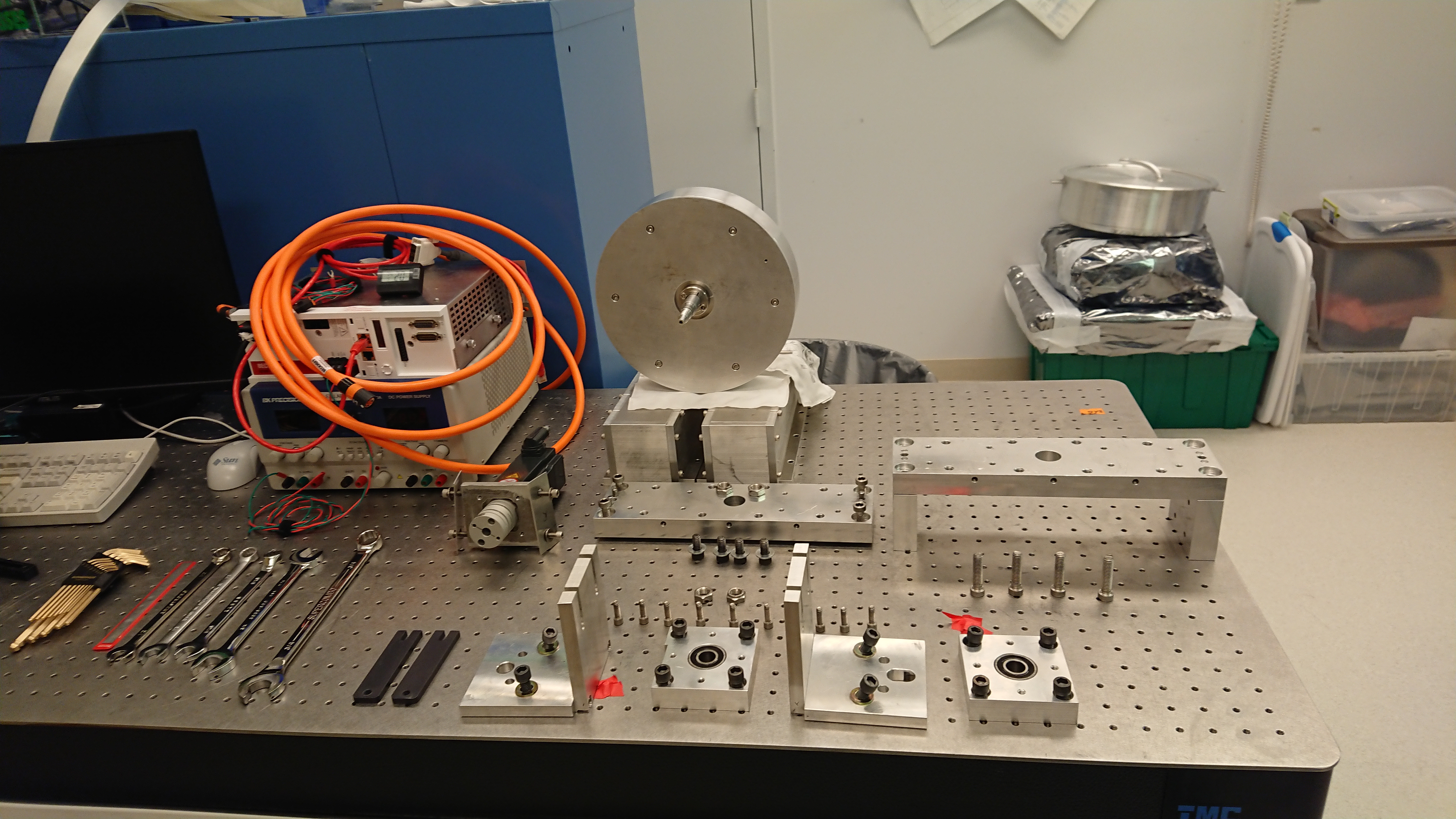
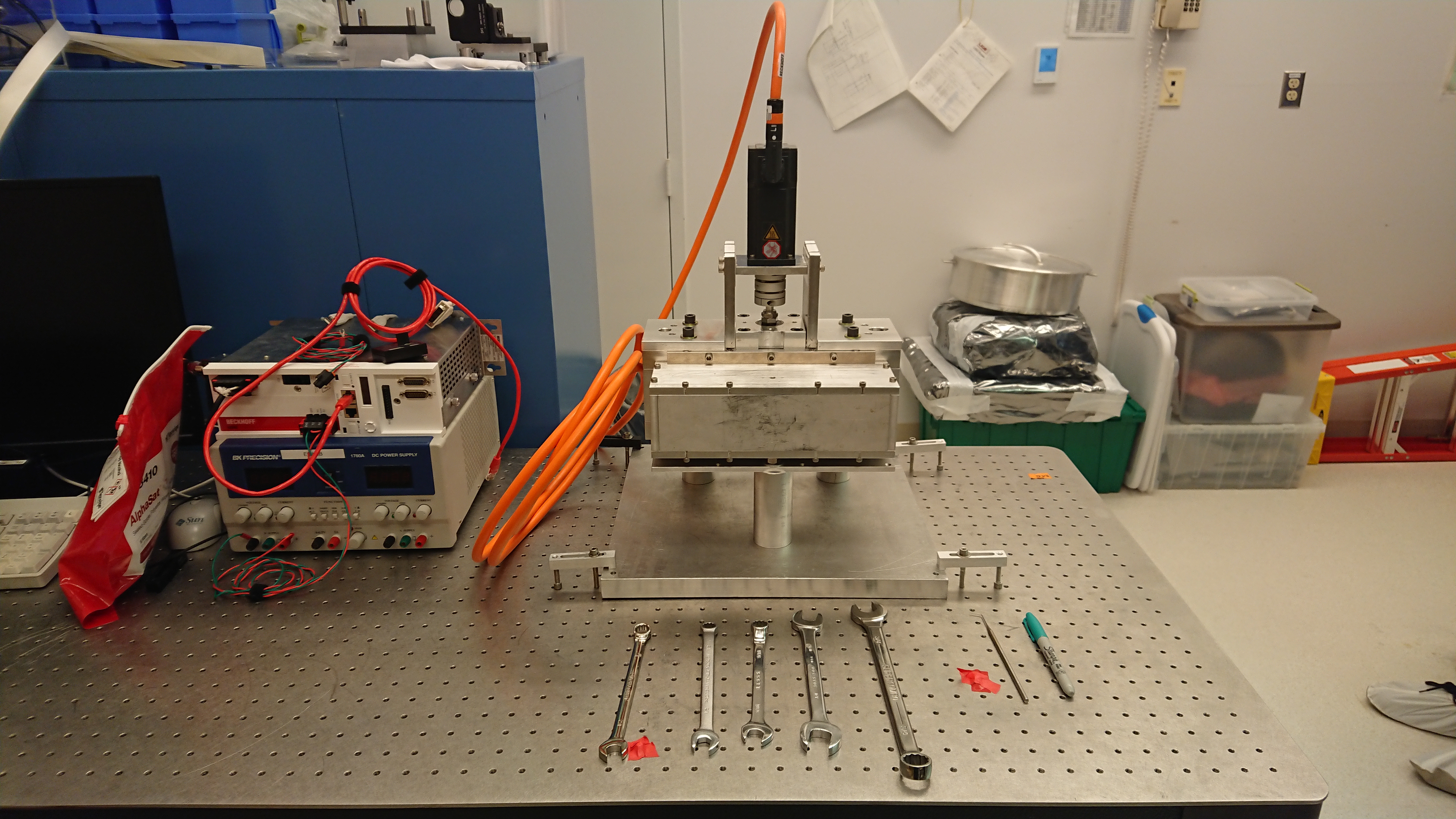
Delayed post from 15th Ocotber 2019, we have disassebled and re-assembled the NCAL, hopefully for the final time.
NCAL Dissassebly
================
Using 3mm allen key, unbolt the grub screw holding the motor coupler to the NCAL shaft. Do not undo the bolt fully, only enough so that it is not clamping the coupler to the shaft.
using a 3/16 allen key, unbolted the 4 bolts that hold the motor to the "L" bracket. Do not undo the bolts fully, enough so that the motor can slide off the shaft. The metal shim are not uniform and thier placement is important.
They are marked left and right with respect to the breaing housing assembly cut out.
Using a 5/16 allen key, remove the bolts holding the "L" brackets to the NCAL top frame.
Using a 5/16 allen keym remove the bolts bolding the NCAL plate to the NCAL lower frame.
Lift the NCAL up and off the NNCAL plate, ensuring the shaft does not impact any surfaces. Place the NCAL on its' side and using a 3/16 allen key to remove the bolts holding the side covers.
Remove the side covers and place the NCAL upright, using the sidecover to rest the NCAL upon.
Using a 5/16 allen key, remove the 4 bolts holding the top bearing assembly. The bearing assebly will lift off.
Using a 5/16 allen key, remove the 4 bolts that hold the top frame to the side frame.
Insert a bolt between the alignment pins and, using a few drops of IPA, wind in each bolt evenly until the top frame is loose.
The rotor can lift out and using a 3/16 allen key, the collars can be removed from each side of the rotor and the collars will slide off and shaft will pull out.
Insert a bolt between the alignment pins and, using a few drops of IPA, wind in each bolt evenly until the top frame is loose.
Use 5/32 allen key to remove (6) #10-32 bolts & remove Back Plate (bolts & collar were cleaned with alcohol wipes).
Use 3/16 allen key, to remove (2) 1/4-20 attachement bolts & (1) 1/4-28 collar bolt of Bottom collar (bolts & collar were cleaned with alcohol wipes).
NCAL Assembly
==============
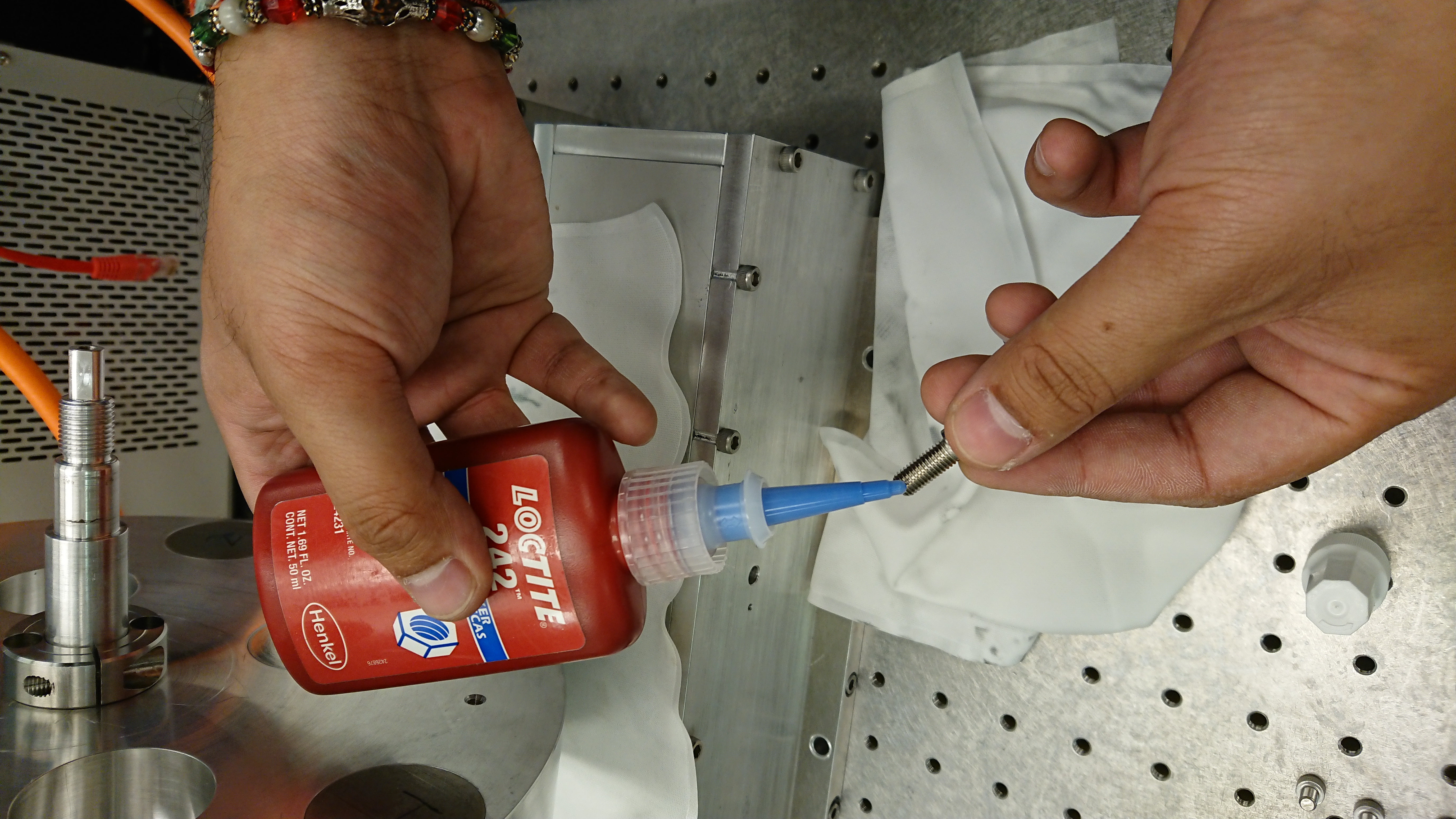
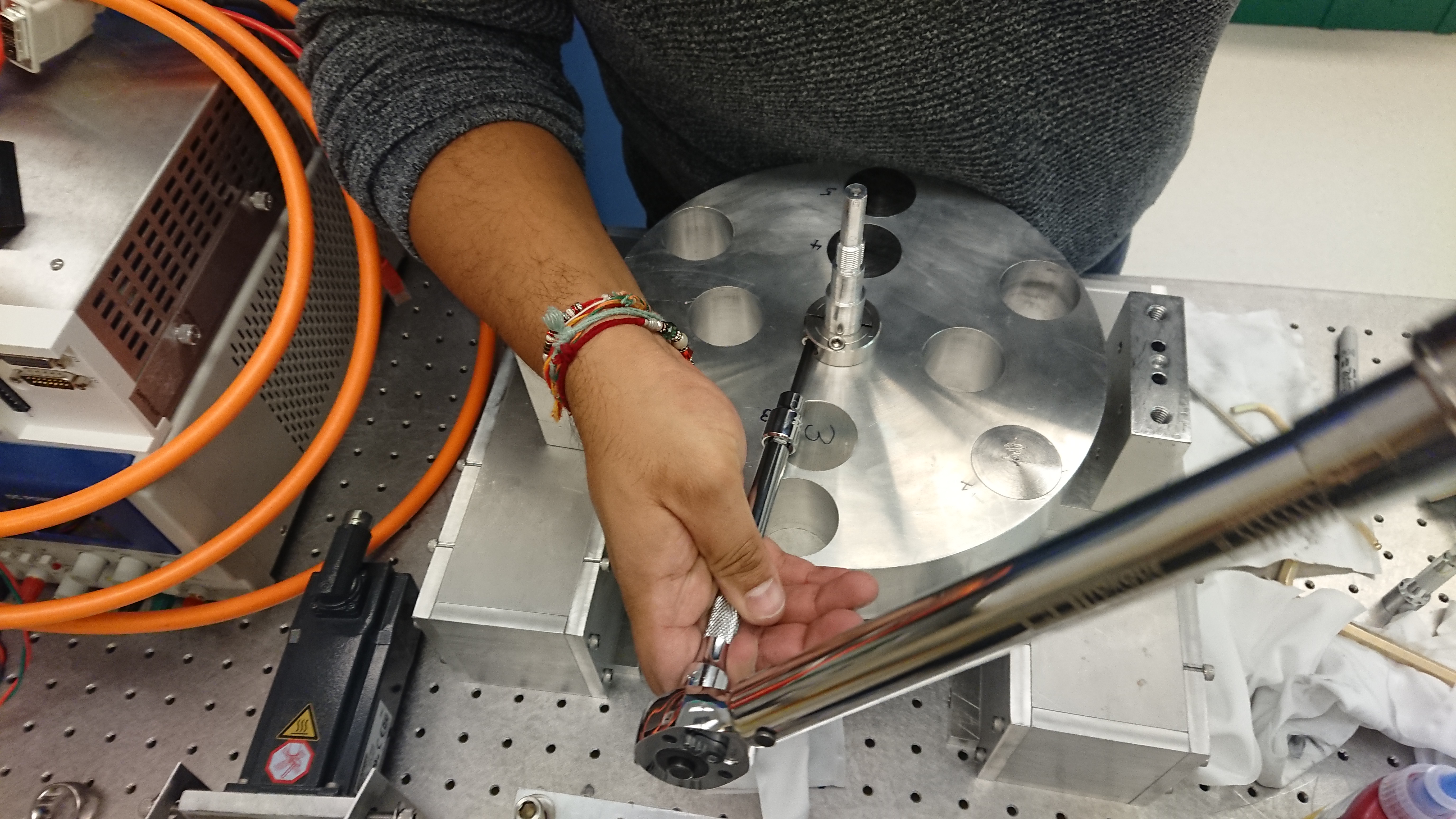
Install Bottom Collar. Apply Loctite to (3) Bottom Collar bolts (1/4-20 & 1/4-28) & torque down all three bolts (torque value of 7 ft-lbs used). Used an extension w/ bevel for torque wrench.
Install Back Plate. Apply Loctite to (6) #10-32 bolts & use them to attach the Back Plate. Turn bolts slowly by hand and check that Back Plate is installed flushly with the Main Rotor. Torque all (6) bolts hand tight (or 2.6 ft-lbs).
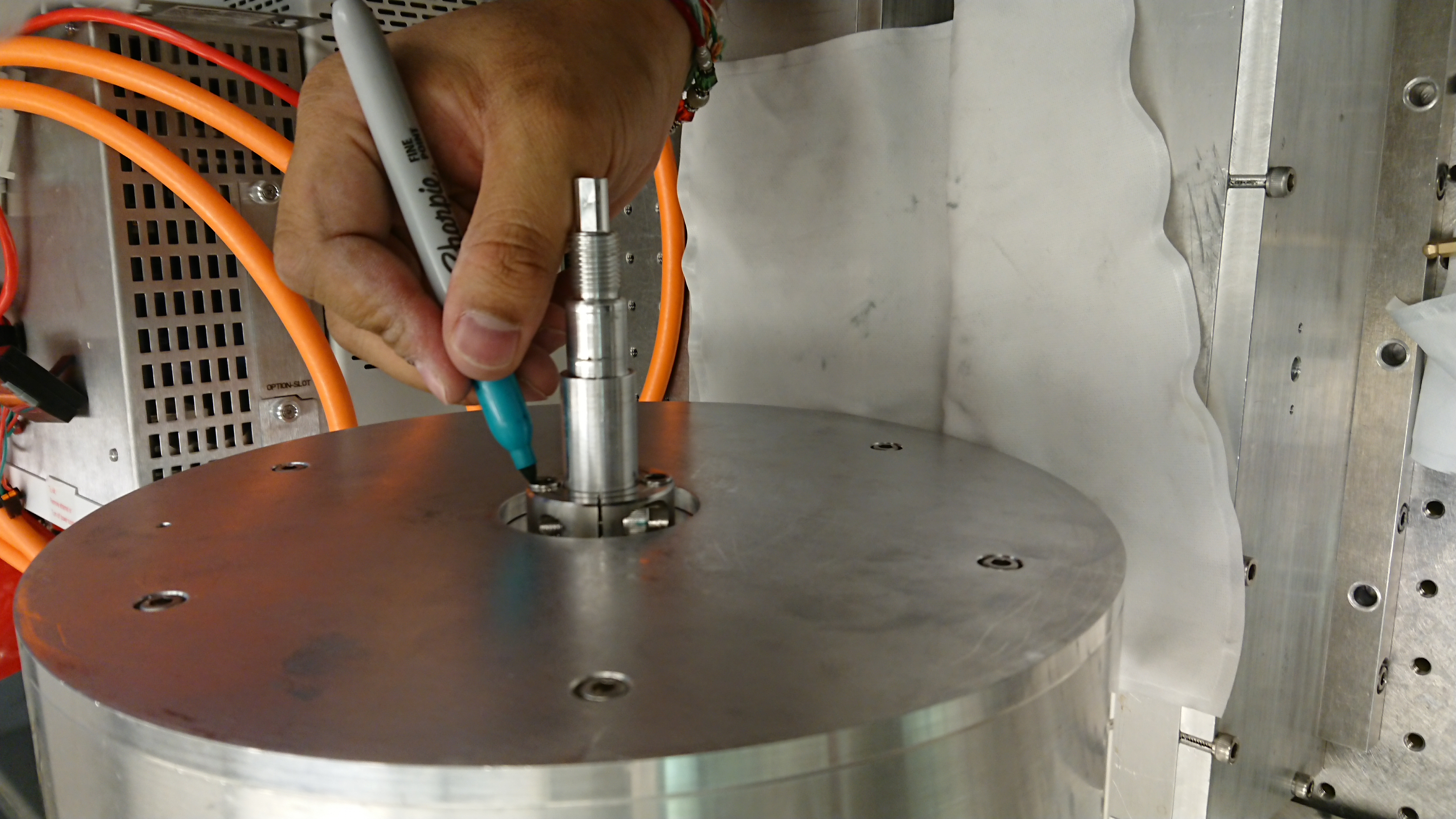
Sharpie marker used to mark bottom bolts which were torqued.
For Lower Frame assy, apply Loctite to (4) 3/8-16 bolts (confirm bolt size!), install, and torque them to 20 ft-lbs.
For Lower Frame assy, install Lower Bearing Assy loosely (for fit onto Rotor Shaft).
Install Top Collar. Apply Loctite to (3) Top Collar bolts (1/4-20 & 1/4-28) & torque down all three bolts (torque value of 7 ft-lbs used). Used an extension w/ bevel for torque wrench (see photos).
Lift Main Rotor Assy, place pair of shims between Main Rotor & Lower Frame Assy.
Install Upper Frame Assy. First line up "alignment marks" of Upper & Lower Frame Assys. Secondly, use pins of Upper Frame to attach to Lower Frame. Finally apply Loctite to (4) 3/8-16 bolts (confirm bolt size!), and slowly tighten
bolts together at roughly 1/4 turn at a time. When there is contact between Upper/Lower Frames, torque to 20 ft-lbs.
Loosely install Top Bearing Housing (for fit onto Rotor Shaft). Make sure to line up cut out of Top Bearing Housing with cut out of Upper Frame.
Confirm play of shaft is good & there is no wobbling.
Once shaft is acceptable, torque (4) Top Bearing Housing 3/8-16 bolts (confirm bolt size!) to 20 ft-lbs.
Install Top Shaft Nut & Lock Nut. Install such that the distance from the top surface of Main Rotor & bottom surface of Upper Frame is about 7mm.
Lift Assy, as is, to now access Bottom Bearing Housing.
One bolt at a time, remove (4) Bottom Bearing Housing 3/8-16 bolts (confirm bolt size!), apply Loctite, reinstall, and then finally torque all (4) bolts to 20 ft-lbs.
Install Bottom Shaft Nut & Lock Nut. Install such that the distance from the top surface of Main Rotor & bottom surface of Upper Frame is about 6-7mm.
Lock upper & lower shaft nuts by using a pair of 3/4" spanners.
Install both Side Covers. Each one needs (6) 1/4-20 bolts and they are only torqued hand-tight.
Attach NCal Assy to Base Plate with (4) 3/8-16 bolts (confirm bolt size!) and torque them hand-tight.
NCAL General Notes
==================
Reference marks built into the NCAL as part of the design for alignment when surveying it in.
Shorter dowel pins for easier and disassembly and reassembly.
Better tolorances on bolt holes and bearing alignement.
Better consideration for users who have to assemble/disassemble unit.
Have a defined height for the NCAL motor on the L brackets.