vladimir.bossilkov@LIGO.ORG - posted 09:50, Tuesday 22 October 2019 - last comment - 15:54, Tuesday 22 October 2019(52618)
20191022 Search for Temperature Dependance in Pcal Photodetectors
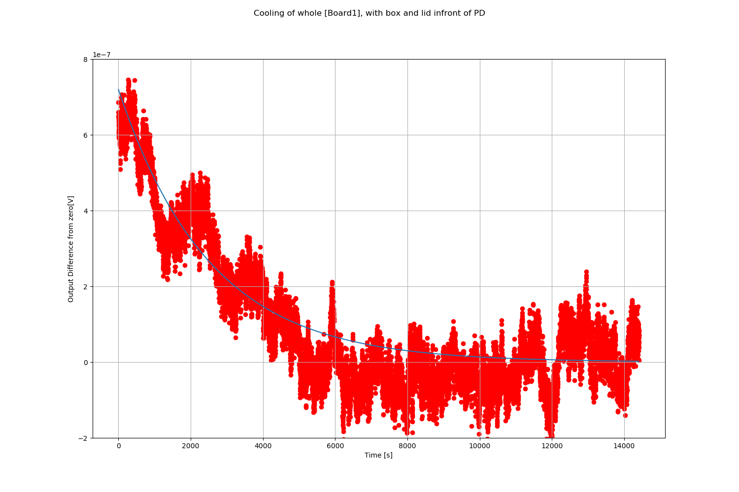
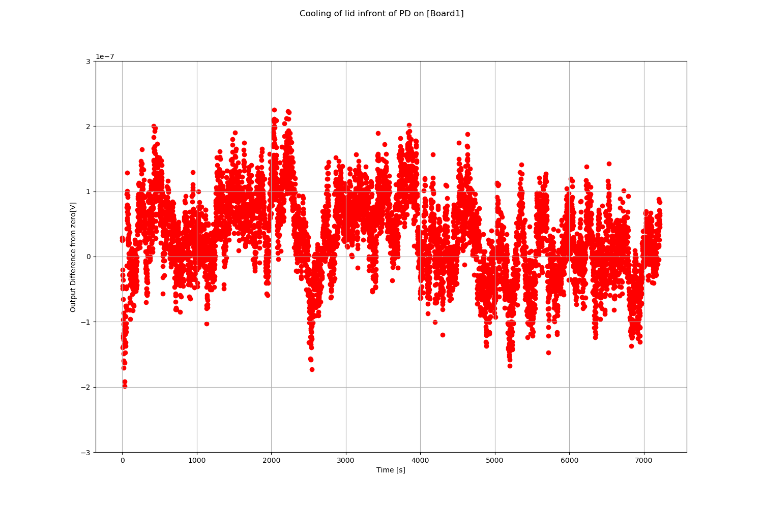
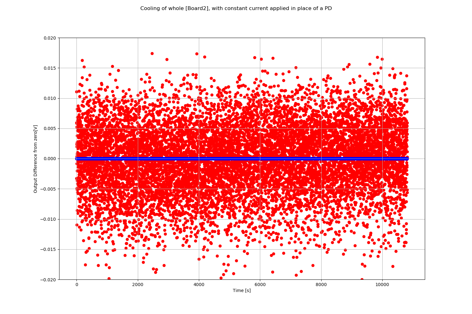
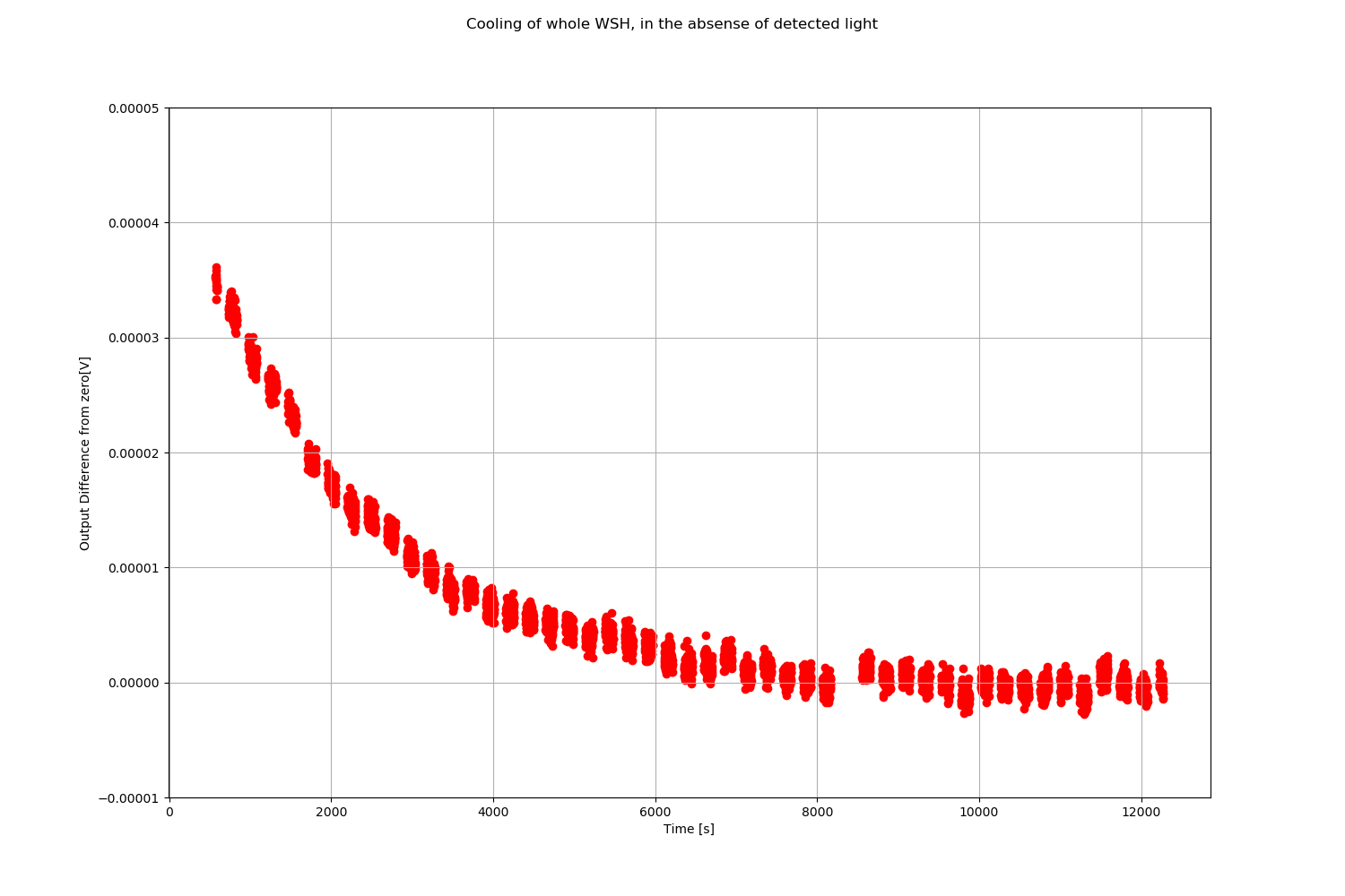
Vlad and Niko

We have tasked ourselves to some of the backup hardware to search for what causes apparent temperature dependence on the output of the photodetectors used in integrating spheres for the Gold and Working standards (GS and WSx, x is the site for which the instrument is for) for calibrating optical power in all of the GW detector sites.

We are trying to explain the temperature dependence seen in [Zero_light_voltage_change.png], and [Normal_operation_voltage_change.png], in both images the DC offset has been subtracted. Temperature dependence was observed with no laser input to the integrating sphere with the cap attached to the front, and also when in normal operation when the whole integrating sphere was heated to 35 deg. C and allowed to cool. The magnitude of Voltage change due to temperature when there is laser light also incident on the detector is about 100x more.

We have two available circuits for this initial test.
[Board1], with only the photodiode (PD), which requires an external transimpedance amplifier (set to 50 times the gain of the GS) to get a voltage output.
[Board2], with no PD, which requires an external current source (set to the typical current seen in Pcal measurements) to get a voltage output.

We first looked at the output of the PD alone:
[Exp1.png]: We heated up the whole box containing [Board1] to 35 deg.C, and looked at the response. This setup observed significantly better noise performance than the GS (roughly 10 times less noise, when the data was corrected to equivalent gains), which We observed some temperature dependence, and the solid line plotted is the predicted dark current from the PD as it is set up, while the box is cooling [caveat: function for solid line was estimated from documentation of a different but similar PD. The data sheets for our PD have no information at all about its performance in photovoltaic mode (zero bias voltage)]. The good fit makes us confident we know the source of this signal, and is much smaller than what was seen in the experiments done in the past [Zero_light_voltage_change.png].
[Exp2.png]: We heated up the lid in front of the PD to the box containing [Board1] to 35 deg.C  Vlad predicted the PDs should be sensitive to changes in the black body radiation of objects close the to PD - unfortunately no change in output was seen in this experiment. This rules out his theory, unless PD behaves differently somehow when illuminated with some optical power (some non linear output behavior). Looking at the data, one could argue that the PD warmed up some time after placing the lid in front of it, giving a slight change to the response, but this could easily be some ambient effect.

Next we look at the output given a constant current instead of a PD, to the circuit board, [Board2]:
[Exp3.png]: We heated up the whole box containing [Board2], and looked at the response. The data from [Board2] is in red, and the data from the GS is in blue, and DC offsets have been subtracted. Unfortunately our experiment is swamped with noise (roughly 10^6 times more peak rms noise than the GS), and the effect we are looking for is somewhere deep in that noise. Our box also cooled much faster than experiments done before since it was sitting on a table (completely cool in about 10 minutes). In the future we will lift it to make the cooling slower. The noise should not be due to the current source, going by it's specifications and our measurements of its output before the experiment. The board has a different Op.Amp., with a capacitor missing on its power supply, at the output point of the circuit, compared to the specification in D1300210. Talking with Niko, all the boards were put together by the same company and should be identical, unless this is some weird experiential board.

Future plan:
1)Resolve Noise issue of [Exp3]:
	a)Niko will chase up circuit boards assembly company to double check what is on the circuits and if some were different
	b)We can check frequency of noise in [Board2]- if high frequency could be due to the missing capacitor
	c)Maybe one board had faulty components and was set aside?
	d)Open a Working standard to check and compare is the last option
2)Repeat [Exp3] and see if we get the temperature dependence that we expect, with a noise level at least comparable to the GS
3)If we see the expected temperature dependence from [Normal_operation_voltage_change.png]: we can use preheated tools to apply pinpoint heat to individual components and find what is most susceptible to temperature dependence
4)If we do not see anything on [Board2], we go back to [Board1] and repeat [Exp1] and [Exp2] in the presence of optical light (ie mounted on an integrating sphere) to confirm the outcomes of [Exp1] and [Exp2] in the presence of an optical signal.
5)If we still see nothing - perhaps temperature dependence is not what we should be looking at. Ethan Payne (fellow who was looking at some of this data before me) makes a point that what we see could be a humidity dependance, though testing that is much more difficult.
Images attached to this report

Comments related to this report
[Board2] got a new Op.Amp and capacitor after some excellent soldering by Niko. Noise is gone, and we'll continue what we were doing tomorrow.