[Gavin Timesh]
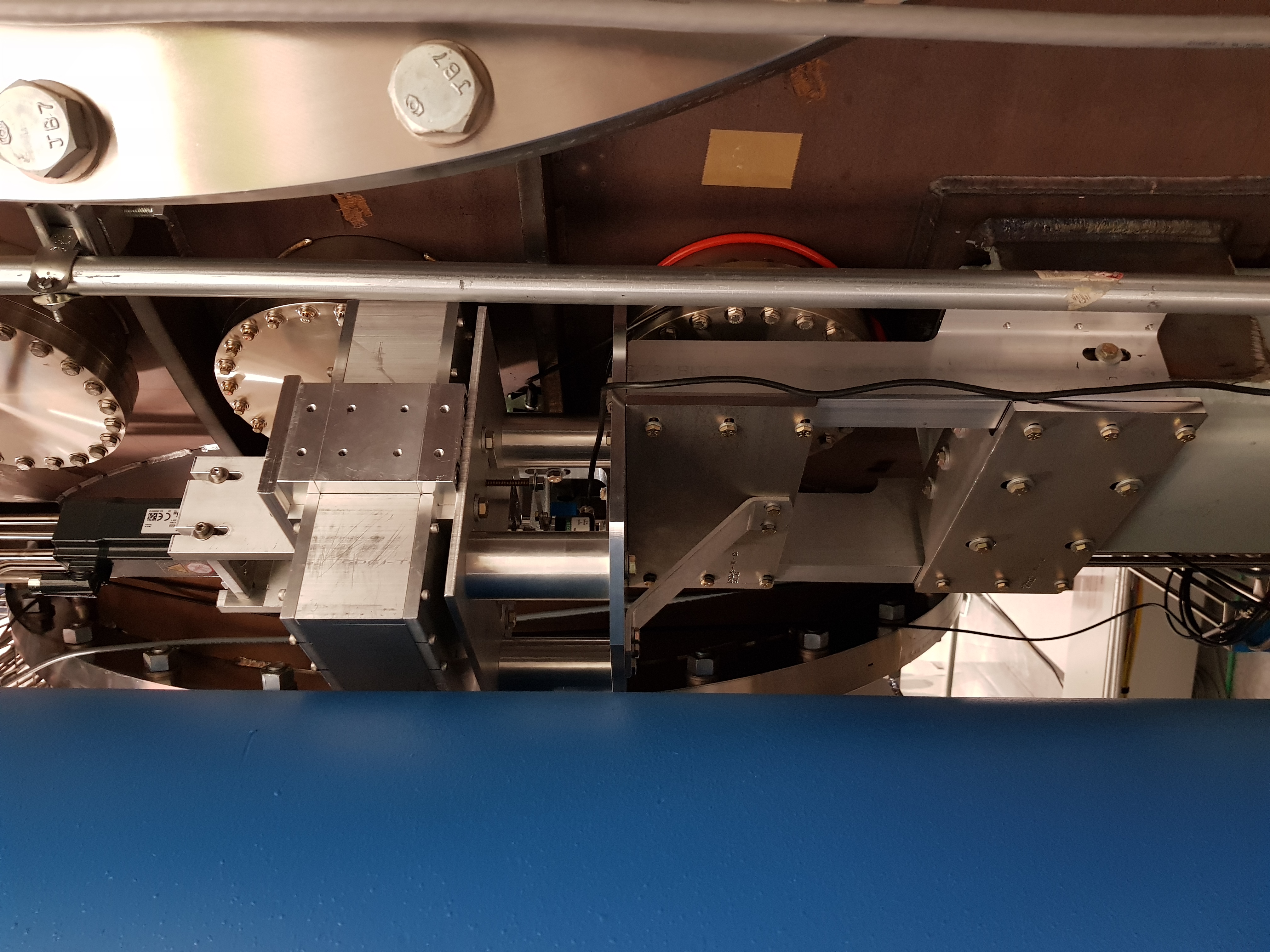
With permission from the comissioning team, we went to the X-End and the NCAL Prototype has now been installed.Pictures to follow later.
There were a lot of factors that lead up to the final install at the end station and there are still plenty of things to do but the goal of having the NCAL at the end station by the end of the O3 commissioning break has been achieved.
Drilling the BSC Pier
[Kyle, Bubba, Rick, Ethan, Gavin,Timesh]
To ensure accurate location of the drilled and tapped holes, we doubled checked the alignment of the drill fixture and the NCAL mount. We found that the holes still matched well between the drill fixture and the NCAL mount. During the drilling process, the fixture stayed relatively affixed, with very little movement and only required a small adjustment half way through the drilling process. Tapping the holes was relatively easy. The change to use fine threads instead of coarse threads makes the tapping process easier as well as increasing the strength of the fixing (in shear and tension) and less susceptible to loosen under vibrations. We decided to drill and tap for 5/16"-24 x 1" holes on the BSC pier. This is for 2 reasons: 1) To increase the strength of the fixings 2) To overcome the large slot size, that would have resulted in using stacks of washers had we use 1/4-20 x 1" as originally called out however, now we can use 1 lock washer and a bolt as normal.
To start with, the drill fixture (jig) had drill bushings installed that would allow the drilling of a hole suitable for a 1/4-20 bolt. During the drilling process, after each hole was drilled successfully, we used a metal dowel pin placed though the drill bushing in the fixture and through the newly drilled hole to pin the fixture in place. This would prevent the fixture moving while the other holes are being drilled. Once all the holes were drilled, the dowel pin were removed one by one. For each pin that was removed, a new drill bushing is inserted to drill a 5/16"-24 bolt hole and the hole was drilled. Since a 1/4-20 sized pilot hole now exists, the drilling process of opening up the hole to 5/16-16 is easy to do. After which, a tap bushing replaces the drill bushing and the hole is tapped for 5-16"-24 threads. Once the hole is tapped, a bolt is screwed in a finger tightened to the tap bushing to hold the drill fixture in place. The steps of removing the smaller bushing, inserting the bigger bushing, tapping and bolting are repeated until all 9 holes are completed.
After the drilling and tapping was completed, all the bolts were undone and the drill fixture was removed. The bolts were all inserted into the pier and wound in fully to clean the newly made threads and IPA was used in conjunction to lubricate the threads and help remove dirt/debris. Once we were satisfied the threads were clean, we removed the bolts and mounted the NCAL mount onto the pier. The drilled and tapped holes align to the holes on the NCAL mount and, using lock washers, the NCAL mount was bolted to the BSC pier. The mount was fully assembled up to the stage where the NCAL would be abled to be lifted onto it. The bolts have yet to be torqued however they are tight.
First Installation Attempt on 24th October 2019
[Ethan, Timesh]
We went to the X End to attempt to install the NCAL onto the mount that has already been bolted onto the BSC pier. When placing the NCAL upon the mount, we found that we cannot bolt the NCAL to the NCAL plate. We are ~2mm short of being able to bolt the NCAL down. This is because, the NCAL cover is touching the flange bolts and there is not more room to move the NCAL. The solution is to slot the bolt hole on the NCAL plate. This would allow the NCAL to translate towards and away from the chamber giving greater flexibility in the NCAL positioning on the NCAL mount. The draw back of this is that there is reduced repeatability to have the NCAL in the same place each time it is removed and installed. The distance of the NCAL to the test mass must have an uncertainty of less than 1cm otherwise the uncertainty in the force coefficient rises steeply.
Testing the Optical Encoder
[Timesh]
The optical encoder allows the rotor shaft to be piped into the front end DAQ at a higher rate then the typical slow rate that the Beckhoff systems are recorded at (since the Beckhoff signals are encoded into EPICS which is fixed at 16Hz sampling rate). This is not an upgrade but a part of the intended design as specified in the NCAL FDR and we can go as far as 65535Hz if we wanted to. The reason for having a faster rate than 16Hz is to have good phase resolution. With 1 kHz sampling with the NCAL at 30Hz, you will have about ~ 360/(1024/30) = 10 degrees of phase resolution. This signal can then be used to take transfer functions with other sub-systems in LIGO as well as provide a way of calculating the force coefficient from the NCAL to the test mass in the front end.
I had issues setting up the optical encoder however after a lot of help from Krishna, the commissioners and the EE lab people, I was able to get it working. The demon tweak was removing the power supply ground to the satellite box for the encoder. When I plugged the satellite box power, I had also connected the power supply ground to the satellite box which was injecting noise as well as not the correct way to supply +/- 15V to the satellite box. Once the issue was solved, the optical encoder was connected to the lower end of the NCAL shaft. Spinning the NCAL at 3148 counts (30Hz), the Beckhoff software reports 3147 +/- 1 counts, the frequency as measured on the oscilloscope by the optical encoder is 30 +/-0.6 Hz from a +/-10V sawtooth signal. As the NCAL spins up and down, I can see the phase of the sawtooth wave signal change accordingly and accurately measures the spin frequency.
Second Installation Attempt on 31st October 2019
[Gavin, Timesh]
While the IFO was struggling to lock, we were given permission to go to the X end to install the NCAL. We took the NCAL plate that had the required bolts holes slotted by Tyler as well as the rest of the NCAL system. This included the NCAL PC, the motor controller, the required cables and the motor.
We attached the NCAL plate to the NCAL mount first before lifting and mounting the NCAL onto the NCAL plate. The NCAL has been fully assembled such that is has the optical encoder attached as well as the Tungsten Masses installed in the rotor. The slots now allowed us to move the NCAL away from the flange bolts and bolt the NCAL to the NCAL plate, securing the NCAL in place. We tighten up the bolts with alan keys and spanner, with the aim to torque these down at a later time.We also installed cover plates over the exposed NCAL shaft and motor coupler. This is made of sheet metal but we will look to replace this with imact resistant acrylic. We also have the rigid coupler installed that couples the NCAL shaft to the direct drive motor. We will explore using a flexible coupler as this may reduce the stresses on the motor due to misalignment of the NCAL shaft to the motor, this increasing the lifetime of the unit.
In addition, we installed and ran the cable from the Beckhoff motor controller to the NCAL but the cable has not been connected as of yet. Moreover, we installed the PC in the EE bay and connected it to the network. We connected the NCAL computer to port 9 in the EE rack. There will be no data coming though the front end as the Beckhoff Channels are ready but not been added to the front end yet since this would require a front end restart. Moreover, we connected the grey satellite box to the optical encoder but we were unable to locate the BNC cable that runs the signal to the H1CALEX chassis. This will have to be done at an opportune time ot during a Tuesday Maintenance.
We removed all of our tools and equipement from the X end station since it is no longer necessary to have all the equipment at the end station now. The surveying equipment is still in place and is ready to survey (IAS) the NCAL to get the final position number of the NCAL to the Test Mass. We ran out of time to test power and comms so this will have to be done later.
Things to Do
IAS NCAL
Complete cabling
Test power and comms
First test spin (either over network or directly thought the Beckhoff)
Test NCAL shut down procedures.
Test spin using the network
Install MuMetal shielding
Magnetic, acoustic and vibrational coupling tests with PEM
Test different motor couplers
Install impact resistant acrylic shield