J. Oberling, R. Savage
Quick Summary
Max TPD I could get before any changes was ~3.6V. Nothing wrong with the FSS AOM, measured a diffraction efficiency of 75.5%. We found the FSS EOM alignment off and the beam clipping on the output aperture of the EOM housing, causing a 2nd beam in the FSS path. Fixing the EOM alignment issue took care of the 2nd beam and we were able to get the RefCav TPD up to ~5.0V. We also changed the ND filter on the RefCav Refl camera, centered the RefCav cameras, and installed a cover on the PMC voltage terminals. By measuring the crossover and the OLTF, we set the FSS loop gains to a common gain of 20 and a fast gain of 16. At the end of the maintenance window we noticed that the loop was having difficulties locking. I lowered the fast gain to 12 and things looked better, but was still not locking. I turned the FSS autolocker OFF then immediately turned it back ON and the loop locked right away without issue; I returned the fast gain to 16. RefCav TPD is currently reading ~4.7V. I expect this to drift some as the PSL enclosure temperature returns to normal; if necessary I can tweak the beam alignment at the nex available opportunity (earthquake, next maintenance window, etc.).
Details
This morning we tuned up the FSS path on the PSL table, to fix the drop in RefCav TPD we've been seeing. Before going into the enclosure I tweaked the beam alignment into the RefCav using our picomotor-controlled mounts; I started with a TPD of ~3.0V and ended with a TPD of ~3.6V. This is well below both my adjustment from last week (TPD = 4.8V) and my adjustment from October 14th (TPD = 5.4V), which definitely indicates something is off with the FSS path.
When we last tuned the FSS path in May the AOM was our primary culprit, so we started there. Nothing looked out of the ordinary; no obvious misalignment, no "structure" on the beam visible on an IR viewing card as last time. We measured the diffraction efficiency:
- Pin, AOM = 143mW
- Pout, AOM = 108mW
- Diffraction efficiency: 75.5%
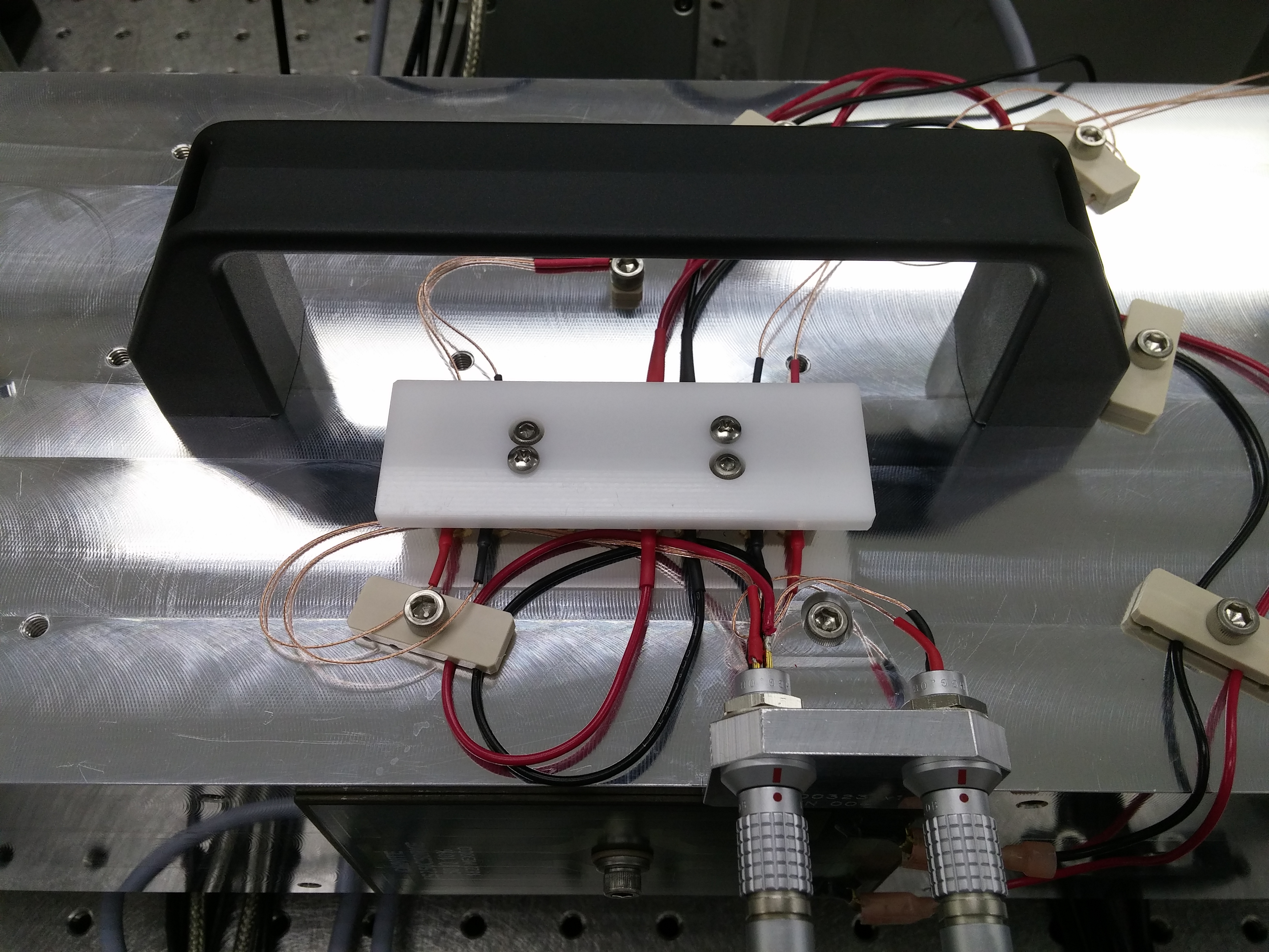
Nothing terribly alarming there, so we moved down the beam path towards the RefCav. At the EOM (provides the 21.5MHz sidebands for PDH locking the RefCav) we noticed that what was one beam at the input became two at the output, which is definitely a problem. Looking at the output aperture of the EOM it was obviously clipping, so a realignment was necessary. Also, we noticed that the EOM pedestal was tilted at a rather extreme angle, and that the EOM mount was using almost all of its horizontal adjustment range to compensate for this tilt. Before changing anything, we re-centered 2 irises for alignment recovery: the iris right in front of the RefCav (Input Periscope Iris, or IPI), and the iris in the RFPD path. We then began the realignment by straightening the EOM pedestal, then backing out the horizontal adjustment screws so we actually had some adjustment range. We then aligned the EOM itself. To do this, we removed the EOM and replaced it with an empty EOM base (1st picture); this allowed us to see the inside of the EOM housing and get a really accurate alignment to the input and output apertures. We carefully replaced the EOM and checked the alignment, which looked good. We then looked for our second beam and, lo and behold, the 2nd beam was gone (yay!). Alas, this change in EOM alignment also changed our beam alignment to the RefCav (awww...). To recover this we used mirror M27 to center the beam on the IPI, and used the top periscope mirror to center the beam on the RFPD iris. This was sufficient for the FSS to relock, and it had a TPD = 3.4V. Tweaking this with the picomotor brought the TPD up to ~4.3V, but couldn't get any higher than that.
Thinking we we falling off of the RFPD, Rick used an IR viewer to take a look. Sure enough, we were falling off of the top of the RFPD. So we unlocked the FSS and re-centered the beam on the RFPD. Before re-centering the RFPD DC was reading ~0.12V, after it was reading ~0.61V, so a 5x increase. Upon relocking the FSS the RefCav TPD was reading ~4.5V without us doing anything. Tweaking the alignment with the picos brought the TPD up to ~4.7V. Since we had to re-center the RFPD, we checked the centering of the TPD as well and noticed that there was almost no "flat spot" when moving the beam over the TPD. We looked at the beam with a card and noticed it was fairly large and was not focusing down onto the TPD, despite passing through a lens. Well, upon removing the lens to check its focal length we found out why: it was a 200mm lens, and with only roughly 4" between the turning mirror and the TPD, of course it wasn't focussing the beam. We swapped this out for a 50mm focal length lens and centered the beam on the TPD. The TPD now read 5.0V, which is where we left it. Before launching on TF measurements to set the loop gains, we did a couple of other quick things:
- We increased the ND filter on the RefCav Refl camera; we took out the OD = 1.0 ND filter and replaced it with a 3mm thick piece of NG3 glass.
- This lowered the intensity of the reflected spot so we could better see it.
- We physically moved the FSS cameras so the beams were better centered.
- We installed a cover on the PMC electrical terminal, see 2nd picture.
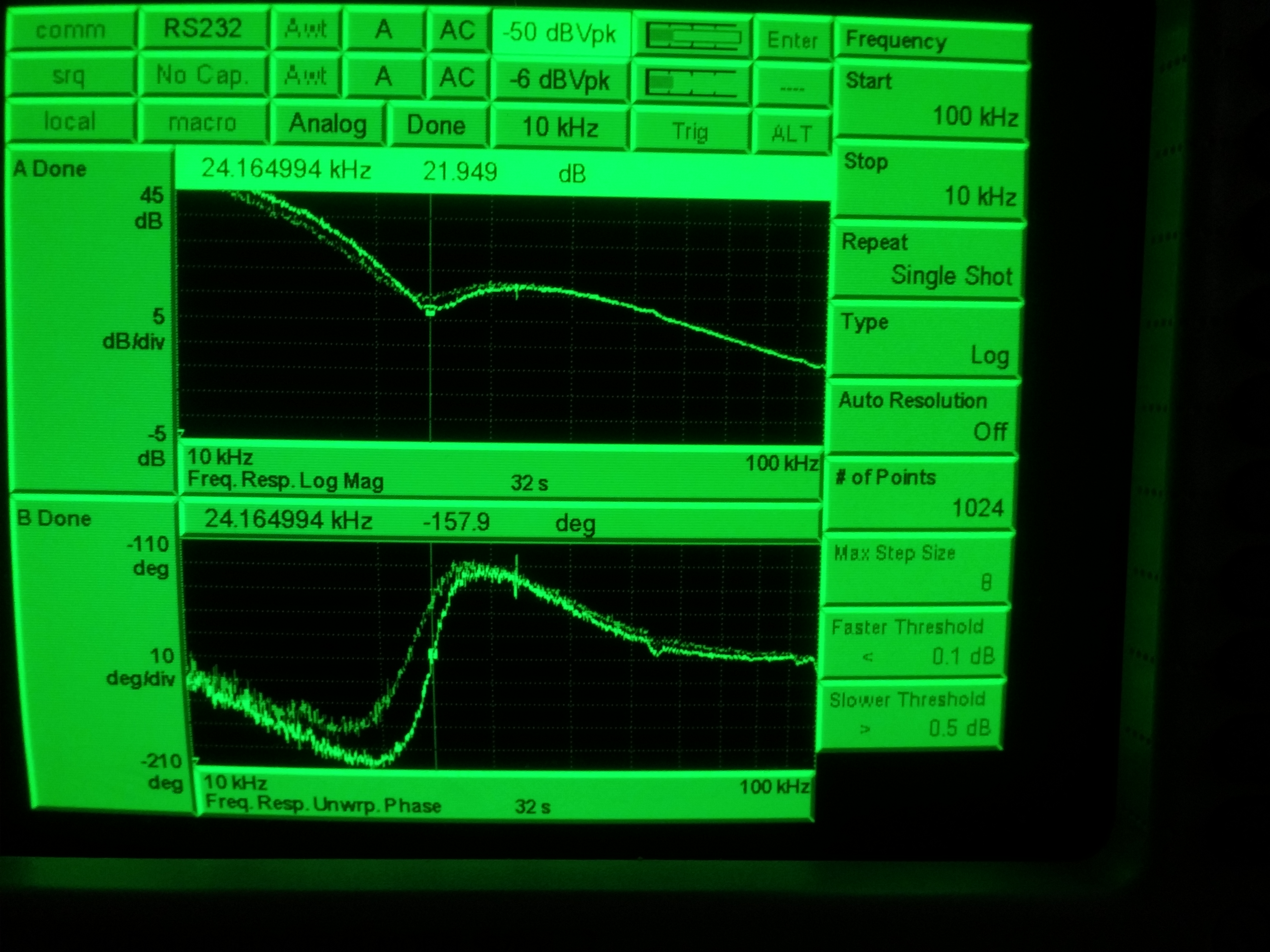
Moving on to setting the loop gains, we started with measuring the crossover (which is at ~20kHz). We settled on a Fast gain of 16, see 3rd picture (the more faint reference trace is with the Fast gain at 14; we unwrapped the phase for the lower plot so we could see what it was doing). There was no evidence of the loop oscillating or really having any problems at all with this gain setting (we're well above the UGF here); in fact, the EOM voltage was much lower at this gain setting, indicating we weren't driving it as hard to keep the loop locked (this puts most of the burden on the NPRO PZT, which showed no signs of having problems), so we kept this value. If there's evidence of the "breathing" Keita logged here, this setting can be changed, but we found no evidence of issues on the PSL side of things. We then measured the OLTF for the FSS, see 4th attachment. This is with a common gain of 20 and a fast gain of 16; at these gain settings the UGF of the FSS is 465kHz, so we made no changes. At this point we were at the end of the maintenance window, so we cleaned up and left the enclosure. Before leaving, I reset both PSL power watchdogs (20:05 UTC, 12:05 PST) to complete FAMIS 10735.
I should note that as we were leaving the enclosure we did notice that the FSS took a while to lock for the final time. As the only gain we changed was the Fast gain, I dropped it to about 12 and things seemed like it would lock, but it continued to have some issue. I turned off the autolocker and immediately turned it back on, and the FSS locked right up without a problem. I returned the Fast gain to 16 and the loop had zero issues with the change, just hummed right along. Not sure what caused this, but simply turning the FSS autolocker off then immediately on again had it locked.
Back in the control room, the RefCav TPD was reading ~4.7V, so there was some change between our last adjustment and us leaving the enclosure (and subsequently turning off the environmental controls). I'll monitor this to see if it continues to change or if it stabilizes; I expect it to stabilize as the temperature in the enclosure stabilizes after our incursion. After we left, both temperature sensors were reading 70 °F; the temp generally hangs out around 73 °F, so I'm expecting some drift as the enclosure temp returns to normal. I can tweak this, if necessary, at the next available opportunity (earthquake, next maintenance window, etc.).