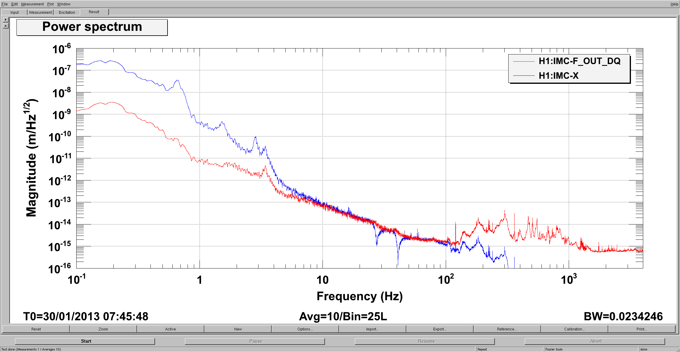
Attached is a plot of the calibrated IMC control signals for the following relevant control loop settings:
- Common Mode Board: common gain = 20 db, compensation and 1st common boost on, fast gain = -2 db.
- MC2_M3_LOCK_L filters: gain -1000, FM5 (150:4) and FM8 (CLP100) enabled, limt to 400k.
- MC2_M2_LOCK_L filters: gain = 0.03, FM1 (0.01:0.1), FM2 (0.03:1), FM3 (Stab8:2), FM4 (300:1) and FM10 (ELF80) enabled, limit to 300k.
The signals have been calibrated following L1 example. Details on the calibration follow (both for clarity and to check that I correctly interpreted what they has been done at L1).
---- IMC_F ----
- The fast path control signal is directly acquired from the Common Mode Board and becomes the input to the H1IMC-F filter bank (H1:IMC_F_INMON)
- the filter bank contains the following (enabled) filters:
- "cts2V" that converts ADC counts in volts (0.000610016 V/ct)
- "InvGenFilt" that compensates for the withening filter at the output of the Common Mode Board (double pole at 10 Hz, double zero at 100 Hz, DC gain = 0.5)
- "VCO" that accounts for the VCO DC gain (365714 Hz/V, obtained from the test report of unit D0900605-S1200558 and multiplied by 2 to account for the AOM double pass) and filter (pole at 1.6 Hz, zero at 40 Hz)
- "FtoL" (I added this at H1) that converts the frequency variations dF into equivalent modecleaner round-trip variations dL using dL = dF * L * lambda / c, where L is the length of the IMC (16.47 m nominal), lambda = 1064e-9 m, c=3*10^8 m/s.
---- IMC_X ----
- the output of the MC2_[M3/M2]_LOCK_L filters are input in the IMC-X_[M2/M3] filters bank, respectively
- the MC3 filter bank contains the following enabled filters:
- "dc_cal" that converts the length actuation into mass displacement at DC
- "sus_d" that accounts for the TF from force on M3 to displacement of M3 (rescaled for 0 dB DC gain because of the existence of "dc_cal"). Note that this TF has been calculated for L1 in the case of velocity damping; although we are still using velocity damping here at H1, it need to be verified that we are using the same setting that L1 was using when the TF was calculated.
- "white", a whitening filter (two 0.2 Hz poles and two 1000 Hz zeros) used to get rid of digitization noise. It need to be tken into account when analyzing data.
- the MC2 filter bank contains similar filters, except that "sus_d" is replaced by the combination of "sus_d1" an "sus_d2", that account for the TF from force on M2 to displacement of M3.
- the outputs of both filter banks are summed to estimate the actual M3 motion.
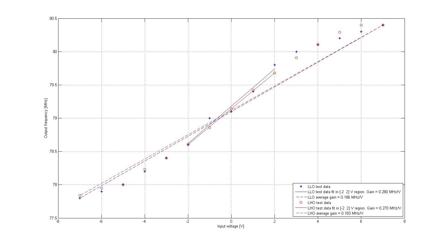
There has been a bit of discussion about the value of the VCO gain used here, as it seemd to be different enough from the one used a LLO (as much as peple suspected the double pass had been ignored, thus missing a factor 2).
After a bit of back and forth by e-mail, Anamaria spotted the problem: in obtaining this facor from the testing documentation I had very naively assumed a linear response over the tested range, thus calculating the gain as [range of output frequency] / [range of input voltage].
Plotting the data points reported in the abovementioned documentation for the units in use at LHO (S1200558) and LLO (S1200580) reveals instead that the two units behave very similarly, but not linearly. The gain in the linear region around 0 V is ~ 0.27 MHz/V, versus the ~0.18 MHz/V calculated over the entire range (see attached plot). The gain can be as low as 100 kHz/V in the region around 5V (or -5V).