A lot has happened since my last alog on this topic.
I presented a little presentation to the Pcal team some weeks ago, where I claimed I was able to remove all observable temperature dependence in the the Pcal Calibration tools. Unfortunately this result is valid only for the "old" style detectors, which feature a board that only has a photodiode and no other on-board electronics.
Since the WSL as been returned here, and is effectively a spare until a replacement is put together, I have been using it to investigate temperature dependence of the in-use-boards, which have a number of extra circuitry components that get really quite hot when these things are being used... Just turning on the instruments heats up the circuit board by 6.5 degC!
I will summarise contributions to observed temperature dependence as I currently know it, in order of importance (in units of HOPs/degC = hundredths of a percent/degC):
- Geometric hole expansion discussed in presentation
- ~3-4 HOPs/degC, dependant on individual sphere
- Rick Savage is working on a design to restrict the PD FOV to not be sensitive to this (at the cost of total observed power)
- ~3-4 HOPs/degC, dependant on individual sphere
- Cross coupling of voltage from the temperature sensor to the output.
- V_out_extra ~= 1.4 * 10^-3 V_temp . This is negligible in normal use.
- But if FOV is restricted and incident power is 20x less, then this constitutes 1 HOP/degC
- Unknown circuit board dependence (not PD or main resistor resistivity change)
- Seen as what is needed to explain all remaining responsivity not mentioned in the other categories:
- 2.8 * 10^-5 V / degC (at nominal voltage of 3V) - not currently sure if it depends on voltage seen - will investigate this next.
- ~= 0.84 HOPs/degC
- This same dependance was seen on multiple boards of the same version of the circuit boards used in all the standards.
- In case you are wondering: no, I didn't produce this factor just to make the plot below have zero temp. dependence.
- I extracted this relationship from an older experiment in the presentation which I re-examined with renewed confidence in the temperature sensors (the experiment with a set current source into a board that has no PD)
- Resistance change in resistor that converts current from PD to Voltage
- 0.1 HOPs/degC
- PD Dark current
- ~0.01 HOPs/degC
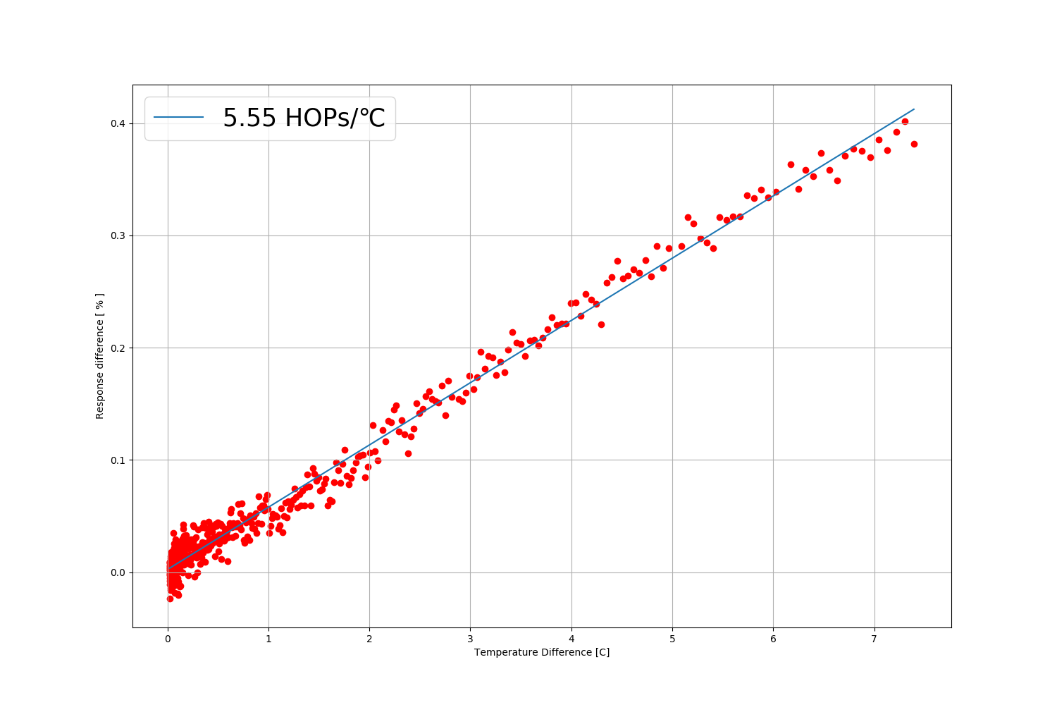
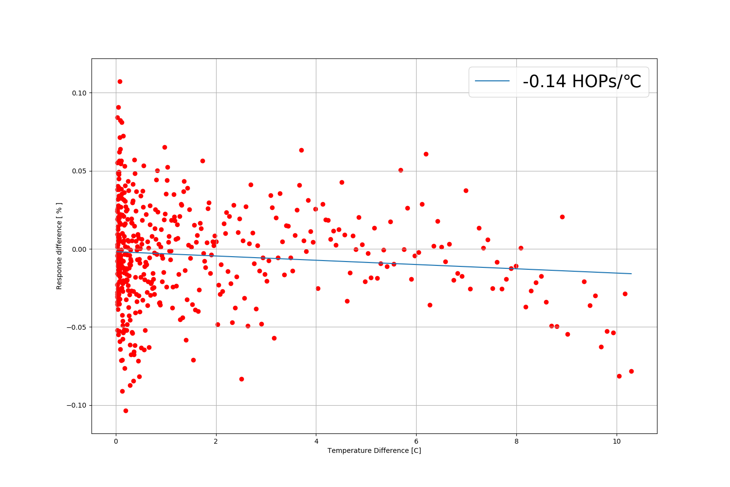
Putting all of these aspects together, both experimentally (with reduced FOV) and numerically (subtracting known temperature dependent factors), I managed to reduce observed temperature dependence in the WSL from ~5.5 HOPs/degC (Resp_vs_Temp_Intial.png) to -0.14 HOPs/degC (Resp_vs_Temp_Final.png). There is a small change left over that goes the opposite way. I suspect this is an effective increase in responsivity due to the height dimension of the hole changing (see the presentation for an illustration).
Having spoken with Niko,
One component we have not considered yet is the transimpedance amplifier: We previously ignored it as it should contribute nothing to the output at DC voltages.
There are some questionable things in it's spec sheet.
I'll investigate this by trying to heat it only in isolation.
I did a pseudo-experiment before leaving today.
I attached the test board with no PD to a clamp, and gave it a current source. With a dissasembled pen I would blow on components to cool them, to see what gives me considerable drops in output voltage.
When cooling the capasitor that is in parallell with the main transimpedance feedback resistor, I got the largest voltage change - the transimpedance amplifer itself gave no real change despite my attempts to cool it.
I have a very strong hunch that this is the "unknown temperature dependance" that I am looking for. I will investigate this more scientifically in the near future.
I got hold of a soldering iron that goes down to 65 degC from Mark.
Checked the output voltage effect from heainting individual components - The R2 resistor is the biggest contributor on the entire board that I can find, and gives <0.1 HOPS/degC (~0.02) (this is a better resistor than the ones in the working standards).
The C5 capasior in parallel gieves about 1/3 of the response change when heated, compared to the resistor.
The transimpedance amplifier, and buffer out amplifier do not appear to constitute ant changes, nor does any other component (I tested them all).
I tried heating the whole board in the oven, and found changes consistent with just the R2 resistor (maybe a little bit more). While the board was cooling, I found that cooling the Transimpedance amplifier by blowing on it lenth-wise had the biggest effect on the output. I can't apply heat to it in that way and may be why I missed in on the first try. The offset voltage (or current) drift at inpout and output per deg/C is largely consistant with what I am seeing.
I've run into a bit of a brick wall in quantifying contributions however (could explain the Transimpedance Amplifier acting up). I noticed voltage fluctations on the scale of the effects I am studying apparently coming and going for now reason. While unplugging my setup I noticed that the earthing of my current source *is* coupling to my output, to the tune of the effects that I am studying. Basically the optics lab appear to be riddled with ground loops - and probably needs an overhaul of grounding.