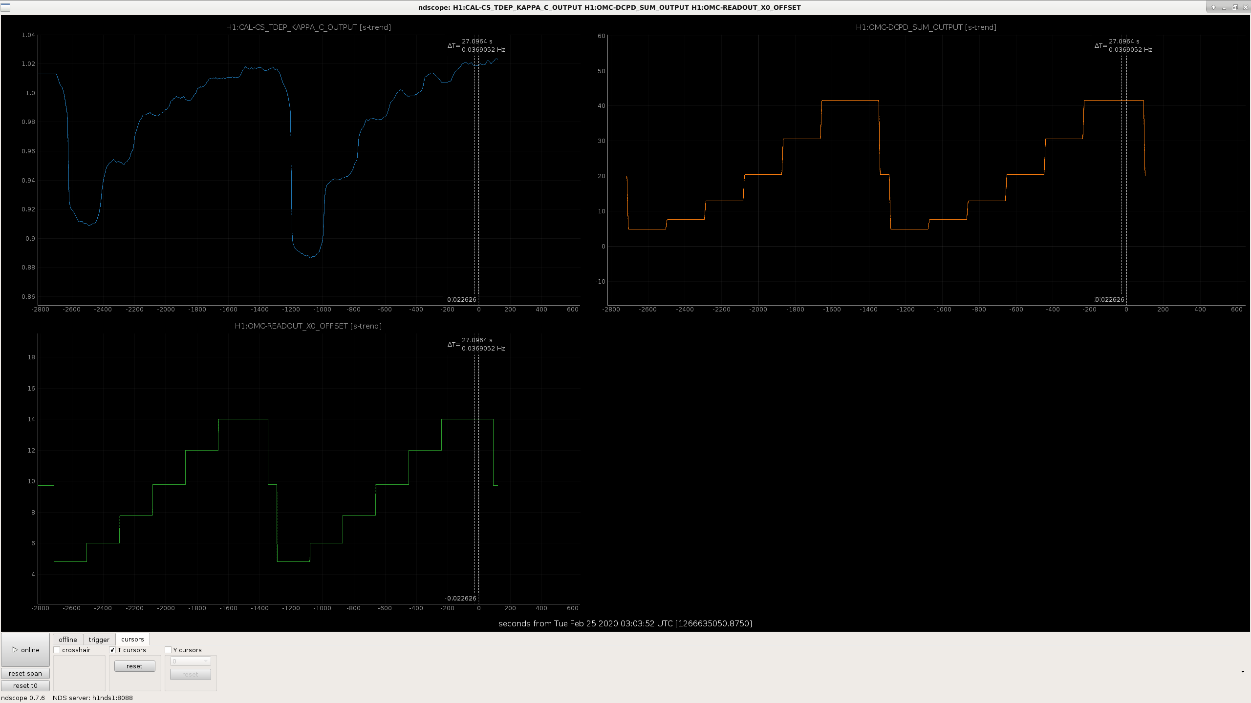
I measured the optical gain for different light levels on the DCPDs before and after lowering the 9MHz modulation depth. We did this as we relocked.
The scan started at 2:18:40 UTC Feb 23rd, and went until 3:05:23 UTC
Attached is a plot of the DCPD power vs optical gain during this test. Although these two traces look similar when plotted this way, there is a consistent difference between the two, and fitting for the amount of junk light inboth cases gives 1.09 +/- 0.06 mA in the high modulation depth measurement, and 1.35+/- 0.06 mA in the low modulation depth case.
While looking at this data I realized that I had made an error in an earlier alog about modulation depths, which is corrected in the comment now. Based on the change in modulation depth (first scan taken with a 23.4dBm epics setting on driver, which means 0.189 radians modulation depth, second scan taken at 20.3dBm setting which means 0.159 radians), we would expect that carrier light in the interferometer would be reduced by 0.5% and the sideband power injected would be increased by 40% when the modulation depth is decreased.
This result suggests that the junk light we are seeing is probably not the 9th order 9MHz mode which is near resonance in H1's OMC 46667.
One explanation for this result could be that I made the test while the interferometer was still thermalizing. The attached screenshot shows trends while the measurement was taken, the fastest part of the thermal transient was over.
There was a 0.8% increase in the circulating power in the Y arm, 0.9% increase in the X arm, when the modulation depth was increased, so both of those are sligthly higher than we expected for the change in modulation depth. It could be that an alignment set point changes when we change the 9MHz modulation depth, which is generating extra carrier junk light.


The increase in junk light after the 9MHz reduction made Keita and I ask ourselves why we are doing this reduction, and if the tests that motivated the change would have the same outcome in our current configuration. It seems plausible that the reason this produces junk light (if it does) are related to TCS settings, spot positions and circulating power.
history of 9MHz modulation depth:
- Sept 2016:
- 9MHz reduction by 6dB added to guardian after power increase. 29983
- OMC trans image changed with 6dB reduction in 9MHz; suggestion that 900 Hz peak is reduced by 9MHz reduction, 29817 I seem to remember that this change in the 900Hz peak was not repeatable, we were just being confused by noise which came and went.
- Identification of 9th order 9MHz mode in transmission through OMC: 29395
- Nov 2016:
- 9MHz reduction which was done after power increase is removed from guardian because of locklosses, we weren't sure if it mattered for sensitivity.
- April 2018:
- EOM swapped, so dBm settings are not directly comparable before and after this time. 41435
- late Oct 2018:
- Refl 9 slew rate limited: 44771
- The first result in this alog looks dramatic but if you read all the comments and the story becomes much less clear. The drive levels being compared aren't written in the alog, but I am infering from the plots that these are comparisons between 23dBm drive setting (nominal at the time, 0.184rad) and 17dBm (called redcued here, 0.130 radians) : 44781
- Nov 2018:
- increasing 9MHz by 6dB compared to nominal setting (of 20dBm) makes DARM worse, lowering it doesn't help 45173
- I am not finding this discussion in the alog, but my memory is that Koji told us that the EOM driver is more noisy when operating at it's max power, so we probably have more 9MHz RIN when we operate at 26dBm on the driver.
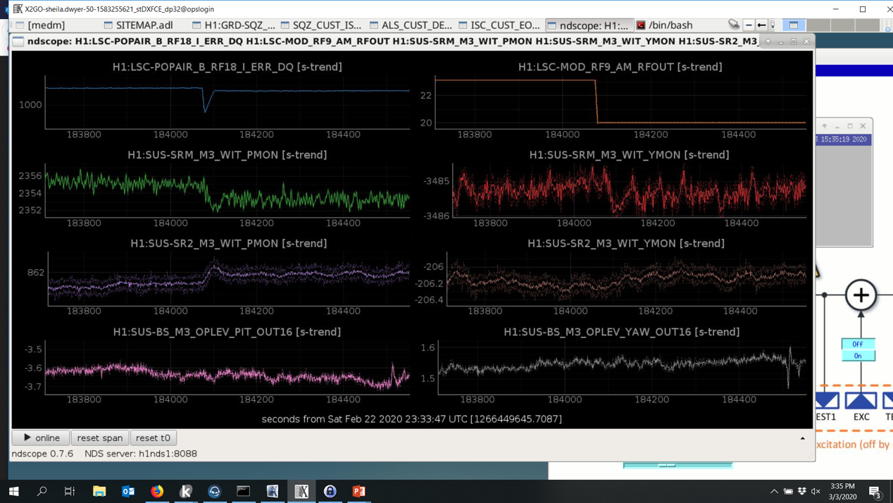
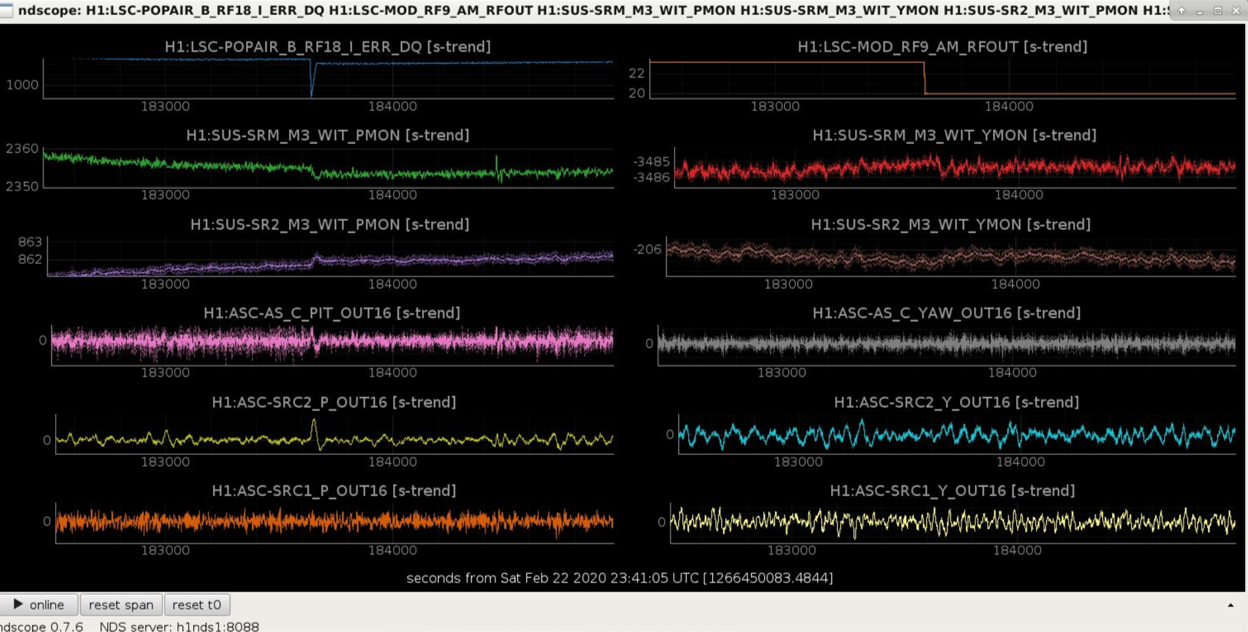
Daniel suggested that we look at what happens to the BS alignment when the modulation depth changes, since AS36 is the signal used to control the BS alignment. Jenne looked into this and found that the beam splitter doesn't react to the change in modulation depth, but SR2 and SRM both do. The first attachment shows that this is mostly in pitch, but there is also a yaw reaction. The second attachment shows that the AS-C QPD seems to be the reason why changing this modulation depth changes the alignment of the SRC. (You can see the change in AS_C before the SRC2 loop brings it back to it's error point by moving the alignment of SR2+SRM). There is not much happening in the AS72 loop (SRC1), which you would expect if they are well diagonalized.
This suggests that the amount of junk light we have on the DCPDs can be changed by changing our offset on AS_C. We plan to try a test of this tomorow.