On Tuesday I measured the dark noise of the OMC DCPDs in various analog electronics configurations, to help understand what our options might be for running in a different configuration that would allow us to use a higher DARM offset.
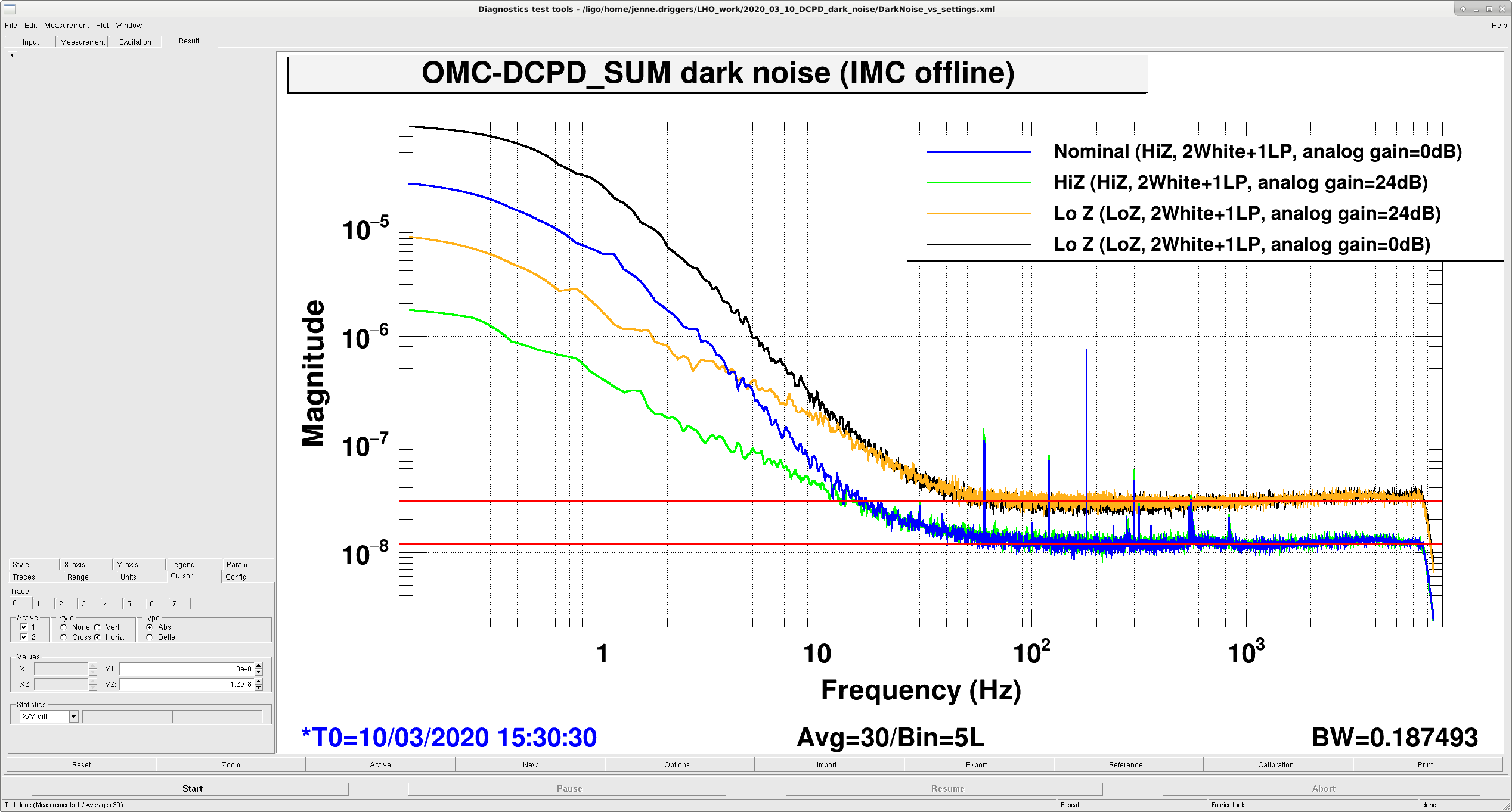
In the attached screenshot I have the dark noise of 4 different configurations, high and low transimpedance and high and low analog whitening gain. Although unlabeled, the yaxis is in mA/rtHz. These are at OMC DCPD SUM, so have digital compensation for the analog changes: the High Z filter module is off for the Low Z measurements, and the digital gain is reduced by 24dB for the measurements with increased analog gain. The increase in analog gain has an impact in the region where we are limited by the ADC noise, below 12 Hz or so. Above about 12 Hz, the dark noise increases by a factor of 2.5 when we reduce the transimpedance by a factor of 4.
The noise limit at higher frequencies for the LowZ case is well explained by noise from the DCPD itself, which Rich Abbott has quoted to me as 300 nV/rtHz at 100 Hz over the low Z 100 Ohm resistor coming into the whitening chassis. This translates to 3.02e-8 mA / rtHz and matches my spectrum at 100 Hz. If I assume that the 300nV/rtHz over the 100 Ohm resistor is a current noise, then that gives me 3 nA/rtHz. Assuming that that current noise is constant then over the higher impedance 400 Ohm resistor I should have 1200 nV/rtHz coming into the whitening chassis. But, that would result in 2.15e-8 mA/rtHz at 100 Hz, which is higher than what I measure. So, I think I need to check with Rich to see if the DCPD noise is different somehow over the higher impedance.
Anyhow, Rich and PeterF have looked at some noise simulations, and it seems like we can reduce the analog whitening gain by a factor of 2 and leave the DCPDs with the higher transimipedance, so we'll likely pursue that avenue.
In the attached .xml file, I have the several references saved, in case they are ever helpful to come back to. For each case, I have the OMC DCPD sum, as well as the IN1 channel of each PD.
- Refs 0, 1, 2: Nominal configuration. 0dB analog gain & digital gain = 1000, analog HighZ & HighZ filter module on, 2 whitening filters and 1 lowpass in analog & compensating digital filters.
- Refs 3, 4, 5: Same as set #1, but increased analog gain. +24dB analog gain & digital gain = 63.096 (-24dB from 1000), analog HighZ & HighZ filter module on, 2 whitening filters and 1 lowpass in analog & compensating digital filters.
- Refs 6, 7, 8: Same as set #1, but removed 1 whitening filter. 0dB analog gain & digital gain = 1000, analog HighZ & HighZ filter module on, 1 whitening filter and 1 lowpass in analog & compensating digital filters.
- Refs 9, 10, 11: Same as case #3, but also removed lowpass. 0dB analog gain & digital gain = 1000, analog HighZ & HighZ filter module on, 1 whitening filter in analog & compensating digital filter.
- Refs 12, 13, 14: Same as case #4, but increased analog gain. +24dB analog gain & digital gain = 63.096, analog HighZ & HighZ filter module on, 1 whitening filter in analog & compensating digital filter.
- Refs 15, 16, 17: Same as case #2, but with LowZ. +24dB analog gain & digital gain = 63.096 (-24dB from 1000), analog LowZ & HighZ filter module off, 2 whitening filters and 1 lowpass in analog & compensating digital filters.
- Refs 18, 19, 20: Same as case #6, but with lowered analog gain. 0dB analog gain & digital gain = 1000, analog LowZ & HighZ filter module off, 2 whitening filters and 1 lowpass in analog & compensating digital filters.

I could not understand "3.02 mA/rtHz" and "2.15 mA/rtHz". Is there a unit issue? -> The main entry was corrected
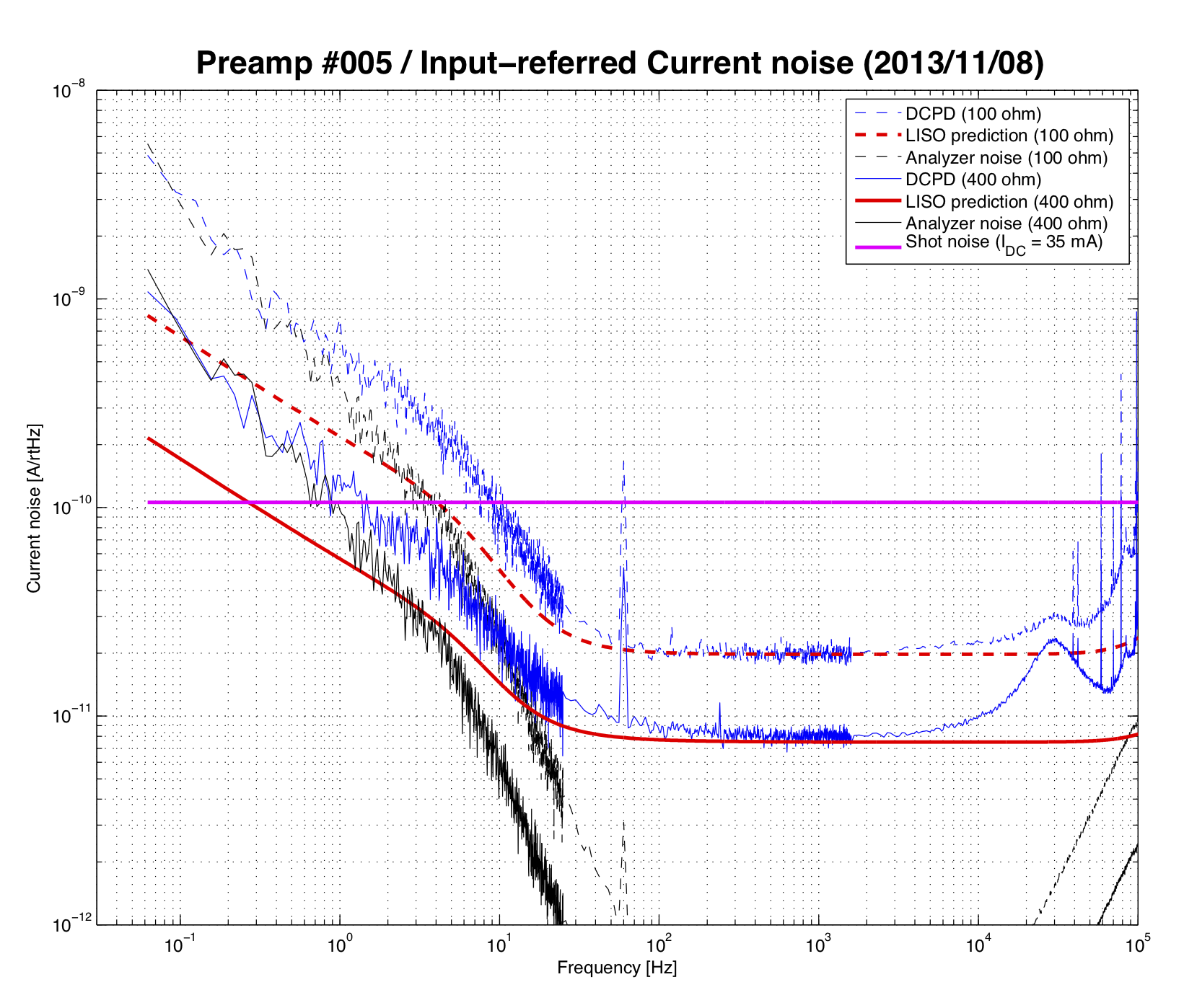
Your measurement matches with the measured noise of the DCPD preamps:
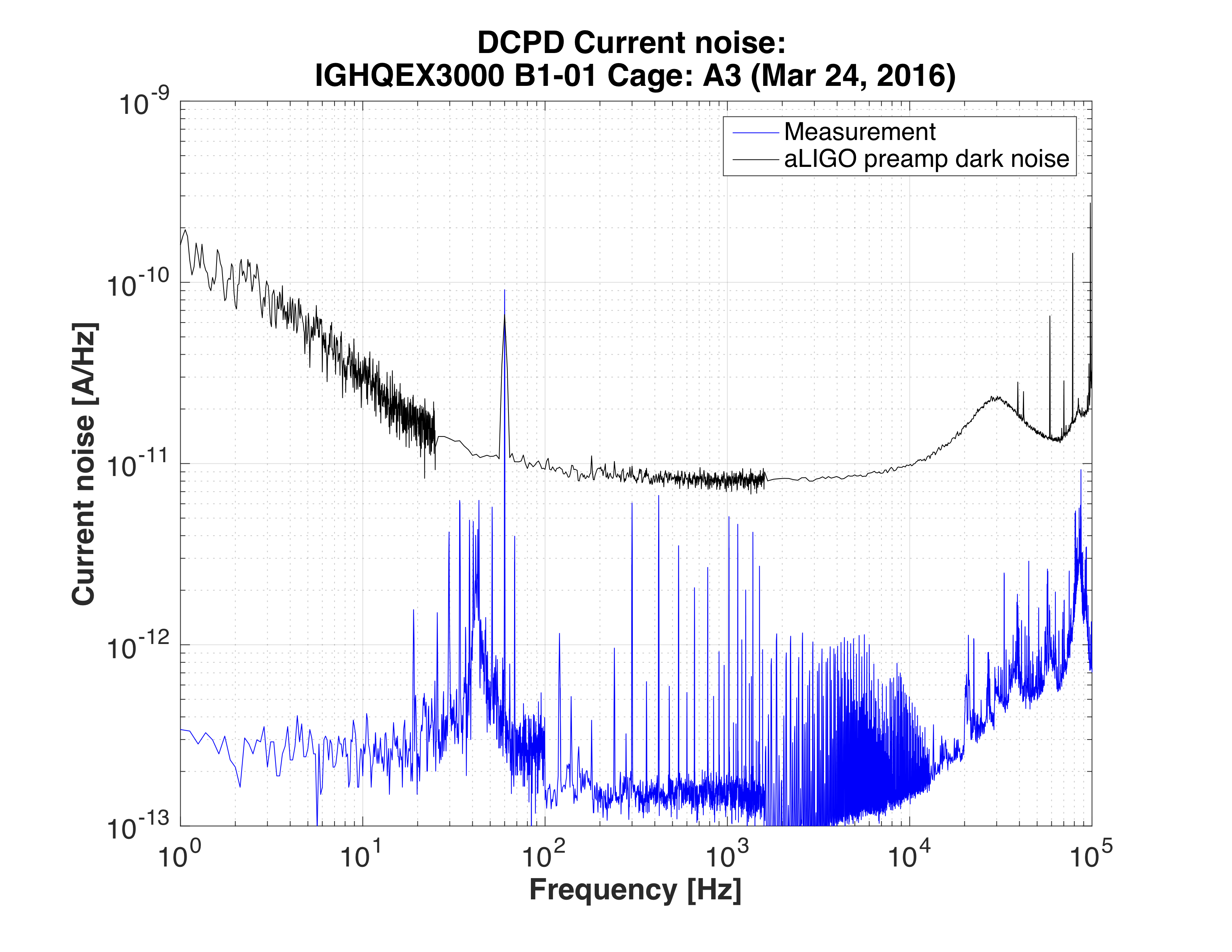
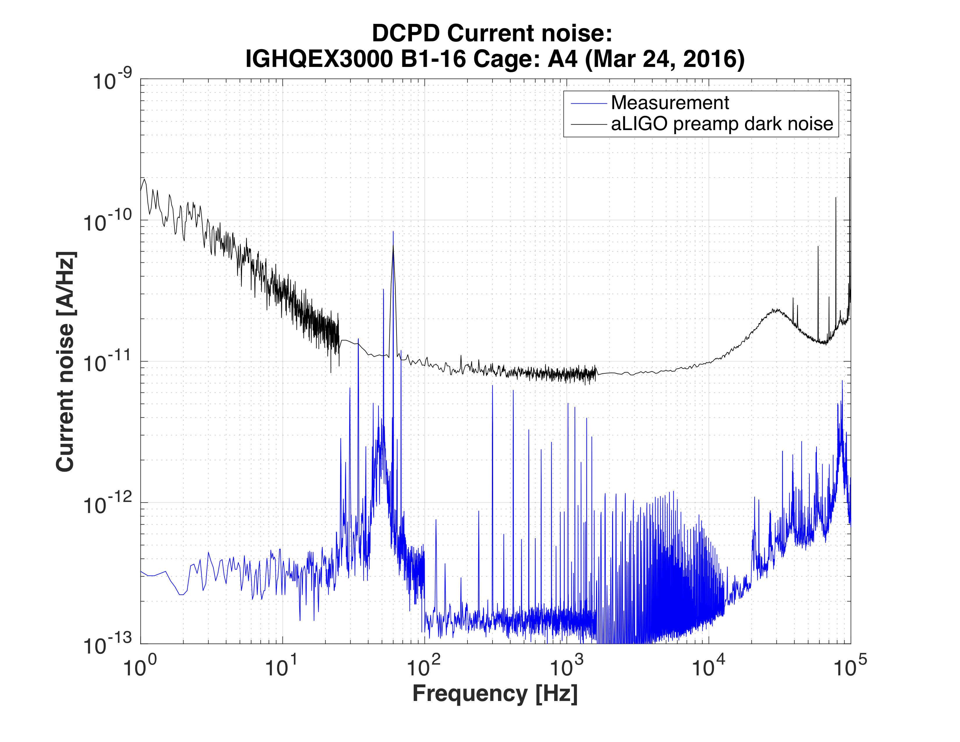
- These photodiodes were tested at Caltech and indicated low current noise (<0.2pA/rtHz). See Attachments 1&2 blue curves. i.e. The dark noise is supposed to be dominated by the preamp noise.
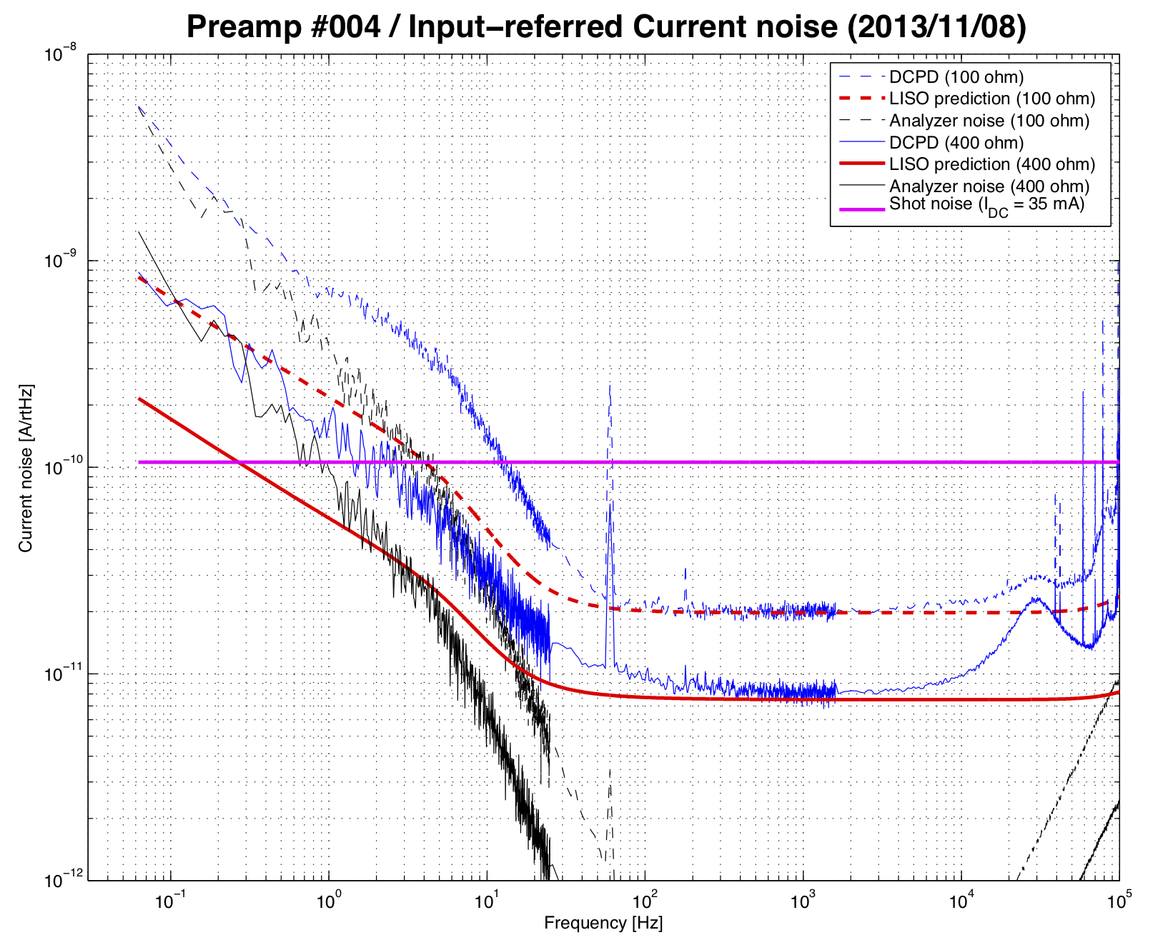
- The DCPD preamps (D060572) were tested and documented as T1300552. There, the input equivalent current noise of the DCPD amp was measured to be 20pA/rtHz and 8pA/rtHz for Z=100Ohm and 400Ohm, respectively. (See Attachments 3&4 for the excerpt from the document). The noise level is determined by the combination of the current noise of Z and the noise of the preamp circuit. As you are adding the noise of two preamps, the total noise is sqrt(2) higher, i.e. 11pA/rtHz and 28pA/rtHz for Z=100Ohm and 400Ohm, respectively. These numbers match with your measurement.
Okay, thanks Koji for clarifying. Also, those numbers should have been 2-3 * 10^(-8) mA/rtHz. I forgot to include the 1e-8 part :/
(this comment is obsolete now)