jeffrey.kissel@LIGO.ORG - posted 16:18, Thursday 03 September 2020 - last comment - 11:27, Monday 13 September 2021(56683)
Successful Swan Song of H1 NCAL Prototype v1
L. Datrier, C. Gray, J. Kissel, R. Kumar, T. Mistry, M. Ross
We have successfully driven the H1 NCAL Prototype -v1 in to H1 while in nominal low noise one last time, in order to close out the data collection for the existing system before we re-measure its physical position and remove it for upgrades.
With NCAL rotation frequencies at 4 points between 11 and 16 Hz NCAL, we created gravitational force at twice ("2f"; created by the quadrupole mass arrangement) and thrice ("3f", created by the hexapole arrangement), and did so with PCALY also forcing the test mass with photon radiation pressure force at frequencies 0.1 Hz away from each 2f and 3f frequencies.
With this measurement, unlike the results presented from Dec 04 2019 (see G2000352), we intend to improve our methods and compare NCAL against PCAL, with high signal-to-noise ratio.
In order to account for frequency-dependent changes in the detector's response to these (frequency independent) PCAL and NCAL forces, we also gathered data with the forcing frequencies swapped (e.g. both with PCAL at [NCAL 2f + 0.1 Hz] and with NCAL at 2f' = 2f+0.1 Hz, PCAL at [NCAL 2f' - 0.1 Hz], and similarly for 3f.).
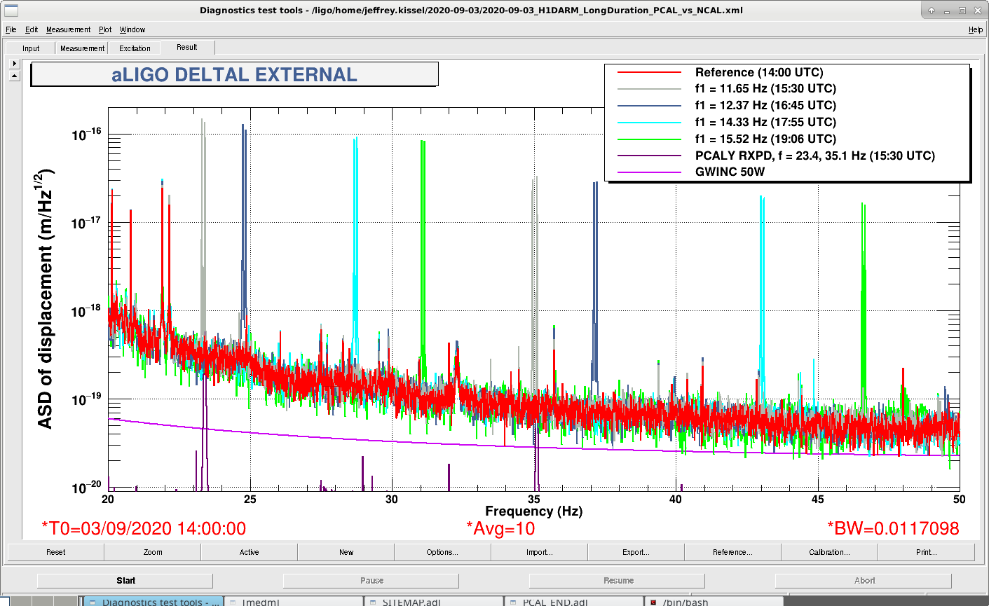
The complete data analysis is to come, but for now, I attach a pretty plot to prove that the injections happened: an amplitude spectral density of DELTAL_EXTERNAL in the presence of
(red) no extra force injections beyond the normal that are present in nominal low noise (e.g. as shown, you can see the upper few alignment dither system lines).
(gray) NCAL spinning at 1f = 11.6845 Hz, driving 2f = 23.2969 Hz and 3f = 34.9453 Hz, and PCAL at 23.4 and 35.1 Hz
(navy) NCAL spinning at 1f = 12.3711 Hz, driving 2f = 24.7422 Hz and 3f = 37.1094 Hz, and PCAL at 24.84 and 37.21 Hz
(cyan) NCAL spinning at 1f = 14.3321 Hz, driving 2f = 28.6641 Hz and 3f = 42.9922 Hz, and PCAL at 28.76 and 43.09 Hz
(green) NCAL spinning at 1f = 15.5200 Hz, driving 2f = 31.0391 Hz and 3f = 46.5625 Hz, and PCAL at 31.14 and 46.66 Hz
(Data with the frequencies swapped are not shown, since this "for-demonstration-purposes-only" plot is already busy enough, and DTT is limited to 8 traces per plot.)
More details to come in the comments below.
A resounding success!
Obligatory reminders:
- Any NCAL system is not intended to, nor will it ever *replace* the PCAL system. The PCAL system is just far too versatile, and safely drive arbitrary wave-forms out to frequencies well past several kHz with adjustable amplitude.
- Any NCAL system will *never* be run while the detector is observing for gravitational waves.
- This prototype NCAL system's systematic error budget will land no-where-near competitive to the current PCAL system, which for this particular H1 PCALY RX PD we've used today comes in at remarkable culmination of decades of work with an estimated systematic error of channel value * (1 - 0.00139) and absolute uncertainty of (channel value) +/- 0.41% (1 sigma confidence interval).
- In short, this system is/was a prototype of a future, promising supplementary absolute (force or displacement) reference for the detector.
- While some LSC institutions will likely continue development, the LIGO lab has no immediate plans to support a next generation NCAL system to supplement the PCAL system without identifying additional funding, person-power, and need.
Images attached to this report
Comments related to this report
For future data collection and processing

The above attached demonstrative ASDs were made with 0.01 Hz binwidth, with 10 averages at 75% FFT overlap.

While we intend to process the *ratio* of these injected forces, such that any systematic error and uncertainty in the calibration of the detector is canceled out, I still note a few known systematic errors in the current h(t) data (calibrated with the O3B model parameters from modelparams_H1_20200103.py):
(1) The DARM2 bank, FM6 -- a violin mode notch -- was turned off during the entirety of this measurement. While on the surface this doesn't impact estimates of h(t), alas, we've learned this lesson before, that this filter changes the response function, which changes calibration line amplitudes, which creates error in the estimate of time-dependent correction factors, which -- since they're still applied -- errantly correct the data for time-dependent factors that haven't actually changed.

(2) The OMC DPCD's whitening are in the configuration where only the 1st stage of whitening is used, as opposed to all 3 stages. That means the systematic error described in PART II of G2000527 is still present.

(3) The ETMX ESD cable connection between the LV ESD driver remains free of the current limiting resistors that were in place up until Feb 11 2020. That changed the frequency-dependent actuation strength of the TST stage from the model, which impacts the response function in the bucket as discussed in LHO aLOGs 55041 and 56351.

(4) The IFO had been happily running in nominal low noise all night prior to us joining it's party at ~16:00 UTC (08:00 PDT), so the IFO's response function was well-thermalized and stable throughout this test (~15:00 - 20:00 UTC), confirmed by reported TDCFs (see 20200903 Summary Page).

Finally, in order to confirm the expected level of systematic error in h(t), I gathered a long, 5 minute, broad-band injection with PCAL for future analysis, that lives here:
    /ligo/svncommon/CalSVN/aligocalibration/trunk/Runs/O3/H1/Measurements/FullIFOSensingTFs/
        2020-09-03_H1_PCALY2DARMTF_BB_3min.xml

I'm not sure from where it came (likely, J. Kissel's off-the-cuff memory, or typo), but the reported calibration for the NCAL motor drive frequency request (H1:CAL-NCALX_MOVE_VELOCITY_VELOCITY_REQ) has been incorrect (was 104.3 ct/Hz). Timesh correctly reports that the motor drive frequency calibration is
    2^20 / 1e4 = 104.8576 ct / Hz

This *correct* motor drive frequency request calibration was employed in this measurement, and confirmed with measurement of 2f and 3f frequencies in DELTAL_EXTERNAL with 0.01 Hz binwidth resolution.

Now, on to details about the injections.
 - All times are UTC, and on UTC date 2020-Sep-03.
 - All times below report durations of stable time *after* NCAL and PCAL systems have been settled in the reported frequency for several minutes.
 - There are occasional, rather large glitches, smattered every once-in-a-while in the data. As far as we can tell, these were unrelated to our force injections, happening well after our force instruments were settled and stabling injecting at requested frequencies. We should investigate the use of some de-glitching algorithms in order to maximize the use of the data we have.
 - NCAL 2f and 3f frequencies were *measured* using a 0.01 Hz frequency resolution ASD of DELTAL_EXTERNAL, while 1f frequencies were requested reported using the requested counts of motor drive * the ct/Hz calibration above. PCAL frequencies are reported as what was requested (though also confirmed with measurement).
 - Parenthetical notes are after each test time duration. "n" refers to NCAL and "p" refers to PCAL. "lo" indicates that the NCAL or PCAL was forcing at the lower frequency of the two pairs at each 2f or 3f for that duration, and "hi" indicates the respective forcer was forcing the higher frequency for that duration.

Time (Start - Stop UTC)        NCAL 1f (ct)   NCAL 1f (Hz)    NCAL 2f (Hz)   NCAL 3f (Hz)   PCAL 2f (Hz)   PCAL 3f (Hz)
14:00 - 15:00 (reference)        none          none            none           none            none           none

15:10 - 15:20 (ncal alone)     1221.353        11.6477         23.2969        34.9453          none           none

15:30 - 16:00 (n lo, p hi)     1221.353        11.6477         23.2969        34.9453         23.4           35.1
16:05 - 16:35 (n hi, p lo)     1226.834        11.7000         23.3984        35.1016         23.2969        34.9453

16:45 - 17:15 (n lo, p hi)     1297.089        12.3700         24.7422        34.1094         24.84          37.21
17:20 - 17:50 (n hi, p lo)     1302.331        12.4200         24.8438        37.2578         24.7422        34.1094

17:55 - 18:25 (n lo, p hi)     1502.609        14.3300         28.6641        42.9922         28.76          43.09
18:30 - 19:00 (n hi, p lo)     1507.852        14.3800         28.7578        43.1406         28.6641        42.9922

19:06 - 19:36 (n lo, p hi)     1627.389        15.5200         31.0391        46.5625         31.14          46.66
19:41 - 20:11 (n hi, p lo)     1632.633        15.5700         31.1406        46.7109         31.0391        46.5625

20:16:31 - 20:21:35  (pcal broadband injection)


We expect to be gathering the data from the following channels:
16 kHz channels
	H1:GDS-CALIB_STRAIN                    highest quality pre-calibrated h(t) data, for reference
        H1:CAL-DELTAL_EXTERNAL_DQ              OK quality h(t) * L data, for reference
        H1:CAL-DARM_ERR_DBL_DQ                 double-precision DARM_ERR
	H1:LSC-DARM1_IN2_DQ                    single precision DARM_ERR
	H1:LSC-DARM_IN1_DQ                     one more version, just in case
	H1:CAL-PCALY_RX_PD_OUT_DQ              pre-calibrated, but still whitened PCALY RXPD channel
	H1:CAL-PCALY_EXC_SUM_DQ                PCALY's excitation channel
4k channel
        H1:CAL-NCALX_ENCODER_VELOCITY_OUT_DQ   NCAL's encoder channel
2k channels
        H1:PEM-EX_ADC_0_11_OUT_DQ              Temporary PEM magnetometer (probably moved or disconnected)
        H1:PEM-EX_ACC_BSC9_ETMX_X_DQ           Permanent PEM accelerometer
        H1:PEM-EX_ACC_BSC9_ETMX_Y_DQ
        H1:PEM-EX_ACC_BSC9_ETMX_Z_DQ
        H1:PEM-EX_MAG_VEA_FLOOR_X_DQ           Permanent PEM magnetometer
        H1:PEM-EX_MAG_VEA_FLOOR_Y_DQ
        H1:PEM-EX_MAG_VEA_FLOOR_Z_DQ


Again, stay tuned as we put all this information together!
Here's a few screenshots of some operational things we learned today while spinning the NCAL:
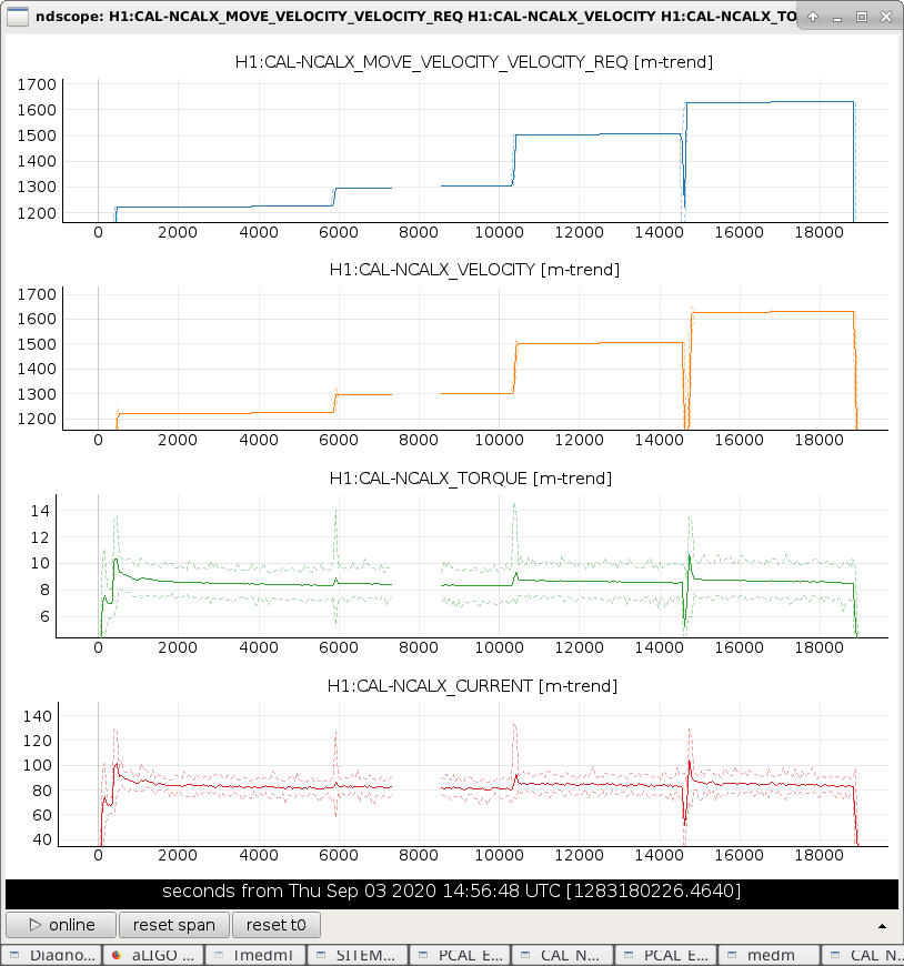
(1) The typical readback values for the motor's current draw (H1:CAL-NCALX_CURRENT) during the above excitations were
- 70-90 ct while stable at spin frequency
- 120-150 ct while ramping up in frequency
- (and we know there's a limit) at 200 ct.
We know from the precious Krishna Notes, that the calibration of the motor current readback is 600 ct = 3 Amps, or 0.005 A/ct. Thus, the numbers above are 0.35-0.45 A while running, 0.6-0.75 while ramping, and a 1.0 A limit.
(2) The typical readback values for the motor's applied torque (H1:CAL-NCALX_TORQUE) during the above excitations were
- 5-10 ct while stable at spin frequency
- 10-15 ct while ramping up in frequency
I haven't found a calibration for this channel directly. But, according to the AM8022 data sheet, there are two possible models, for which the torque constant is either 0.53 Nm/A or 0.33 Nm/A. Using the above calibrated current, that means the amount of torque exerted is either
Stable [Nm] Ramping [Nm] Limit [Nm]
- 0.53 Nm/A 0.1855 - 0.2385 0.318 - 0.3975 0.53
- 0.33 Nm/A 0.1155 - 0.1485 0.198 - 0.2475 0.33
but I'm not confident I've understood the data sheet, so don't quote me on those numbers.
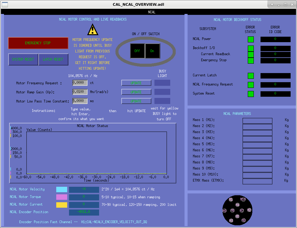
(3) One big operational thing to highlight: after hitting update on the motor frequency request, the beckhoff controller ignores any command to update until the yellow "BUSY" light is OFF. That means, if you've entered in an incorrect spin frequency too quickly with big fingers and mashed the UPDATE button, you've gotta wait until the controller is finished completing your errant request before you can fix it. So -- take your time!!
I've updated the MEDM screen to reflect all of the above information.
Attached are plots backing up my statements, and a screenshot of the updated MEDM screen.
The MEDM screen updates have been committed to the CDS userapps SVN here:
/opt/rtcds/userapps/release/cal/common/medm/
CAL_NCAL_OVERVIEW.adl
Images attached to this comment
As we continue investigating systematic error in the NCAL system, we're reminded by the PCAL team that torques on the test mass, caused by NCAL, misinterpreted as arm-length change due to the lever arm between the IFO spot position on the test mass and the center of rotation of the test mass, can lead to over estimation of the intended longitudinal force on the test mass -- especially because the NCAL is "off to the side."

As such, we need the spot positions and directions w.r.t. to center.

During this measurement, the alignment dither system was on, servo-ing the spot positions to a fixed location on the test mass. That position is determined by the Pitch-to-Longitudinal and Yaw-to-Longitudinal decoupling coefficient for the given QUAD suspension's L2 (PUM) drive.

One can use these P2L and Y2L decoupling coefficients (gains) to infer the position of the beam on the test mass HR surface.

During the entire lock stretch of this measurement, on Sep 03 2020, the gains were as follows:
    P2L = 4.3
    Y2L = 3.6

I ran the above numbers through
    /opt/rtcds/userapps/release/isc/common/scripts/decoup/BeamPosition/a2l_lookup.m
in matlab, which returned the following answers:
    >> a2l_lookup('PIT',4.3)
    Spot is -15.7 mm from the PIT center of the optic
    >> a2l_lookup('YAW',3.6)
    Spot is 13.2 mm from the YAW center of the optic
The sign convention (revealed in the notes at teh top of the script) translates these magnitudes to:
    15.7 mm in -Vertical, and 13.2 mm in +Transverse.

I aide the interpretation of direction with an ASCII art diagram:
                                             /-------------------- /
                                            /                     / |
       +V   +---------|         +V         +---------------------+  |
        ^ HR|         | AR       ^         |HR                 HR|  |
        |   |         |          |         |                     |  |
        |   |         |          |         |                     |  |
        |   |         |          |         |          13.2       |  |
+L  +T |         X-->        |  |
        +T  |  |      |         +L         |            | 15.7   |  |
            |  | 15.7 |                    |            V        |  |
            |  |      |                    |            S        | /
           S|  V      |                    |HR                 HR|/
            |_________|                    +---------------------+

After discussing the calculation with Jenne & Rick, we assume these numbers have "1 mm accuracy." We interpret "1 mm accuracy" as +/- 1 mm, i.e. for the vertical position, a "box-car" / ?uniform" / ?flat? distribution with equal probability if it being any value between the limits of (V position + 1mm) and (V position - 1 mm) and similarly for the horizontal position, a box-car distribution with limits (T position + 1 mm) and (+T position - 1 mm).
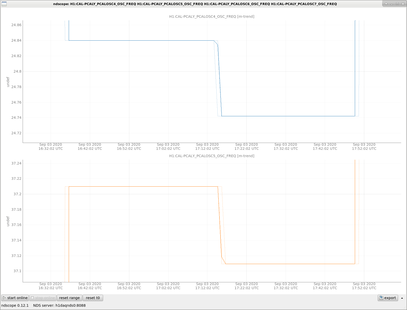
Finally gathering this NCAL/PCAL data from the frames, and I notice a clear error in in the following line:
Time (Start - Stop UTC)        NCAL 1f (ct)   NCAL 1f (Hz)    NCAL 2f (Hz)   NCAL 3f (Hz)   PCAL 2f (Hz)   PCAL 3f (Hz)
[...]
17:20 - 17:50 (n hi, p lo)     1302.331        12.4200         24.8438        37.2578         24.7422        34.1094
[...]

Namely, the PCAL 3f frequency should be 37.1094. I've confirmed this to be the case with a trend of the EPICs channel that I used to define the frequency in ndscope (see attached).
Images attached to this comment