Wed and Thursday afternoons I swapped the two flat OPO mirrors, M1 and M2. For the motivations to change these mirrors, see E2000155 (M2 has higher green transmission to make that signal more useful for intensity stabilization, the IR finesse is increased to reduce the OPO threshold which will allows us to use less green power to get the same nonlinear gain, at the expense of slightly higher OPO losses).
I used just the green beam for the swap, with Thorlabs PDs set up off the OPO platform for the reflected beam off of M1 and the transmitted beam from M2. In the transmitted path I also used a 50/50 BS and a camera to watch the cavity misalignment. Before swapping I switched the cavity scan to use the PZT that drive M4, one of the curved mirrors. This PZT changes the cavity alignment as it moves. Similar to what I saw for the M2 PZT (57304), I saw 6 full FSRs (nearly 7) while scanning this with what I think is 75 volts, in the chamber we only saw 2-3 FSRs using the full PZT range 52289.
The M2 swap (input coupler for CLF) was easy and quick, I attached the alignment jig before starting the swap. Tightening the set screws on the alignment jig did misaling the OPO a bit before I unbolted it. This mirror has two vertical pins constraining it horizontally on the OPO base, with the mirror placed using the pins and alignment jig but unbolted the vertical alignment was far off. Tightening the two bolts brought the alignment close enough to see reasonable flashes. The misalignment that remained was mostly vertical, which we don't really have the ability to adjust with the cavity mirror. I adjusted the input beam to match the cavity axis (raising the transmitted beam on the camera). We haven't done any of the cable changes yet, so the removed M2 mirror is bolted to the OPO base behind M4 until we remove it from the Dsub.
After that I swapped M1, which had a shim in O3 to help the vertical alignment. This shim prevented me from using the alignment jig, and this mirror has no pins. I placed the mirror to steer the reflected beam onto the in air PD, which had about a half a meter lever arm. This resulted in cavity flashes, and was about as fine of an adjustment to the alignment as I could make and maintain while bolting the mirror assembly to the base. After it was bolted I adjusted the input beam both vertically and horizontally to match the shift in the cavity axsis. The vertical adjustment undid some shift from the M2 swap, bringing the transmitted beam closer to the position before the swap.
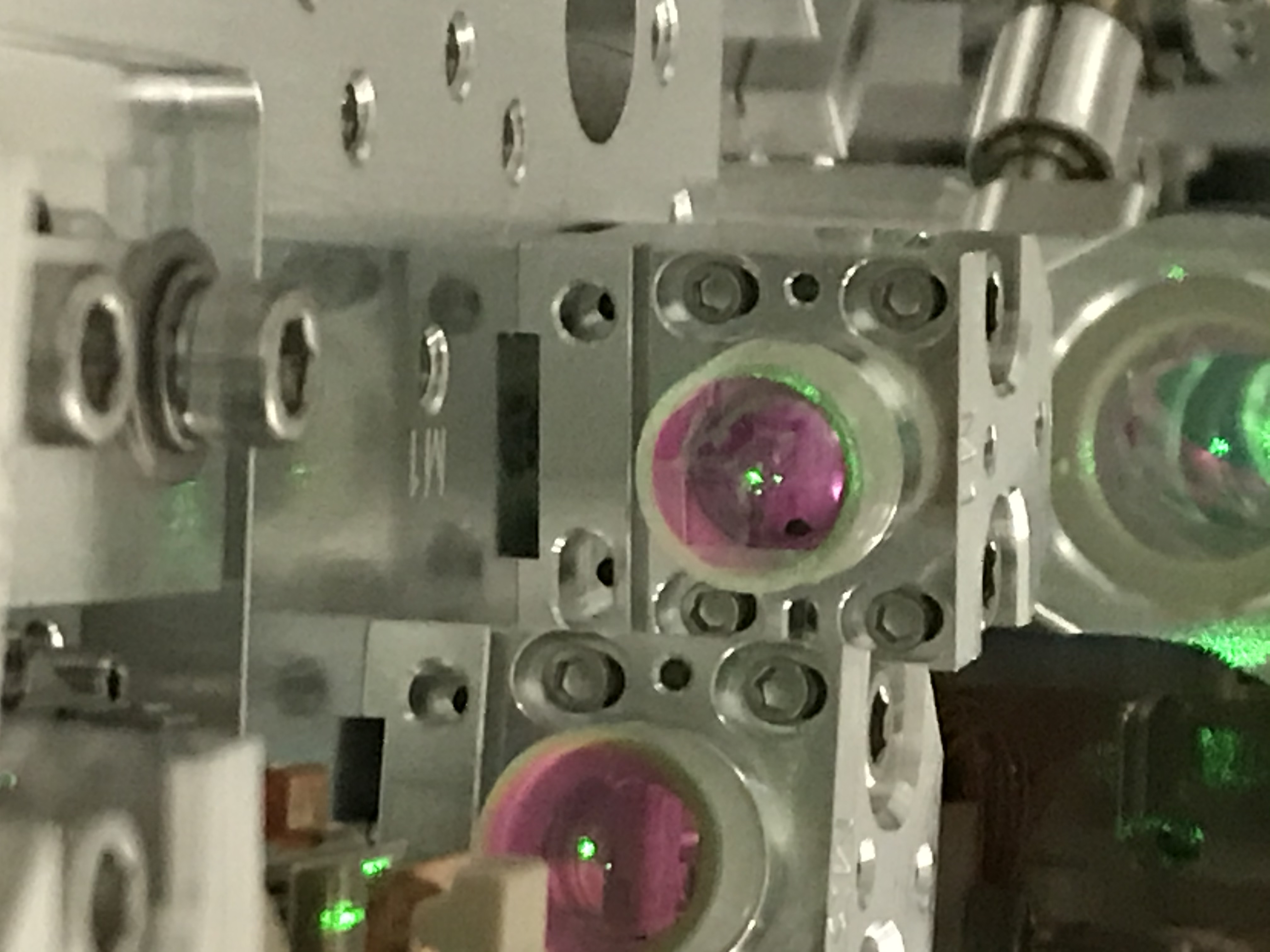
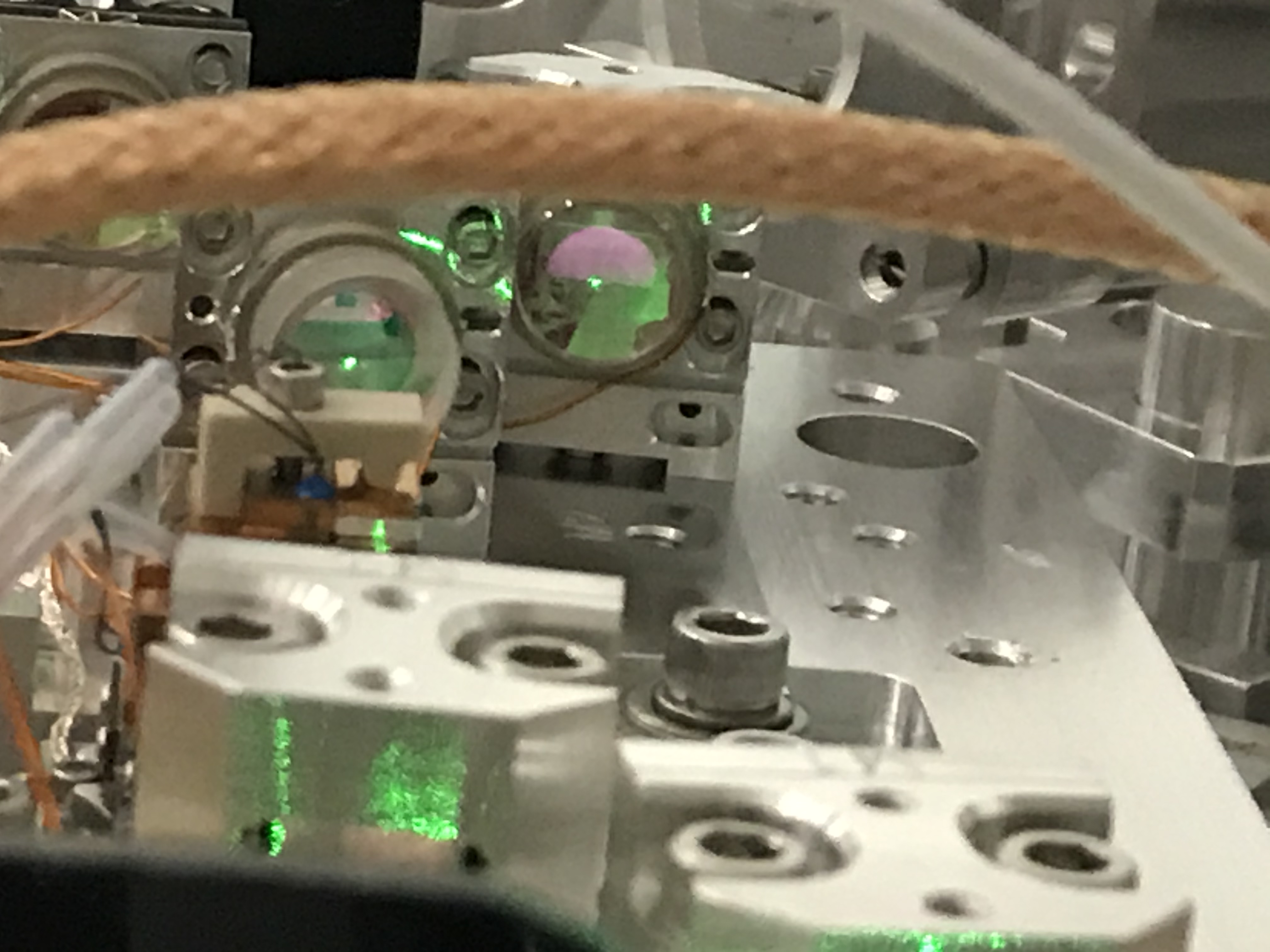
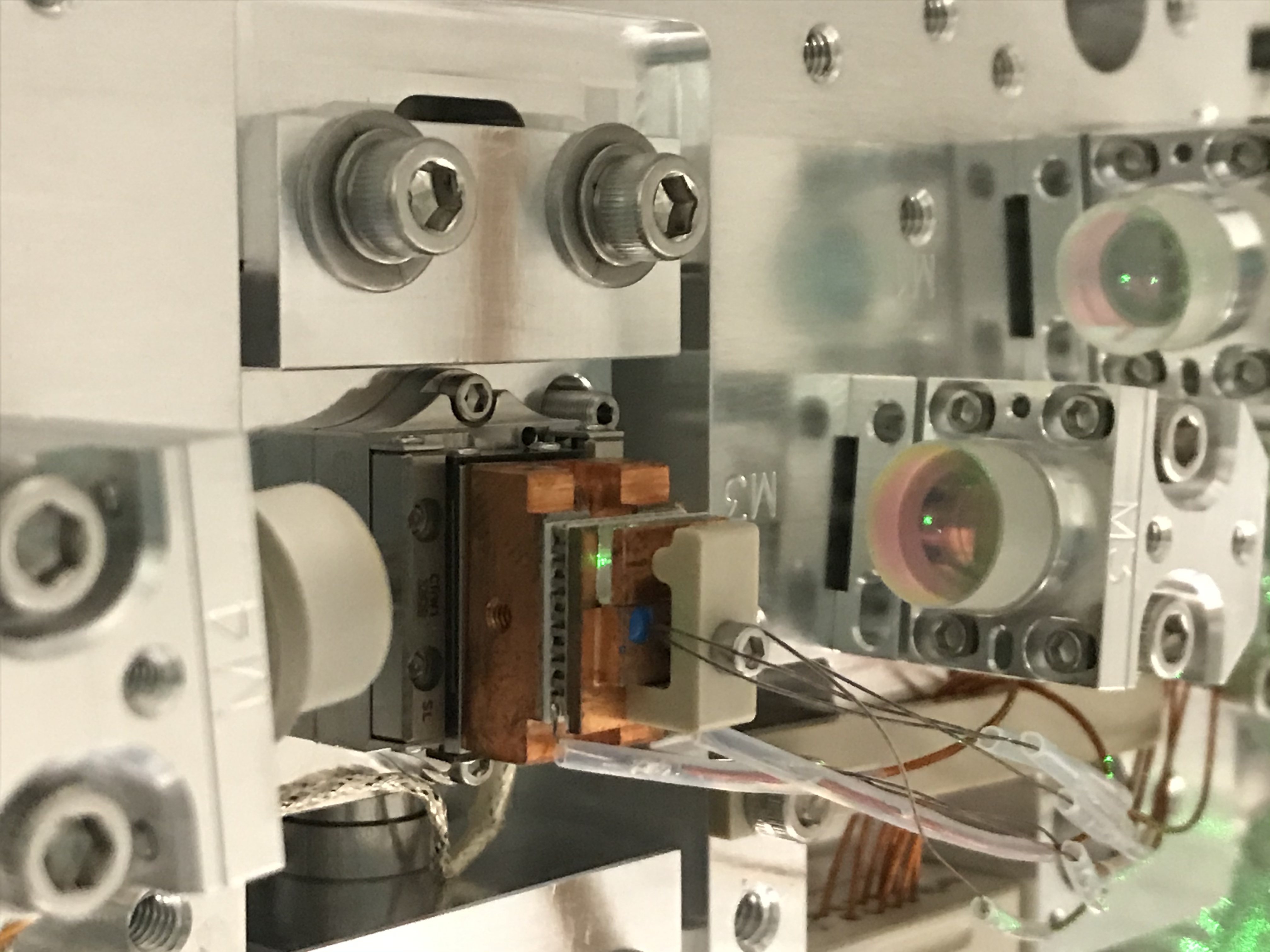
The 4 attachments are my rough attempt at showing where the beam is on each mirror, the 1st attachment is M1, then M2, ect. I still need to check that the beam is displaced horizontally not vertically when the crystal is out.
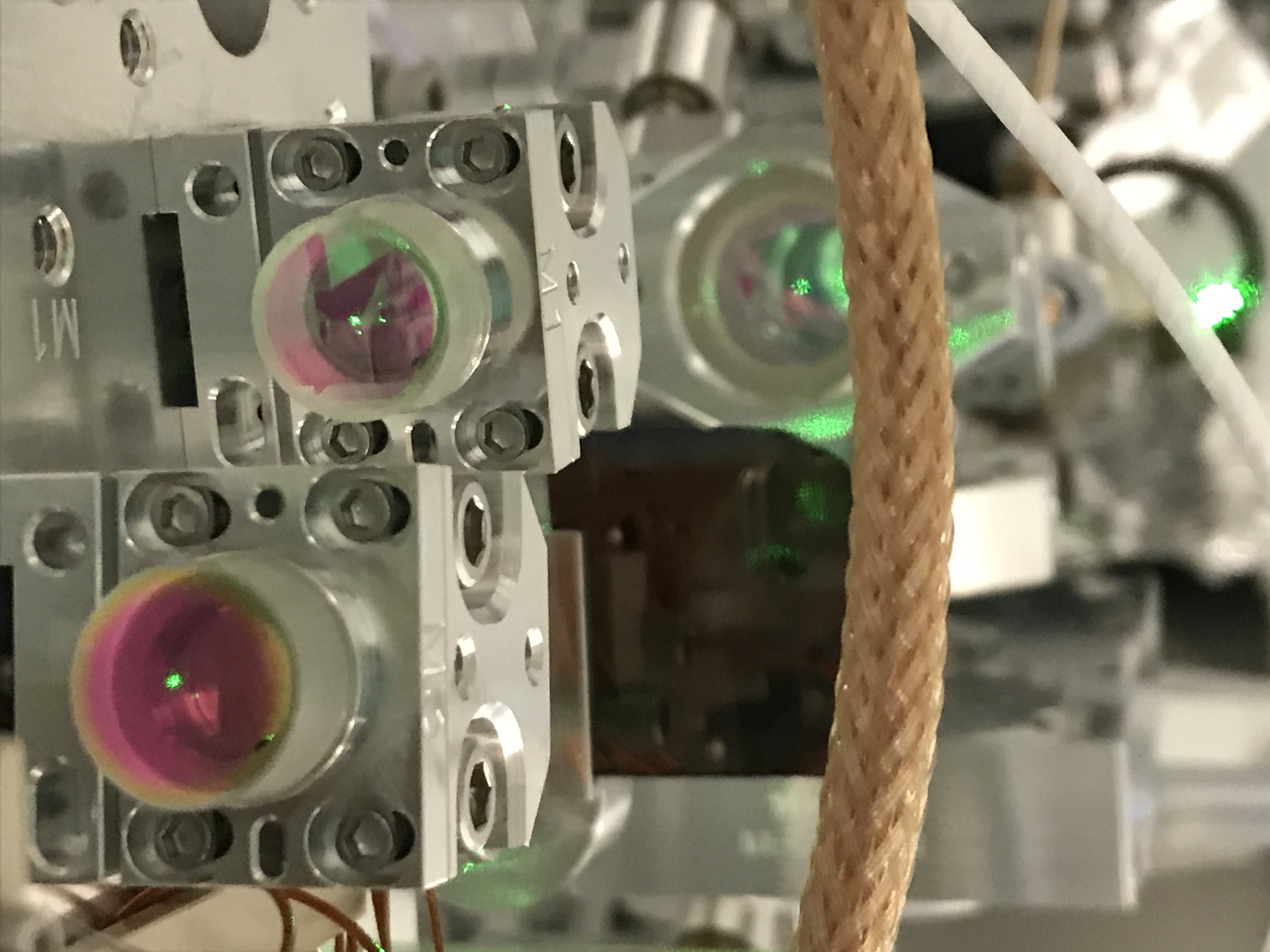
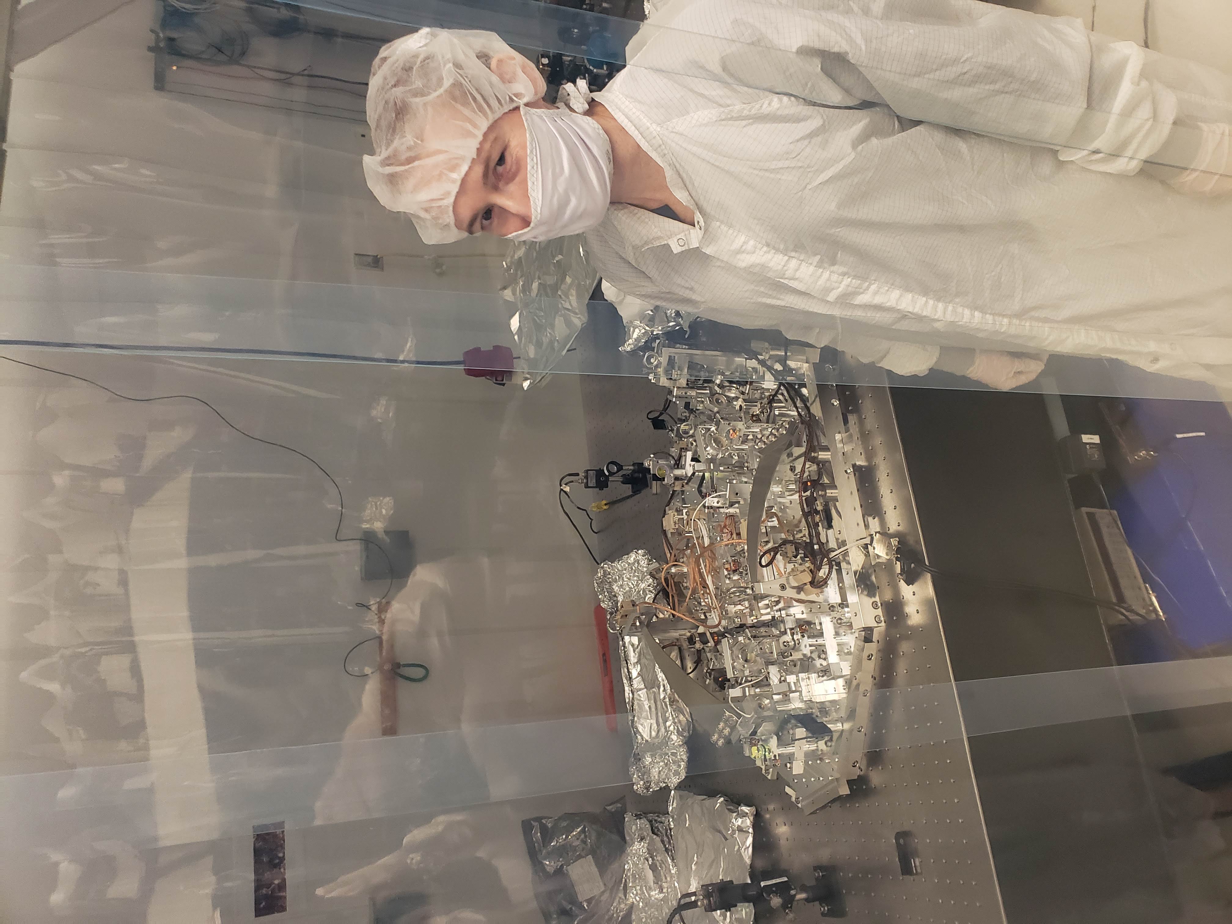
Hard at work in the lab.