To measure escape efficiency, we inject 1064 into the input/output coupler (M1) of the OPO. We have to set up a new optical path and mode matching for this, rather than use the IR path already coupled in through M2, because we can't get a good escape efficiency measurement using a port where the IR is very undercoupled.
I used the prometheus light coupled into a fiber, and collimated with thorlabs F220FC-1064. This is the same collimator used for this measurement before O3, 40500, but used a different mode matching solution in order to presevre the green coupling into the cavity (which has a different mode matching now). The mode matching solution I calculated was to place PLCX-25.4-601.9-UV-1064 (f=687mm) 1.393m from the large OPO waist, and place the collimator 1.507m from the OPO waist (so the lens is 114mm from the collimator). After adjusting manually to improve the mode matching, the lens is now at 1.1meters from the OPO waist, and the collimator is at 1.54meters from the OPO waist. This results in a mode matching of 95%, based on the 00 peak/(00 + 02 peaks) measured at the transmission through M2.
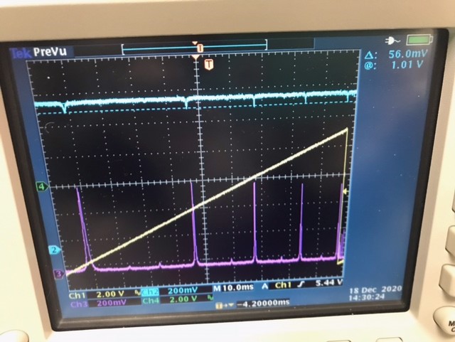
At first this set up gave confusing results for the escape efficiency, I think because there might have been some small clipping somewhere in the path between the reflection off the OPO and the diode used to measure the reflected dips. After recabling the PZTs and adding labels to the optics mounts, this clipping was made worse and then fixed. The 00 mode dip on resonance was 95,4% of the reflected power off resonance, correcting for the mismatch this means the reflected dip would have been 94% of the 00 mode power. Using the attached matlab repurposed from 40500 this gives a round trip power loss of 0.11%, dominated by the 0.1% transmission of M2 (E2000155). This results in a measured escape efficiency of 98.5%, which is ln(R_M1)/ln(R_M1*R_loss), and agrees with Lee's prediction of 1.4% escape loss in E2000155.
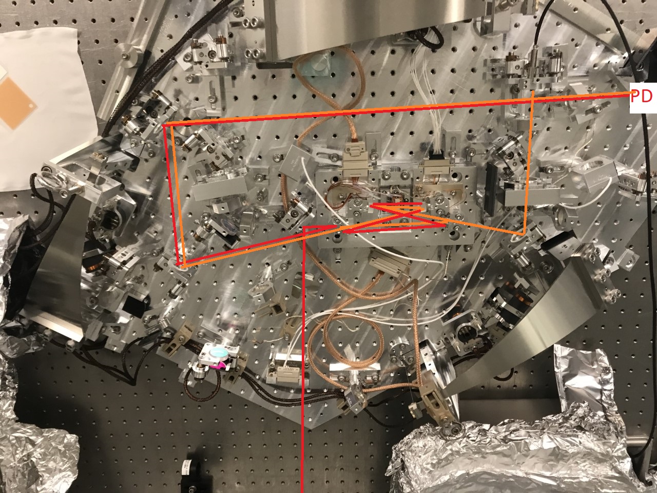
The attached photo of the set up in the optics lab is intended to demonstrate how I aligned the escape efficiency path. I started with the light from the prometheus injected to the OPO through the CLF path, (orange lines in photo) and aligned this onto a diode off the platform in the squeezed light path (marked PD). I used the fiber laser in the collimator to set up the escape efficiency path, shown in red. By co-alinging the escape efficiency path reflected beam with the CLF transmitted light, I was able to find cavity flashes. Not shown is a PD used as a transmitted PD for the escape efficiency where the CLF reflected diode would be. I've also attached the a la mode script used for lens placements.

Awesome, great news! Theory and experiment agree sometimes!![]()