It's been a while since I posted and we've made some progress on the rebuild of the squeezer for O4.
Corey has been working through cleaning the optics for the VIP + HAM7, Camilla has been assembling the optomechanics for the same, starting with VIP and will move on to HAM7 after. We have received SFI1 from Florida, and it is placed on the platform with the alignment appertures still in place. We also have the diamond fiber of the type that will be used for 532nm in O4.
Green pump to OPO (G path):
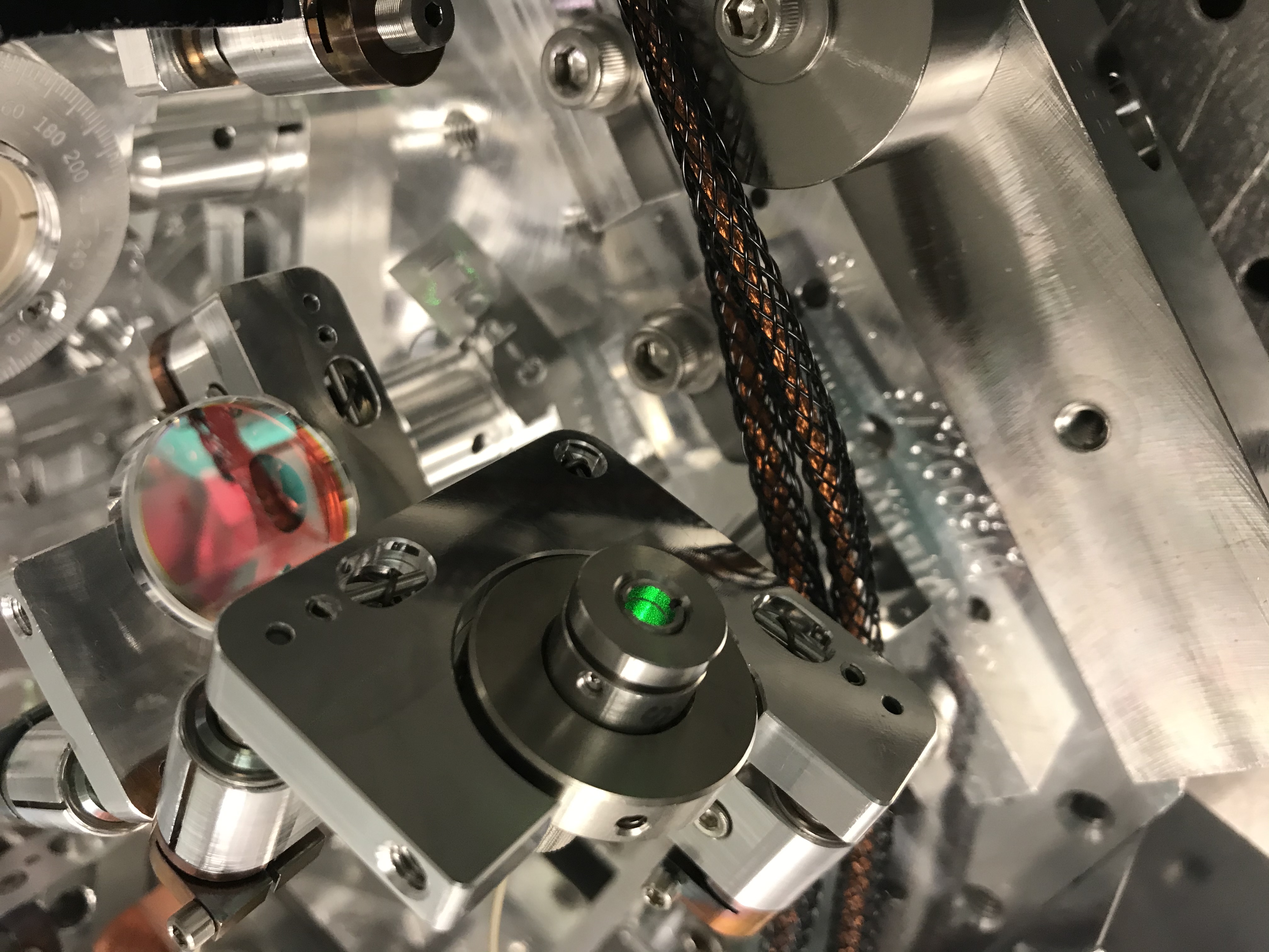
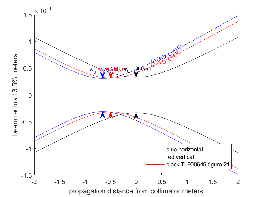
We recieved the diamond fiber for 532 from Caltech. This fiber was intended to be used in chamber, but had a problem with the RGA so we will use this fiber as a class B fiber to do the mode matching and alignment of the two green paths, then replace it with the final fibers which might arrive in mid March. The first attachment shows the way that the new collimator (micro laser systems FC3-VIS-APC-VAC SN1407) is mounted in it's adapter ring, so that the set screw on top of the collimator is accessible when it is mounted (this set screw is what you loosen to allow rotating the front of the collimator to change the lens position). I set this up with the beam leaving the VIP towards the beam profiler, and adjusted the lens to try to collimate the beam. Each time that I adjusted the lens the alignment out of the collimator shifted, which would make it difficult to do this adjustment with the beam aligned to the cavity. The 3rd attachment shows the beam widths measured out of the collimator after adjustment, the fit gives a 310um horizontal waist 0.858 meters behind the collimator and a 316 um waist -0.5 meters behind the collimator.
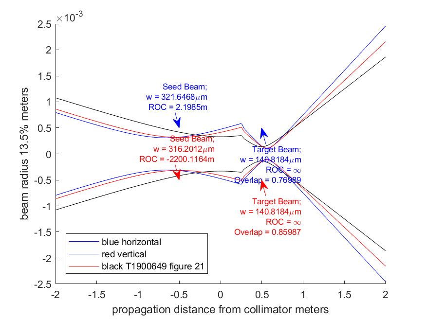
The next attachment shows these beams propagated through Lee's mode matching solution from T1900649, predicting 86% mode matching for vertical and 77% for horizontal. I placed the optics according to the distances listed in T1900649 figure 21, and trying to follow the placement of dogs in D1500302-v6 becuase the space is rather tight I found that in order to also keep the a path distances between optics close to Lee's mode matching calculation for the A path I had to iterate a few times adjusting the placement of the bases to get both paths close to their design. The final result is suprisingly good mode matching for 532 into the OPO, the 2nd order mode has about 6% of the power that the 00 mode has. There is an a la mode matlab notebook attached to this alog with the beam propagation for this path (uLaser_collimator_to_OPO_532.m)
What remains to be done for the G path: We have more freedom to adjust the polarizer angle than in O3 since the polarization monitor PD is now off the platform. The half wave plate hasn't been adjusted although the angle should still be correct for O3 this is worth checking. The angle of G:M2 hasn't been set to match the drawing, and the placement of G:L3 needs to be adjusted to have a well collimated beam heading towards SQZT7.
SQZ beam through SFI1 (A path):
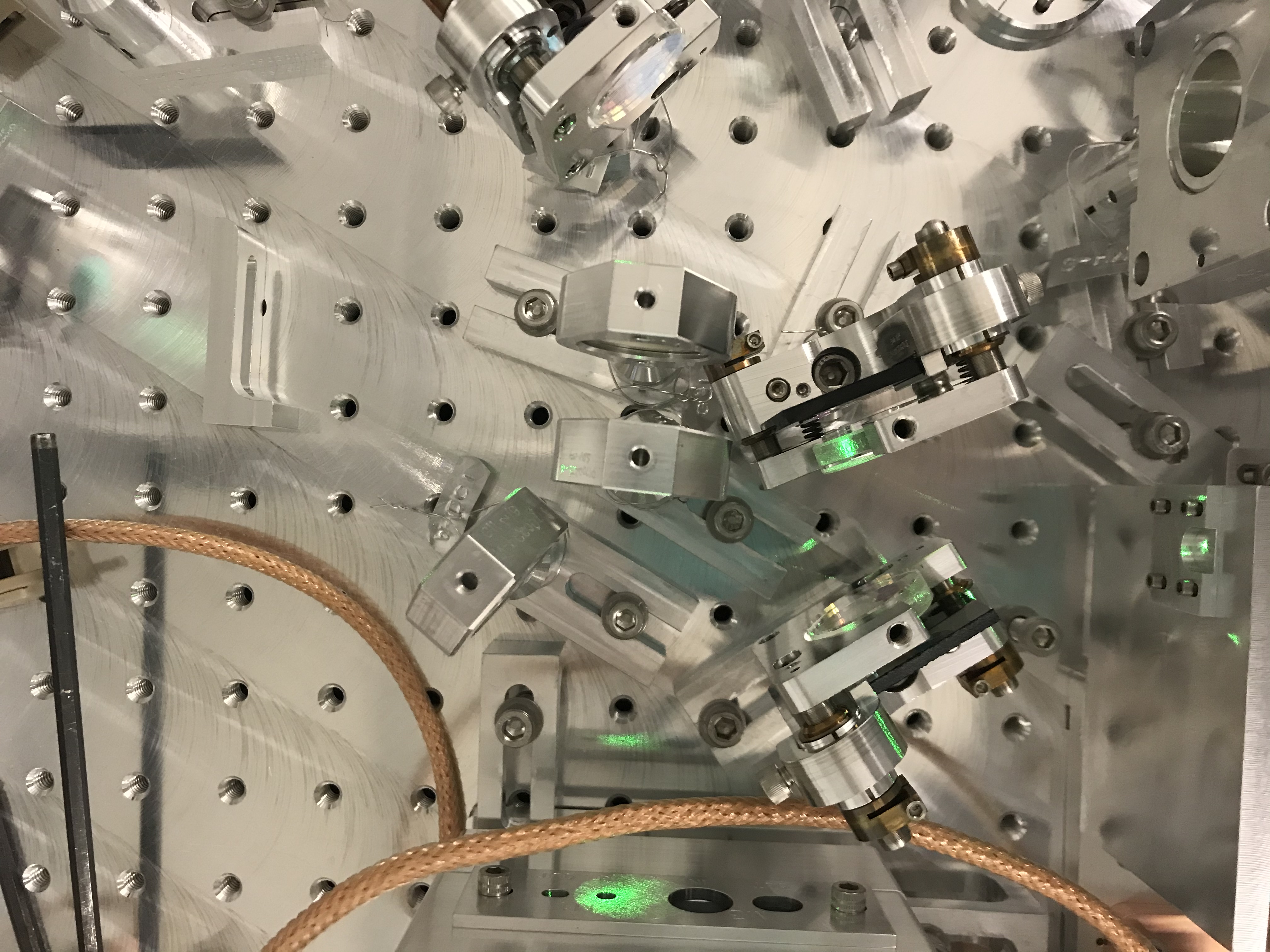
We also have the IR beam (CLF) coupled into the OPO through the F path and M2. Although D1500302-v6 shows that this path does have come changes in position compared to O3, I left the path as it was to get started and and for the refl PDH lock (57638). The PDF attachment is Lee's mode matching calculation for this path, I have tried to place the optics fairly close to the distances Lee uses in that figure, which was a little tricky because of how tight the space is and how close some of the G path optics are. The arrangement of mounts that I ended up with is slightly different from what is shown in D1500302, so I've attached a photo. I started with SFI1 placed by comparing to the bolt hole locations in D1500302-v6, and the total distance from the OPO M1 to the Faraday thin film polarizer should hopefully be within ~5 mm of what is called for in the calculation. I have left A:L1 out of the path for now, because it would mechanically interfere with the first aperture on the Faraday. With the OPO scanning, I used the transmitted IR to walk the alignment of A:M1 and A:M2 to get the beam through the first Faraday aperture and pretty close to the 2nd aperture. Once the beam was close to the second aperture, I was able to just adjust A:M2 a little bit and see the beam transmitted by the Faraday and the 3rd aperture. Having the second aperture in place was helpful for getting this beam through SFI1.
The beam exiting the Faraday is now directly hitting the side of the mount for F:L1, so I will need to move the F path before checking the Faraday transmission.
Checking change to mode matching for F path (CLF matching to OPO):
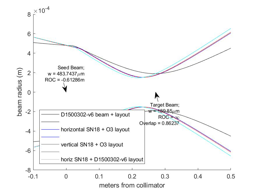
The mode matching for the F path from before O3 is described here: 40362. Maggie measured the output modes of these Lightpath 1064 collimators and posted her data and script here, we have SN18 installed. For SN18, Maggie measured a vertical waist of 315 um 0.337m in front of the collimator, and a horizontal waist of 321um 0.343 meters in front of the collimator. Based on the information in figure 23 of T1900649-v8 the mode used for the calcaulation is a waist of 456um 0.207meters in front of the collimator, resulting in a waist of 190um (radius) 45 mm before the HR surface of M2. In O3, the +150mm ROC lens was 44mm from the collimator, and M2 was 269mm from the collimator.
Using the O3 layout and Maggie's measurement of collimator SN18, we would expect 95% mode matching, which seems reasonable for what we had in O3. Using Maggie's measurements and the new layout from figure 23 which would allow us to avoid interference with the squeezer beam leaving SFI1, we would predict 85% mode matching from the vertical measurements, 86% from horizontal (check_1064collimator_SN18_new_CLF_layout.png). Based on D1500302-v6 it seems that we have room to move F:L1 almost a half inch further from the collimator before it's mount would start to interfere with the beam leaving SFI1. Moving it forward would improve the mode matching to 88% or 89% for horizontal. The main consequence of mode mismatch of the CLF to the OPO is increased shot noise on the CLF refl diode, so this level of mode matching is probably OK. There is a second a la mode matlab notebook attached (CLF_Matching_to_OPO.m), with these beam propagations for the F path.