Summary: The A path on the VIP (OPO to filter cavity, through SFI1) is set up, with 96/97% overlap with the design beam parameter after double passing SFI1, and the SFI1 double passed transmission is 99% or 98% measured with a power meter.
Details:
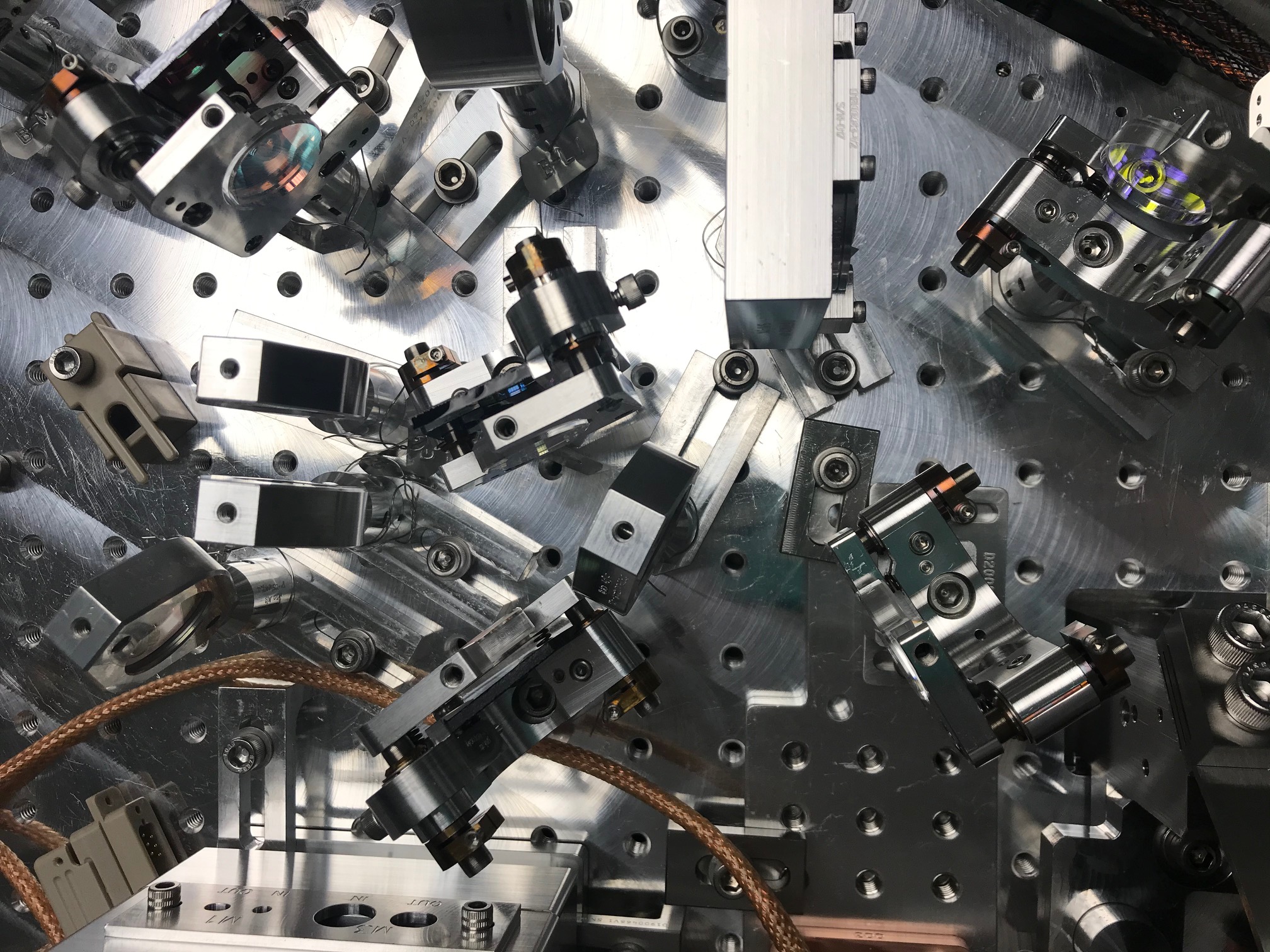
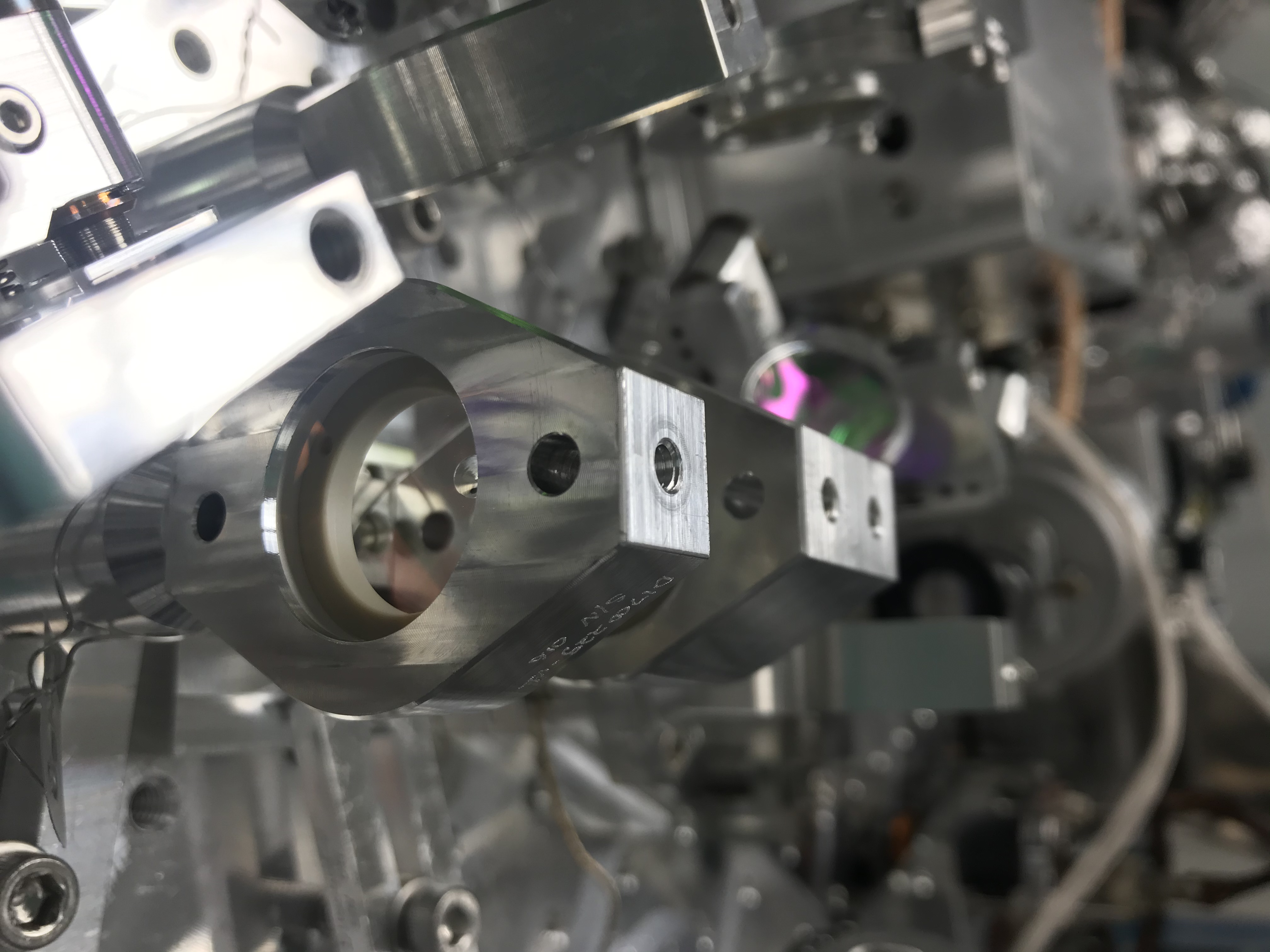
We got the new 9 pin Dsub connector from clean and bake, which Filiberto connected to the lens translation stage, so we have all the connectors installed on the VIP now. I will attach photos to this alog of the way in which the bases are arranged, because it is slightly different than what is shown in D1500302 and I have also changed things a little since the photo posted in 57906.
For the mode matching, I followed figure 16 in T1900649. With the base of A:L1 as shown in D1500302 I couldn't get the lens closer than about 35mm from A:M2, so I rearranged the base of G:HWP1 and the dog on that corner of SFI1 (A:L1 photo) This means that A:L1 did not interfere with apperture 1 on SFI1, so I was able to place the lens before removing the first aperture. With the apertures still installed, I placed A:DC2 and A:M3 according to their distances from the mode matching figure 16. I placed a retro reflector close to 178mm from A:M3, and an iris right in front of it as a reference to preserve the alignment from the SFI1 apertures (retro reflector photo). The flipper mirror shown there was useful for directing the beam onto a monitor PD (useful for manualy finding resonance for PDH locking) and the beam profiler. I moved B:M1 out of the way so that I could see the reftro-reflected beam transmitted through the thin film polarizer (on the SFI2 side), and placed a second iris on that side of the platform (iris shown towards bottom of overview photo). The plan was to use these two irises as a reference for the alignment through SFI1 given by the appertures installed in Florida, so I then removed the apertures.
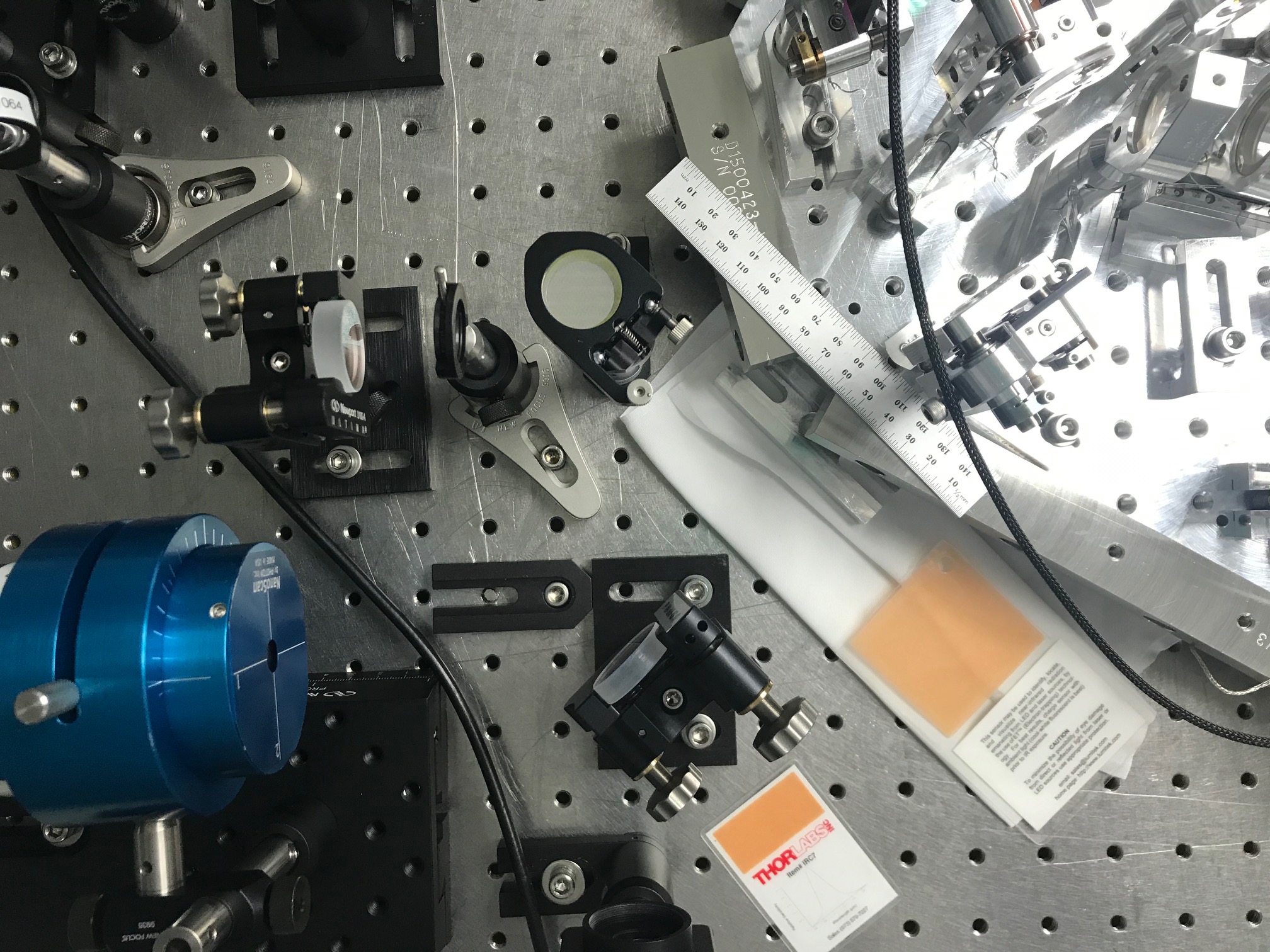
With only A:L1 in place, I locked the cavity and tried to measure SFI1 transmission using a power meter. I consistently measured a transmision of ~110%, which I think was caused by the beam being larger on the power meter after SFI1 than before the thin film polarizer. As I added A:L2, the beam was deflected vertically (with no lens there was a small upward deflection of the beam leaving SFI1, just under 1 mm over the ~195mm from the Faraday output to A:DC2). Since we don't have any vertical adjustment of our lens mounts, this meant that the beam was moved on the iris right before the retro reflector, and I would need to adjust the alignment of the retro reflector to get the beam back on the SFI2 side iris. I did some more re-arranging of bases and added an in air iris on a class A base (which isn't class A anymore) right at the output of the Faraday. I felt more confidant of not loosing the alignment reference from the apertures placed at Florida with this iris in place (SFI output iris photo). I used this additional iris to realign the retro reflecting mirror and found that the beam was well centered on the SFI2 side iris after that, this iris also comes in handy for setting up the isolation measurement.
Compared to the drawing D1500302 Lee's mode matching solution from Figure 16 has A:L2 further from the Faraday output, and I found that I could get better overlap with the design beam parameter by moving it further. This created a mechanical interference with the lens translation stage, the double lens mount, and A:DC2. I moved the double lens mount, which is intended to hold an apperture to capture the p polarized beam leaving the Faraday, from A:L3 to A:L2, which saves space since the translation stage mount is bulky along the beam line, and because the lens is now less centered on the translation stage. (Menaning that when the translation stage is in the center of it's range, the lens is now closer to A:DC2 compared to if it were mounted with a normal lens holder.) Unfortunately, I chipped A:L3 while making this swap by attempting to tighten the lens mount retaining ring while the optic was not sitting flat (chip photo).This chip is on the flat side of the optic and near the edge, so it would probably not be a problem, but we might swap the lens in any case.
I have taken beam profiles with only L1, L1+L2, and L1+L2+L3 installed after A:M3, and on the other side of the platform on the SFI2 side of the TFP. The overlap with the design beam after double passing the A path in this way is 96% for horizontal, and 97% for vertical. I believe that this can be improved by moving A:L2 closer to A:L3. I will return to this mode matching after finishing the Faraday isolation measurement, and post more details of the beam measurements then.
Edited to add transmission measurements:
With the three lenses in place and the OPO locked, I measured the power incident on the thin film polarizer from the OPO and then the double passed beam on the SFI2 side of the thin film polarizer. I got 0.8mW out of the OPO and measured 98% double pass transmission once, 99% transmission the next time. This was done with 91mA applied to the TEC, the measured resistance of thermistor 1 (pin 1-6) was 10.28kOhm, the measured resistance of thermistor 2 (in 2-7) was 10.15kOhm. According to Paul and Ryan, thermistor1 is the preffered one to use in chamber although temperature differences of 100Ohms aren't large enough to matter much for these measurements.