Summary: The two measurements I've tried of the Faraday isolation are both limited by scattered light, we have at least 32dB of isolation from a single pass of the Faraday, and measured at least 29dB of isolation from the double pass. The single pass measurement may be limited by scattered light from the rejected beam which will be baffled once we have the appertures, and the double pass measurement is probably limited by the beam being too large in my set up, which could be improved if it seems necessary.
Setting up the measurement:
The set up I used is similar to both the diagram Lee made on page 20 (SFI1 isolation) of E2000551 and the set up that Maggie described in her wiki for the O3 VIP.
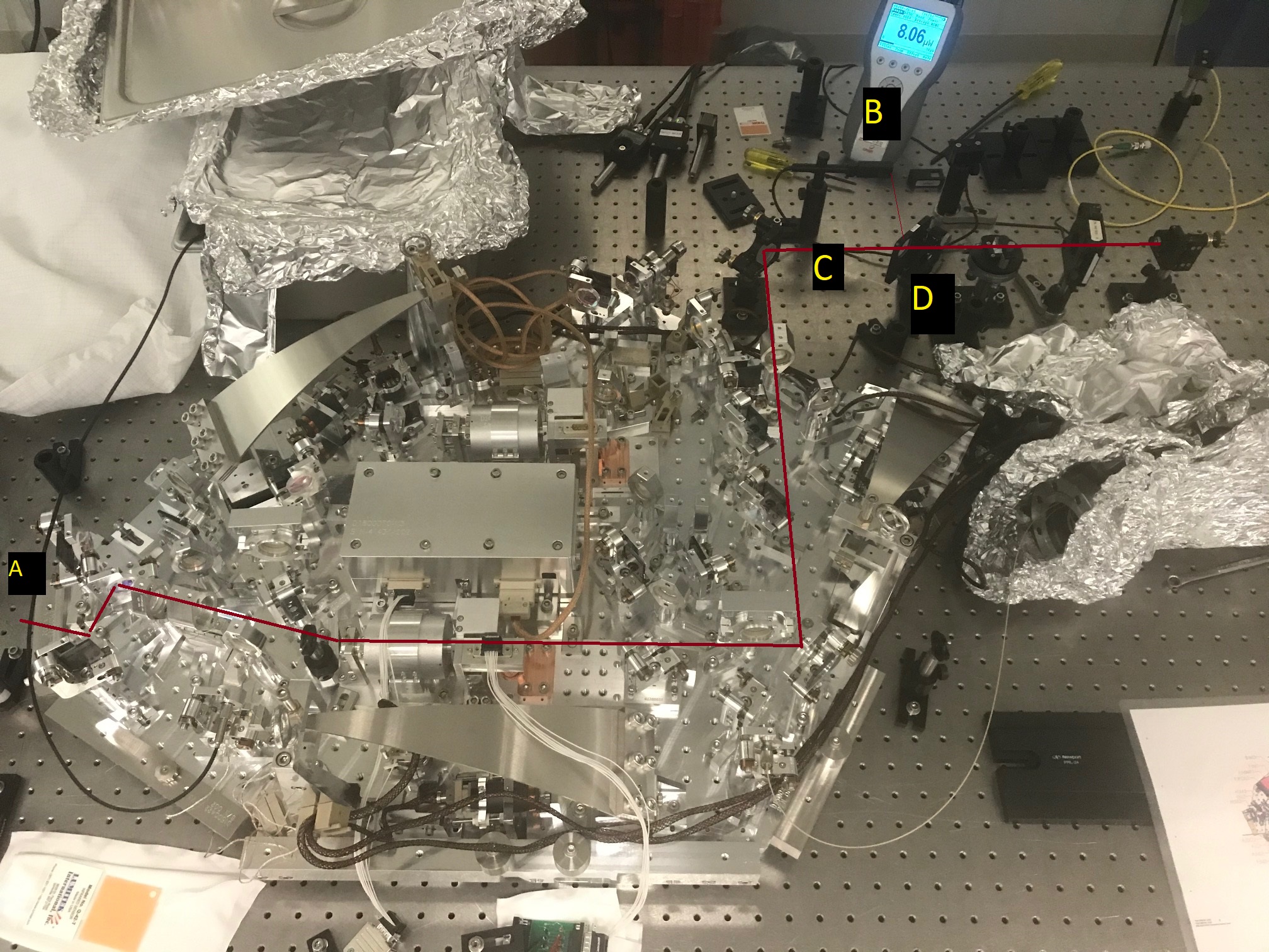
I used a thorlabs fiber and collimator (F220FC-1064), a PBS at the output to transmitt only p polarization, followed by a 50/50 BS for 45P. I did not use a chopper for this measurement; we will rely on measurements made at Florida to estimate the actual transmission and isolation of the Faradays, these power meter measurements are just to confirm that shipping and installing them didn't cause problems. A steering mirror was used to send the light from the collimator towards the B:M1 from the back side of the VIP. Although I didn't do a careful job of measuring the mode, I moved B:L1, (+350mm ROC) near where the beam first reaches the platform from the back side to make the beam size smaller through the Faraday. The first attached photo shows beam path with letters marking the location of power meter measurements.
The thin film polarizer will only transmitt p polarized light, which comes out of the Farday at a smaller angle than the s polarized light that the A path is aligned to. In order to set the alignment of the beam from the fiber collimator along the a path, I placed a half wave plate on one of the class A double bases that has been replaced by a single base for O4. This was between the rotator and the thin film polarizer, as shown in the second attached photo. With the wave plate set so that there is roughly equal power in the s and p beams transmitted by the Faraday, a fraction of the retro reflected s-pol beam will again be p-pol at the TFP and be transmitted to the B path, making it possible to find the return beam in reflection off the 50/50 BS (location labeled B in the first photo, the non-rejected beam), and set up a power meter.
I found that the easiest way to get this beam aligned was to leave the prometheus light coupled to the class A IR fiber injecting into the OPO through the CLF path (F path), and scan the OPO. With the half wave plate mixing s and p as described above, I could co-align this flashing beam with the fiber laser beam out of the collimator. To make measurements I moved the low insertion loss thorlabs fiber from injecting into the class A fiber to the collimator, since it is useful to have the higher power from the prometheus.
Measurements:
First I measured the refelctivity of the 50/50 beam splitter by taking measurements at locations C and D, the reflectivity was D/(C+D)= 52.4%
The next measurement that I tried was to measure the power at location A, the beam transmitted by the Faraday, first maximized by rotating the temporary half wave plate, then with the wave plate removed. With the waveplate removed, most of the power is in the p-polarized beam. This beam is currently hitting the side of the lens mounts for A:L2 or A:L3, (because the apperture to capture it isn't here yet), so there is scattered light around the location of the power meter which could be limiting the isolation estimated this way. The ratio of the transmitted power without the wave plate to the maximum power is a way to estimate the isolation of the Faraday in this direction, 0.12mW/184mW, 352ppm or -32dB of isolation.
The next measurement was to measure the power returning to the 50/50 beamsplitter from the retro-reflector. This beam should be rejected by the Faraday twice, and indeed it was difficult to measure. In my first attempt I had the lens B:L1 in roughly the position where it will finally be to match the beam to the IFO, this gave a large beam through the Faraday with the collimator beam, and I could see a halo of scattered light around the beam when I had the half wave plate in place, the halo remained when the half wave plate was removed, but dissappeared when I blocked the path between the thin film polarizer and the rotator.
For this measurement, the product of the isolation from the two Faraday passes is B/(D*(1-R)) [or B/CR] using the measured reflectivity and the powers measured at the locations in the photo. With 232mW reflected off the BS at location D, I measured 129uW at location B with no half wave plate. This power was unchanged by blocking the retroreflector downstream of the Faraday, but dropped to 13uW when the beam was blocked between the TFP and the rotator, indicating that backscatter off the Faraday was limiting the measurement. I believe this backscatter was caused by the beam size being too large through the Faraday; when I first attempted this measurement with B:L1 set in its design location the beam was even larger and I measured 240uW of this backscatter.
Even though the measurement is dominated by backscatter, it gives us a minimum isolation of two passes of the Faraday, which is 0.1%, or -29dB of isolation.
I added a 1m focal length lens to the path for this isolation measurement, which gives us a smaller beam through the SFI and less scattered light for the measurement of the non-rejected (retro-reflected beam), which gives us a better isolation measurement of -43dB.
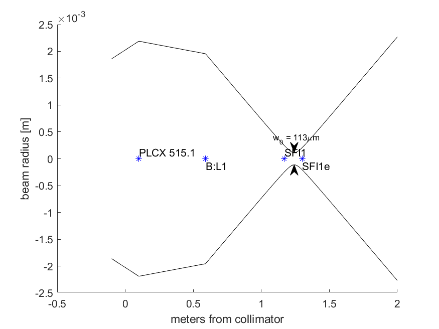
The attached plot and alm notebook contain the beam propagation for this path, there is a PLCX-25.4-515.1-UV-1064 100mm from the F220FC-1064 collimator, B:L1 (+350ROC) is on the edge of the VIP which is 590 mm from the collimator. The Faraday rotator is between roughly 1.17 and 1.3 meters from the collimator, where the beam radius is now less than 300um.
With 176mW in location D, I measured 19.9mW in location B with the temporary half waveplate installed, 4.3uW with the HWP removed, and 2.4uW with the HWP removed and the retroreflector blocked. This gives us an isolation value of B/[D(1-R)] of 51ppm or -43dB using the 4.3uW non-rejected beam. The measurement with the retro reflector blocked indicates that this measurement is still limited by some scattered light (or room lights), but the 43dB value is probably adequate.
For reference, I've added a node to the document tree for the SFIs E2100077; the test report from Florida for this Faraday is in the dcc at E2100094.