Sheila has been placing the optics and lenses to set up the O4 configuration of the OPOS platform for the filter cavity. We have great ambitions for the mode matching quality, especially since SAMS active wavefront control are incorporated into the telescope designs. It is very challenging to adjust mode matching once the platform is in chamber, so we're hoping to get very high matching to the design in T1900649.
Sheila's matching so far is around 96-97% with the nominal design, so I wanted to help investigate what might cause the discrepancy. In particular, the OPO cavity design and OPOS telescope lenses have tolerances on the radius of curvature, so if they deviate from the nominal, I want to adjust the design at this stage. So far it looks like that is not the case.
Sheila supplied me with a rather well annotated a-la-mode script with profiling measurements after lens1, 2 and 3. I translated those into my telescope code for Figure 16 in T1900649 to take a look.
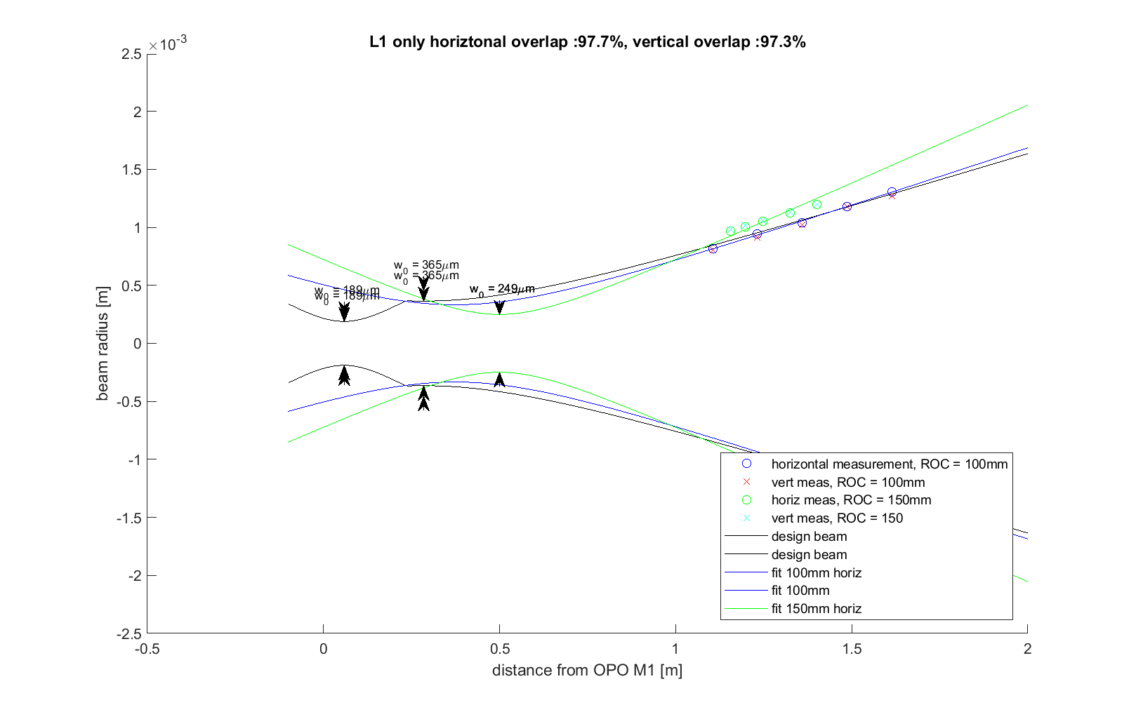
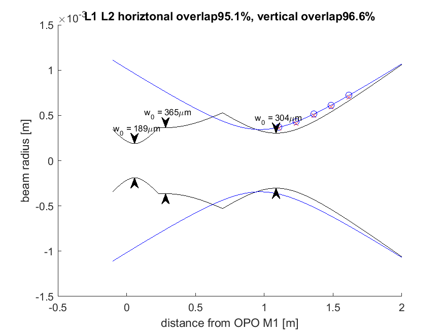
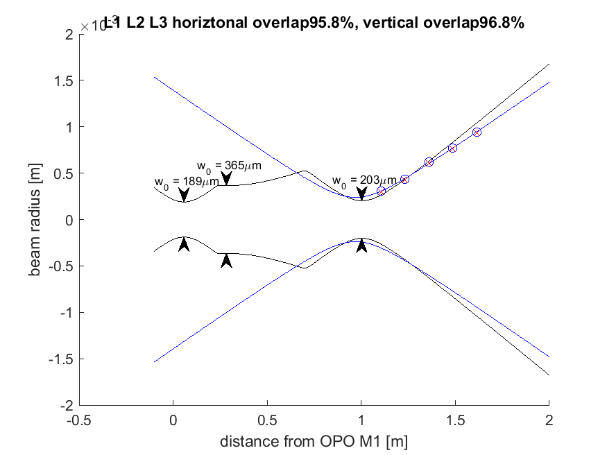
VIPtoZM1.pdf: shows the current setup using nominal lens positions. THe OPO/cavM1M2 and FC/cav traces are the nominal design which are well-matched. The MM_L1 is the profiling measurement after L1 and injected at L1 in the code. Correspondingly, the L1L2_A-D sequence are a series taken after L2, where L2 placement was adjusted. D is the current setting, then MM_L1-L3 is after L3 was placed.
You can see from this that the placements are pretty good and the measurements are internally consistent. The L1L2A-D sequence shows that the lense actions are weak on these small, collimated beams as the Raleigh-range of every before/after beams is long compared to the placement accuracy. This is why the L2 "AWC" translation actuator won't do all that much and why it is good to improve the matching now. The plot ends at ZM1 and the difference in beam waist size at ZM1 will translate into a difference in beam size and iROC at ZM2. The ZM2 SAMS actuator can only compensate for changes in iROC for beams at the optic, not for the beam size on the optic.
It looks to me like the matching issue starts at L1. Comparing the MM_L1 beam to the nominal cavM1M2 beam shows that either the lens is a bit stronger than we expect, or it is placed a bit too far down the beam. This is because at ~9 inches along the x-axis, right after L1, the iROC of the beam is below zero (the nominal collimated design), so it must either have dropped further than expected through too large a focal length, or it must have started with the green/blue modelled beams being at a lower iROC to start with, by L1 being further than expected. To check the latter, I moved L1 in the code and it has to move an unrealistic ammount, and it cannot fully recover the matching.
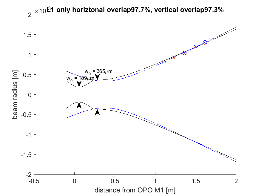
Now the matching between MM_L1 and cavM1M2 is about 98.7%. From this, I think we need to swap in a 100mm ROC lens and see if things improve. If not, then we can try a 150mm and I'll have to check if the OPO cavity mode can be reasonably adjusted to explain the difference. The fact that the beam size at L1 given the MM_L1 measurement is appropriate, but its iROC is not, suggests that the lens is to blame and not the OPO cavity mode, since the cavity mode has to propagate to M1 and would most likely end up a different size.

I found a ROC+100mm lens which was removed from the O3 VIP, and prepared to swap A:L1 for this. I tried to check the focal length of A:L1 in the optics lab by imaging the ceiling lights, I found that I got the sharpest image with the lens ~212mm from a piece of paper with both the new ROC +100 lens, and the lens which was installed as A:L1. Just to make sure there wasn't some problem with this quick measurement, I did the same thing with a PLCX-25.4-77.3 from CVI, in this case I found the image was sharpest at ~170mm from the paper. I think that this test should have been able to distinguish between a +100mm and a +75 mm lens. It seems most likely from this that A:L1 is a +100mm lens.
I'm not sure what that means for the mode matching calculation and measurements.
For future reference, I'm attaching here the a la mode notebook that has this first set of measurements and the plots it produces.
The measurements with L2 at different locations are commented out but start on line 64 of the notebook.
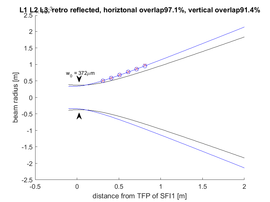

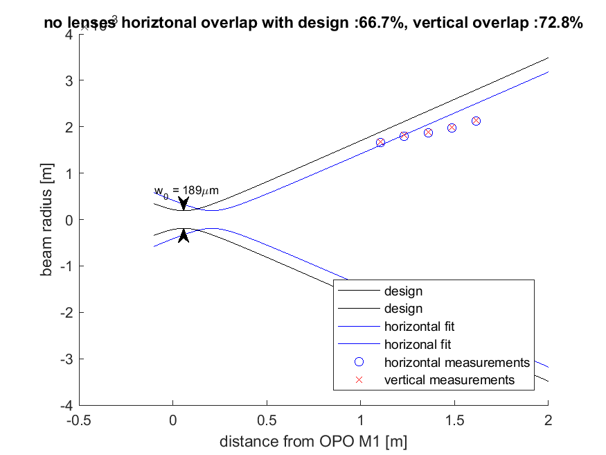
Keita and I attempted to measure the mode out of the OPO with no lenses installed, after SFI1. I think that this measurement is not reliable, possibly because of clipping (the beam profile did look reasonable, but the measurements do not give a reasonable fit.) I am attaching a plot and the measurements are included in lines 28-32 of the attached notebook, just for the record.
We also tried replacing A:L1 with a 150mm ROC lens. This gives rather poor overlap with the designed beam, 76% overlap.
While we were placing this lens, we realized that the beam is very off center on A:M2, near the edge of the mirror close to G:L2 (see D1500302). This means that the distance measurements we had previously used need to be revised a bit. With the +150mm curved lens in place, we estimate that there is about 35mm from where the beam hits A:M2 to the curved surface of the lens, and about 60mm from the curved surface to the TFP. Measuring from the corner of A:M2's mount to the near side of the lens mount, is 21mm.
The resulting waist with the 150mm lens in place is 249 um at 0.499meters from the OPO (this is based on measurements taken of the beam relative to A:M3 and assuming that the distance from the OPO to A:M3 is as designed.) These measurements with the 150mm lens in place are at lines 106-107 in the attched notebook.