Keita, Sheila
This is an update on the mdoe matching from the OPO to the filter cavity, called the A path on the VIP. For earlier alogs about this see first round of measurements 58207 comments and Lee's updated model with new lens solutions in 58342
To start with Keita and I worked to center the beams on the optics better, in particalar the beam on A:M2 was close to the edge. We reinstalled the SFI1 apperture 1 before we moved this mirror, so that we had a total of 4 appertures (the three irsises I had placed earlier described in 58126 in addition to apperture 1) to help restore the alignment through SFI1. After that we used a ruler to make some careful distance measurements of the VOPO as built.
| measured distance from last optic [mm] | measured distance from OPO M1 | design distance from OPO M1 | |
| A:DC1 | 112 | 112 | 109 |
| A:M1 | 67 | 179 | 180 |
| A:M2 | 30 | 209 | 214 |
| SFI1 TFP | 89 | 298 | 303 |
| SFI1 output | 261 | 559 | NA |
| A:DC2 | 212 | 771 | 767 |
| A:M3 | 64 | 835 | 827 |
| retroreflector at desired waist position | 179 | 1014 | 1003 |
We didn't take into account that the path length through the Faraday is changed by the index of refraction of the materials in our ruler measurements. The design distances are taken from Lee's attachments to alog 58342, our total measured distance from the OPO to A:M3 is 8mm different from the design. What we really want to acheive with the mode matching of this path is to have the beam parameter leaving A:M3 heading towards the filter cavity match the design, which means having a waist 176mm from A:M3. If we achieve that, with a slightly different distance between the OPO and A:M3, that would be fine.
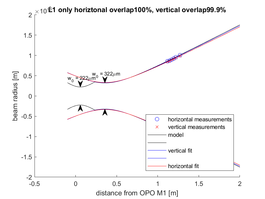
After re-centering we looked at fitting the lenses on the VIP with Lee's option 1 and option 2, we decided to try Lee's option 2 because moving L1 to the option 1 position seemed difficult because of how close it needed to be to A:M2. We placed A:L1 and took a set of measurements after A:M3, this agrees well with the new model. The attached plot was made using the measured distances, but the overlap is also very good if we assume that the distance from the OPO to A:M3 is the designed distance (better than 99.8% overlap for horizontal and vertical in either case). The attached png shows the measurements and model with only L1 in place. L1 is placed with the curved surface facing the retaining ring, which is how we have been in the habit of mounting the plano convex lenses. We tried to place the curved surface 25mm fro the center on M2.
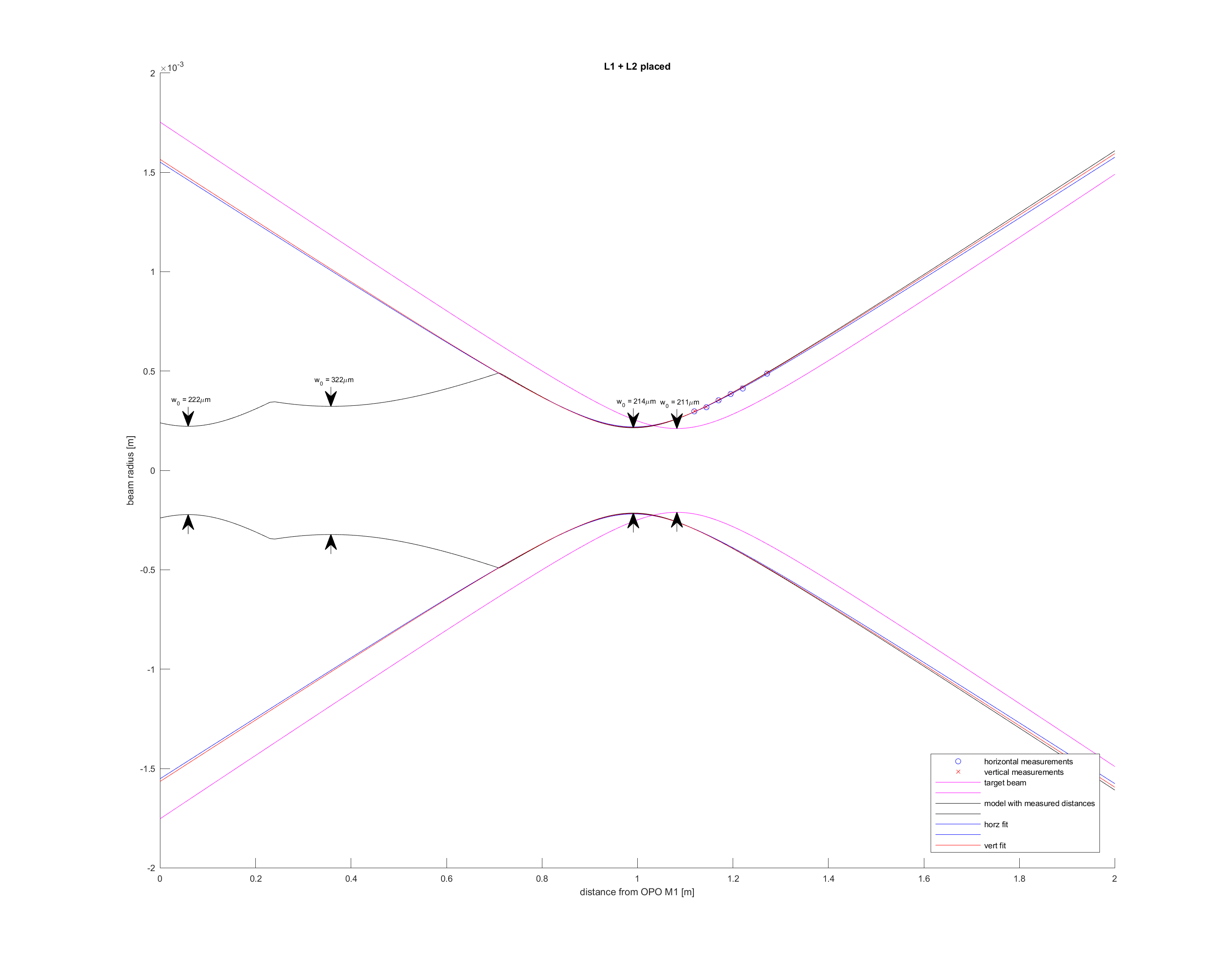
After this we mounted a +100mm ROC lens that we removed from the O3 VIP to the translation stage, which has the double lens mount and conical apperture as well. I placed this at about 50mm before A:DC2, but it will need to be moved. The 2nd attachment shows that the model agrees very well with the measured beam with the second lens in place, but that it isn't a great match to the desired waist which is shown in magenta.
The attached alm notebook has measurements taken for L1 installed only on lines 53-54, L1 + L2 at the center of the translation stage on lines 116-117, and with L2 about 65 mm from A:DC2 at the far edge of the translation stage on lines 132-133 (this data isn't plotted here).

I attached the wrong alm notebook above, the right one is attached here.
Also, A:L1 curved surface is approximately 25mm from A:M2 (on TFP side), and A:L2 curved surface is approximately 60mm downstream from A:DC2 (on SFI1 side).
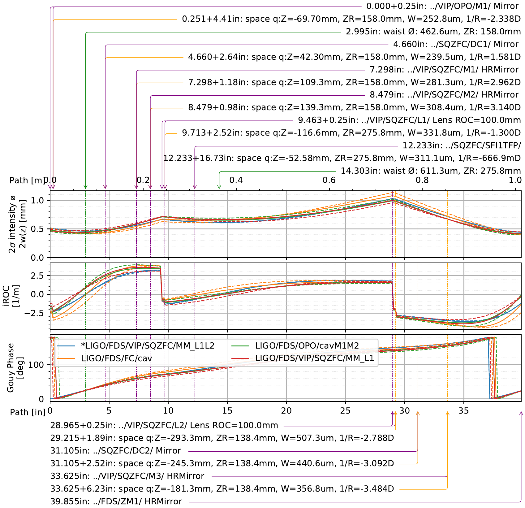
Ok, With this data I updated my models to use the full table of distances 58426_989p.png. I get that the matching of the L1 measurement to the FC+telescope is 98.2% and the L2 measurement is 98.9%. My plots also incorporate the astigmatism expected from the FC telescope (ZM2 AOI of 2.5deg and ROC of ~0.85m). You can see that the matching between the FC (orange) and the MM_L1(red) and MM_L1L2(blue). From Sheila's plots you see that the waists are the same size, but not on top of each other, so in principle we can move ZM1 or ZM2/ZM3 to adjust telescope distances. I'd rather avoid that if possible though.
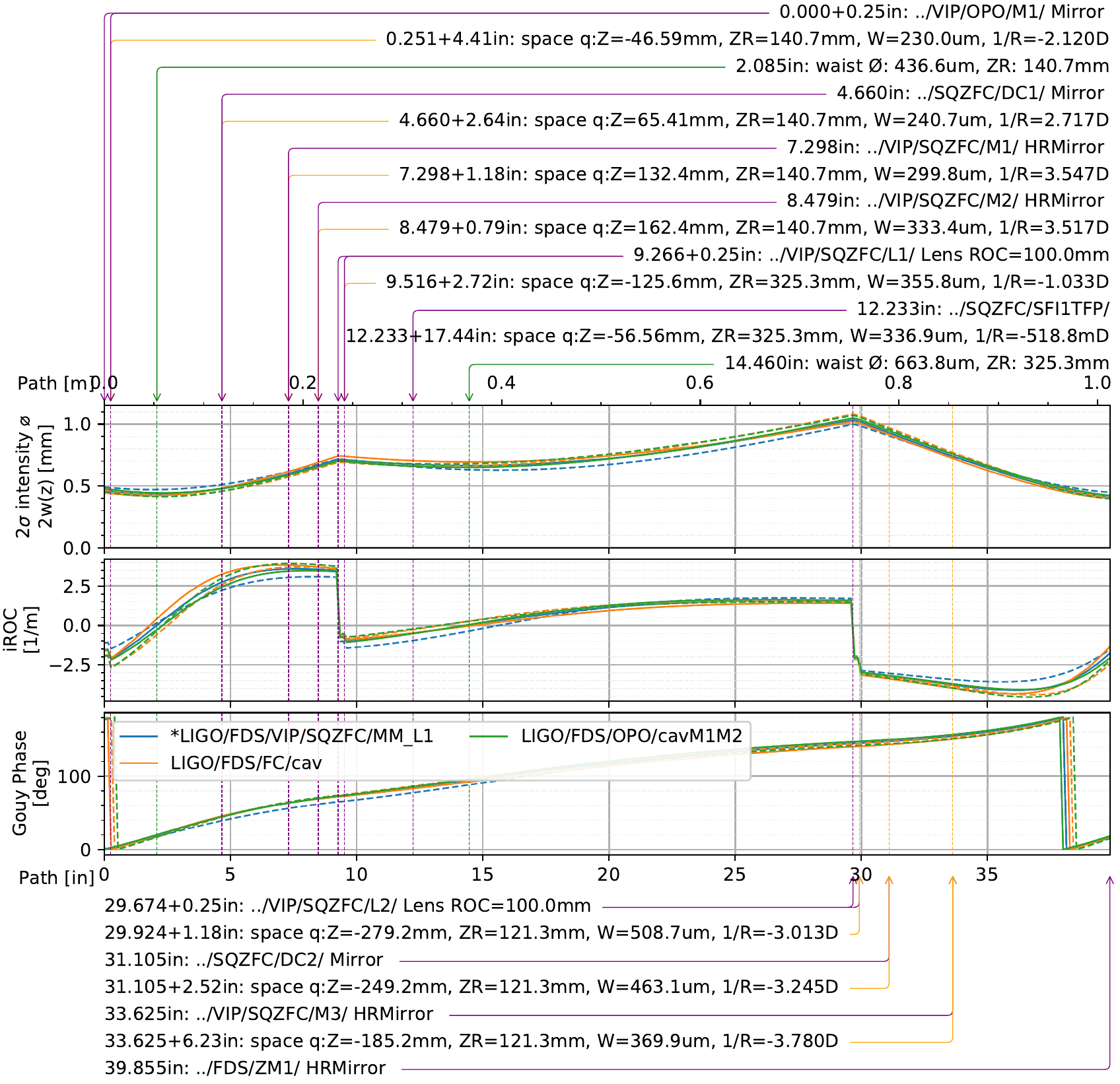
For one final nudge to improve it. I suggest moving L1 5mm closer to A:M2, and then L2 from ~48mm to A:DC2, to be only 30mm from A:DC2. With that, the L1 measurement is 99.3%, very close to the max I ever get due to astigmatism of ~99.5%. That layout is in 58426_993p_nudged.png