Keita, Sheila
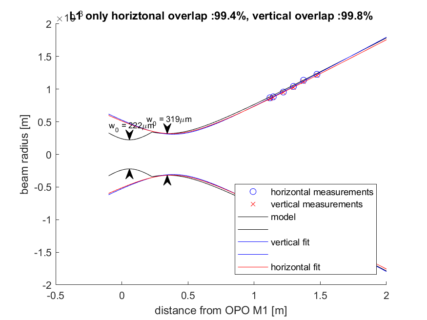
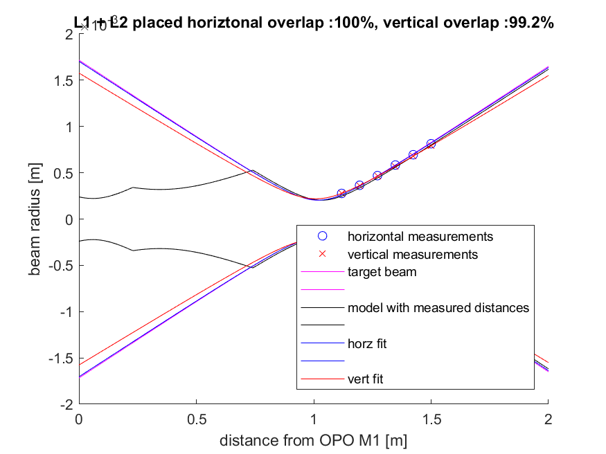
Yesterday afternoon we went into the optics lab and implemented the nudge that Lee suggested in 58474. We started by checking our alignment references with A:L2 removed, before moving A:L1 which can change the alignment through SFI1. We moved A:L1 closer to A:M2 by about 5mm, and after the move attempted to remeasure the distance. The beam is still off center on A:M2, hitting the optic closer to the OPO side of the platform than the SFI1 side, which may have caused us to underestimate the distance in our first set of measurements. We measured 17mm from the top corner of A:M2 to the close side of the A:L1 lens mount, which we estimate gives us about 25mm from A:M2 to A:L2. This is the same distance as what we estimated previously, 58426, but we are sure that the lens is now closer to the OPO than it was for that measurement, by about 5mm. The first plot shows the design path in black, with A:L1 a +100mm ROC lens placed 229mm from the OPO M1. Blue and red are measured paths, and overlap with the beam parameter from Lee's second attachment to 58474 is 99.4% vertical or 99.8% horizontal.
We placed L2, also now a +100mm ROC lens, 30mm before A:DC2, which now limits the actuation range that we can use from the translation stage. When we place L2, the beam is deflected vertically so we loose the use of the iris right before the retro reflector. We had difficulty placing A:L2 while reproducing the alignment on the aperture on retro reflected beam in transmission of SFI1's TFP. We attempted to make sure the beam was centered by projecting the beam using the flipper mirror to the end of our nanoscan rail, this is useful when placing the lens on the translation stage because we can move the stage back and forth over its range and make sure that the beam is not deflected, to check the centering. I had previously placed this translation stage without the apperture installed in the other side of the double lens mount, with the aperture installed we had difficulty installing this without moving the beam on the aperture for the retro reflected beam after the TFP.
The second attachment shows the target beam, the model of the beam propagated from the OPO, and our measurements, which agree well with the desired beam parameter leaving A:M3. Measurement data with L1 only are on lines 56-59, with both lenses installed are on 124-126.

Note: Above I wrote: "which we estimate gives us about 25mm from A:M2 to A:L2." That was a typo, I meant A:M2 to A:L1
We were able to solve the alignment difficulty that we had using a set up with a camera pointing to an iris that Keita set up. I will let him explain the method, but summarize the background here.
SFI1 came from Florida with three appertures installed, which we used to set the alingment of the beam in the forward direction. As described in page 17 (SFI1 alignment) after aligning the beam through SFI1 and the retro reflected beam, I placed an apperture off the platform in front of the retro reflector, and on the other side of the platform for the beam transmitted by SFI1's TFP. This was done before placing the mode matching lenses. When placing A:L2 (the lens in the translation stage), the beam was deflected vertically, so we had to adjust the retro reflector. Once we did get the mode matching set, we had difficulty getting the retro-reflected beam to return to the iris in transmission of the TFP without clipping somewhere in the Faraday. We believe that part of the problem was that we placed these irises without the mode matching lenses so the beam was large which limited the acuracy of placing of the irises (and the retro reflector alingment). Keita's method insured that the retro reflected beam was truly retro reflected before we placed A:L2. This allowed us to place A:L2 and reproduce the horizontal alignment without adjusting the retro-reflector (we still had to adjust the retro-reflector pitch because of the .
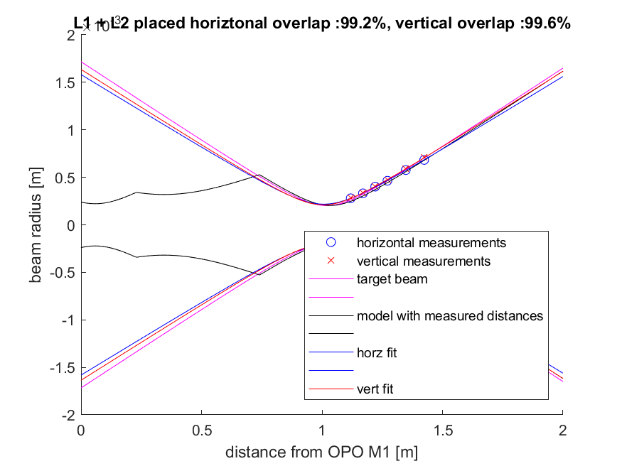
Since we removed and replaced A:L2 several times in this process, we remeasured the beam heading towards the retro reflector. The final position of A:L2 puts the front of the double lens holder 27mm from the corner of the A:DC2 mount. The attached plots show the mode measured with and without L2 (the L1 measurement is the same data as above), with A:L2 we get good overlap with the mode heading towards the filter cavity in the second attachment to 58474.
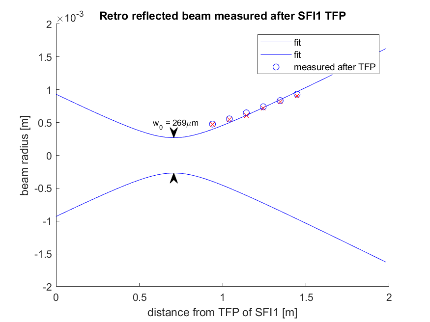
We moved the nanoscan to measure the beam in transmission from the TFP for SFI1, which is the beam we now need to mode match to the IFO. These measurements are in lines 182-184 of the attached alm notebook. These measurements give poor overlap (~90-93%) with the beam parameter we expect from Figure 17 of T1900649. I think this is not suprising, since the beam parameter incident on the TFP from the OPO side will be different with our new solution from alog 58474. We measured a waist of 269um at 707mm from the TFP for the horizontal beam, and 281um at 708mm from the TFP.

The alignment difficulty Sheila noted was solved by making sure that retro reflection is actually retro reflection (within the accuracy of a small fraction of mm). In this case, this was done by setting up a temporary iris between TFP and Faraday rotator. You can use the same technique to make sure that the beam is retro reflecting unless the return beam is significantly smaller than the input beam. (This is the technique we used for TMS telescope alignment).
Anyway,
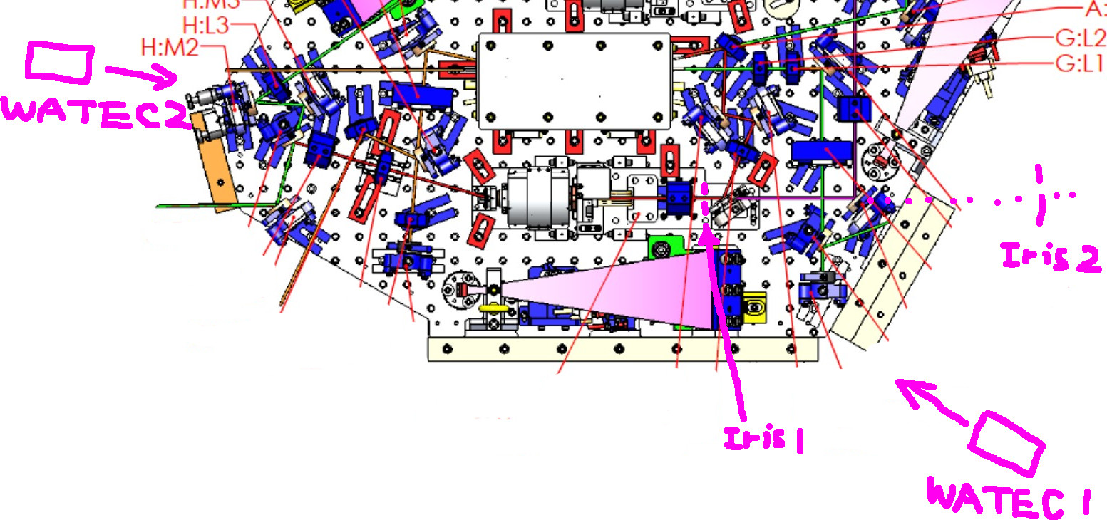
- Put an adjustable iris on an adjustable pole (these are dirty) on a sacrificial class A baseplate and place it between TFP and Faraday rotator. (IRIS 1 on the cartoon.)
- Set up two WATEC cameras (WATEC1 and WATEC2 in the cartoon) looking at the front and the back of the iris. We used 50-150mm (??) zoom lens and we had to use 10mm spacer for WATEC1 and 5mm for WATEC2 in order to focus on the iris, but of course that depends on your lens and your camera placement.
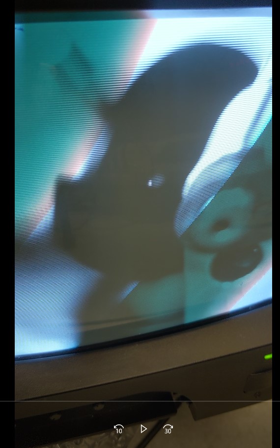
- Adjust the focus of WATEC1 for IR while scanning the OPO at about 1Hz. Too fast and you cannot see that on the camera. When the camera focuses on the visible light, due to dispersion IR is not in focus, and it makes it difficult to tell if the beam is clipping on the iris. 2nd attachment shows the mis-centered iris. Notice how big the aperture is.
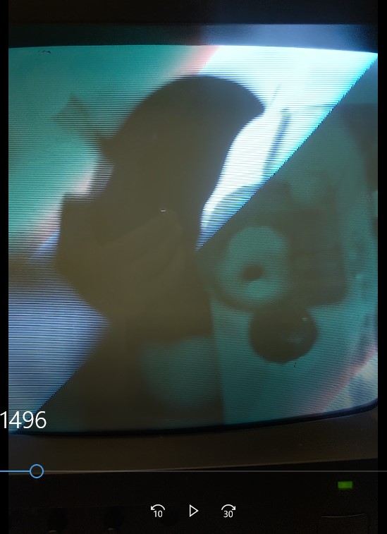
- Adjust the position of the iris until the IR glow is not just on one edge of the aperture even when the iris is set to the smallest aperture (the beam should go through the iris). Clamp down the iris and double check again. 2nd video is after the adjustment. Notice that the aperture is almost completely closed but the beam still goes through it.
- Open the iris, remove A:L2 from the path (note that we're not using A:L3).
- Adjust the retro reflector and use the IR viewer card to see if the beam is roughly retro reflecting.
- Misalign retro reflector a bit to make sure that the return beam is clipping on the iris and adjust the focus of WATEC2.
- Closed down the iris a bit and adjust the retro reflector. Iterate until the IR looks like a uniform circle at the edge of the iris. Now the beam is retro-reflecting w/o A:L2.
- Earlier, Sheila placed another iris on the optics table for the beam coming through TFP (Iris 2 on the cartoon). Adjust the position of iris2 so the beam is centered.
- Insert A:L2 to the path. Ideally all you have to do is to adjust the lateral position of the lens to recover retroreflection, but in our case the beam was also deflected in PIT, i.e. the beam height was not at the center of the lens. That's OK, just adjust horizontally as good as you can.
- Adjust the retroreflector mostly in PIT (but tiny YAW adjustment is OK) while monitoring WATEC2. You have to close down the iris1 to see the beam because, with the proper mode matching, the beam is tiny.
- Enjoy the fact that the beam goes to the center of iris 2.