christopher.wipf@LIGO.ORG - posted 00:32, Monday 25 March 2013 (5873)
End Y slow controls signals jumbled
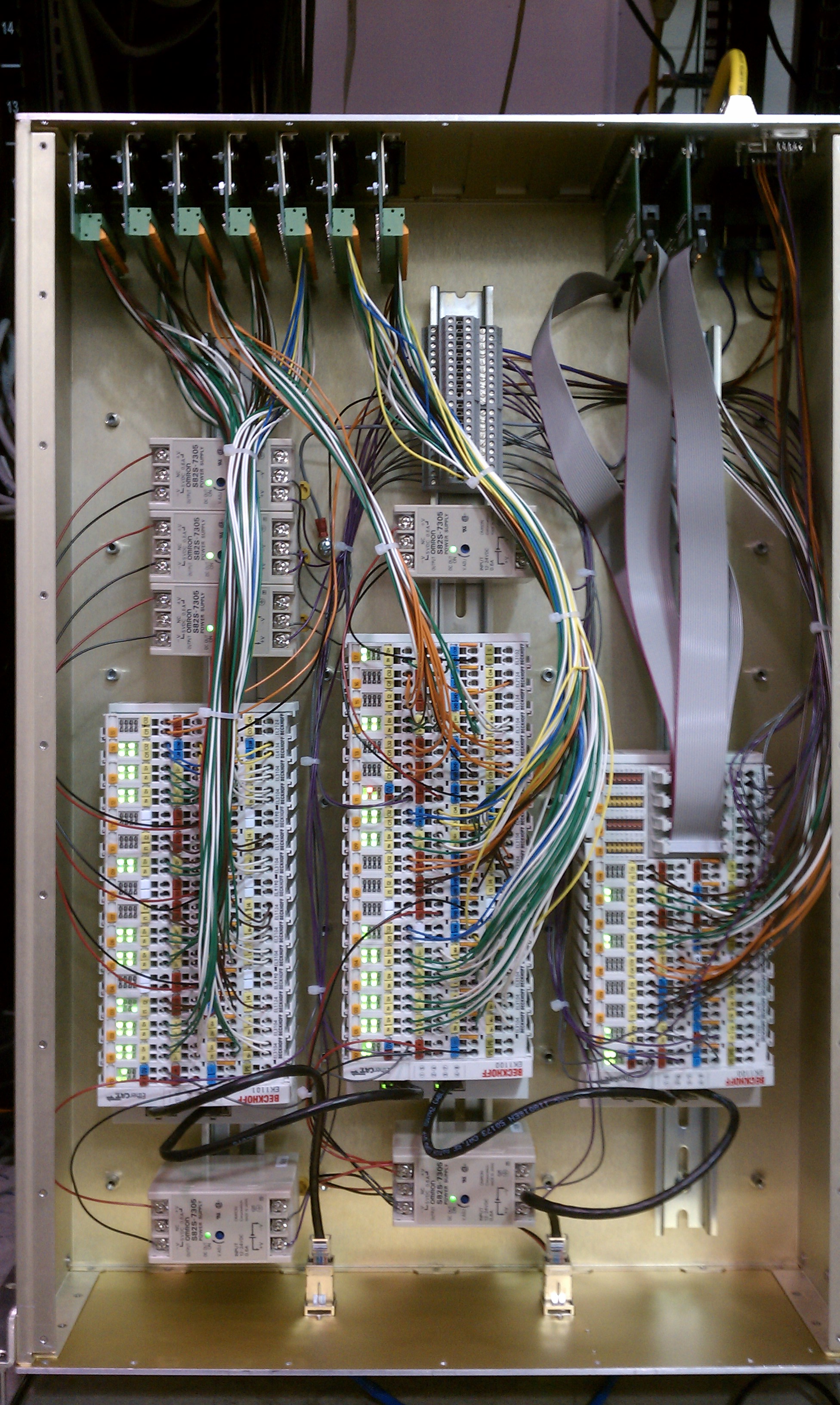
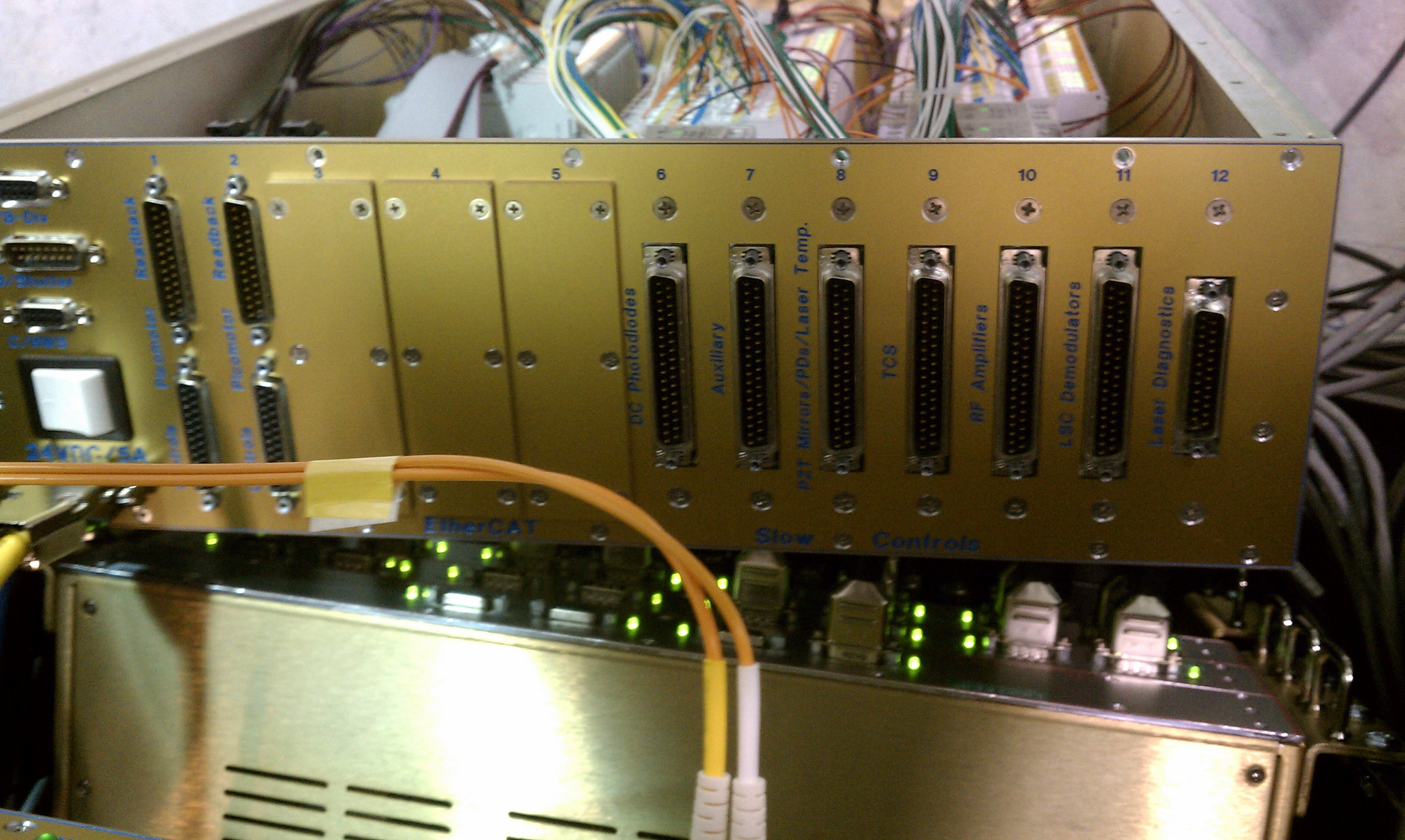
(Sheila, Max, Chris)

On Friday we uncovered a snafu with the slow controls cabling at the Y end.  The connector labels engraved on the rear panel of the "End 2" EtherCAT chassis (Exhibit A) do not agree with the chassis wiring plan (Exhibit B).  Upon opening the chassis it appeared that the internal wiring to the Beckhoff modules was done according to (B), whereas the external cable runs had been connected relying on (A).  Here's a table showing the correspondences:
| Port | Wiring plan | Rear panel description |
| 6 | Auxiliary | DC Photodiodes |
| 7 | PZT Mirrors/PDs/Laser Temp | Auxiliary |
| 8 | TCS | PZT Mirrors/PDs/Laser Temp |
| 9 | RF Amplifiers | TCS |
| 10 | DC Photodiodes | RF Amplifiers |
| 11 | LSC Demodulators | LSC Demodulators |
| 12 | Laser Diagnostics | Laser Diagnostics |
Images attached to this report