[Keita, Jenne]
This is a continuation of the saga of the QPDs for IR that live on TMSY. A conclusion is that there seems to not be a problem with the electronics chain (although Keita will go back to the end station tomorrow to do a few more tests, since it's maintenance day). When I move the TMS (leaving the Yarm cavity alone), the QPDs respond in pitch to pitch motion, and in yaw to yaw motion. Good. However, when I move the cavity (by moving ETMY), the response of the QPDs is pretty strange, as Georgia and others have been seeing over the last few weeks.
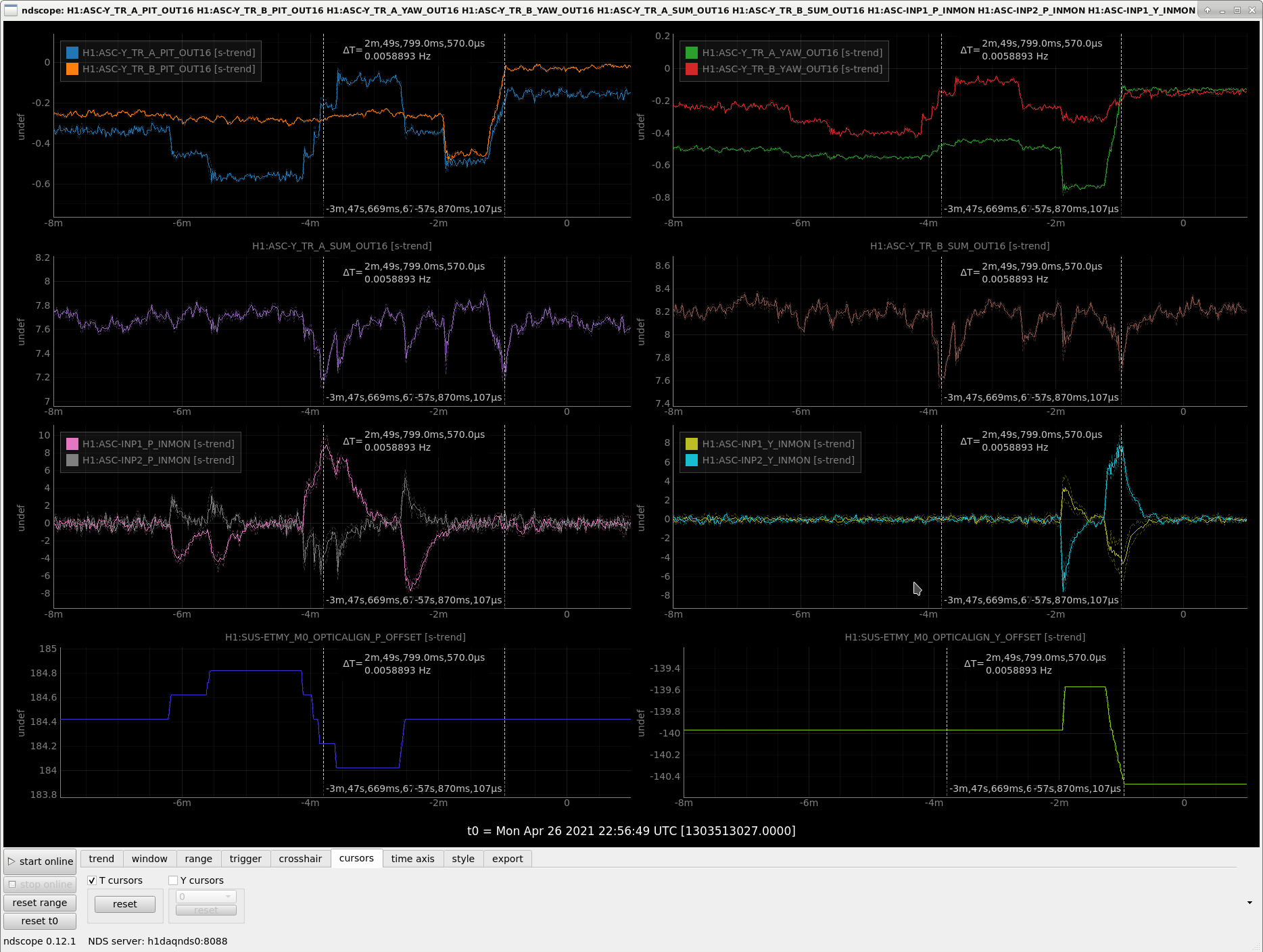
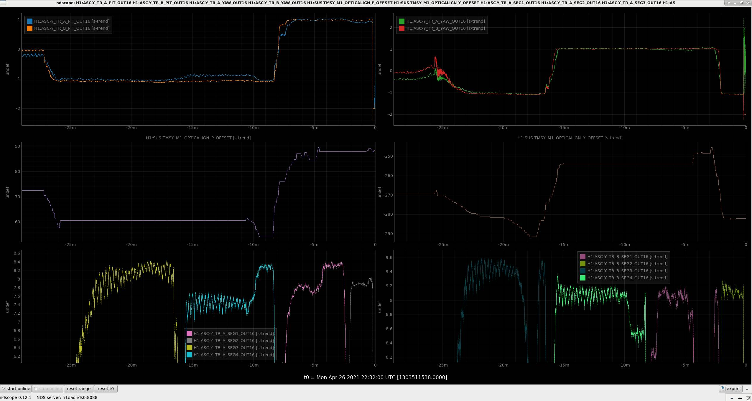
First, I checked that indeed we are not clipping on anything obvious. With the Yarm locked on IR, but no WFS, I over-rode the trigger matrix so that the guardian wouldn't think we lost lock unneccessarily, and moved the TMS in several different offsets: Roll, Trans, Vert, Pit, Yaw. The first screenshot shows a snapshot of this. I don't have calibrations for the R, V, T degrees of freedom, but pit and yaw I was moving between 5-10 urad.
- At Anamaria's suggestion, I first moved Roll and the power on the QPDs went up a little bit as I approached what the pit and yaw outputs reported as the edges of the QPD. This seemed consistent with how things often look when you're approaching the edge of a PD. Certainly I didn't suddenly lose power on either the A or the B QPD (except when I really did lose lock, around -25 mins). So, no evidence of clipping.
- I moved Trans, then Vert. Neither gave any response on the sum of either the A or the B QPD. Good.
- I moved Pit, then Yaw. Both of those had similar behavior as the Roll moves - power increased in a way that looks like what happens when you approach the edge of a PD. No loss of sum power.
- So, no evidence of clipping from this test.
Next up, Keita suggested putting all the light onto individual quadrants of the two QPDs, to check that they all respond at DC with about the same levels of signal. Indeed they do, in that all 4 A quadrants respond about the same as eachother, and all the B quadrants respond about the same as eachother. There is a small difference in the total values on A vs. B, but it's not big (9.1 cts on B vs. 8.3 cts on A), and that isn't so surprising given they have slightly different beam paths. I note that when going from segment to segment, Pit and Yaw for the B QPD seemed more well aligned to the TMS slider pit and yaw. For the A QPD, I needed to also touch up the other slider to get nicely optimized on a given segment. But, overall, moving the Pit slider moved move things in pit, and moving the yaw slider moved things in yaw. The second screenshot shows this time, including the TMS sliders.
|
Counts at H1:ASC-Y_TR_[A,B]_SEG[1-4]_OUT16 |
A | B |
| Seg 1 | 8.3 | 9.1 |
| Seg 2 | more than 8.0 (lost lock before fully optimized) | 9.1 |
| Seg 3 | 8.2 | 9.4 |
| Seg 4 | 8.3 | 9.1 |
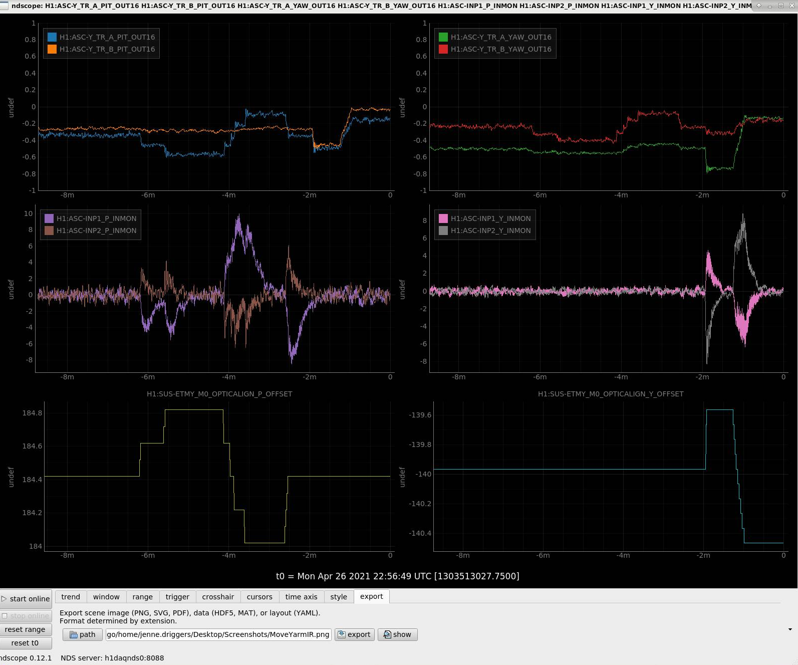
Finally, I engaged the Input Align (Yarm version) via the ALIGN IFO guardian, so that when I moved a cavity mirror, the input laser would follow along. I then moved ETMY in both pitch and yaw. This time (moving the cavity axis, rather than the TMS), the QPDs do not respond in a sensible way; pitch is seen as yaw, yaw as a mixture - it's a mess. This is what has been seen before, so is just a reconfirmation of that. The final screenshot shows these moves.
Since there does not seem to be clipping on the way to the TMS IR QPDs, and they respond as you'd expect when you move the QPDs relative to the beam (by moving the TMS), and each of the QPDs' 4 quadrants are well balanced, we don't think there are any in-vac or electronics problems. But, we still have the mysterious QPD response to cavity moves, which is no good.
PeterF brought up today something that we'd been trying a bit last week - chosing not to use the QPDs to blend CHARD. Anamaria notes that LLO does not do any blending, although this means that they do see more of the HAM response in the error signals, which is why they do HAM1 feedforward to CHARD. So, perhaps we should revisit the idea of not blending CHARD pitch (just as we have not been blending CHARD yaw at all the last few weeks), and see if we can figure out why we were losing lock when trying that.
I forgot to say yesterday - I removed the lowpasses from the sum channel that normalizes the pit and yaw signals. This lowpass was removed from all 4 IR transmon QPDs. Keita pointed out that for something like an oplev / QPD, we don't want that kind of lowpass.
No conclusion here, but these are things I looked at so far.
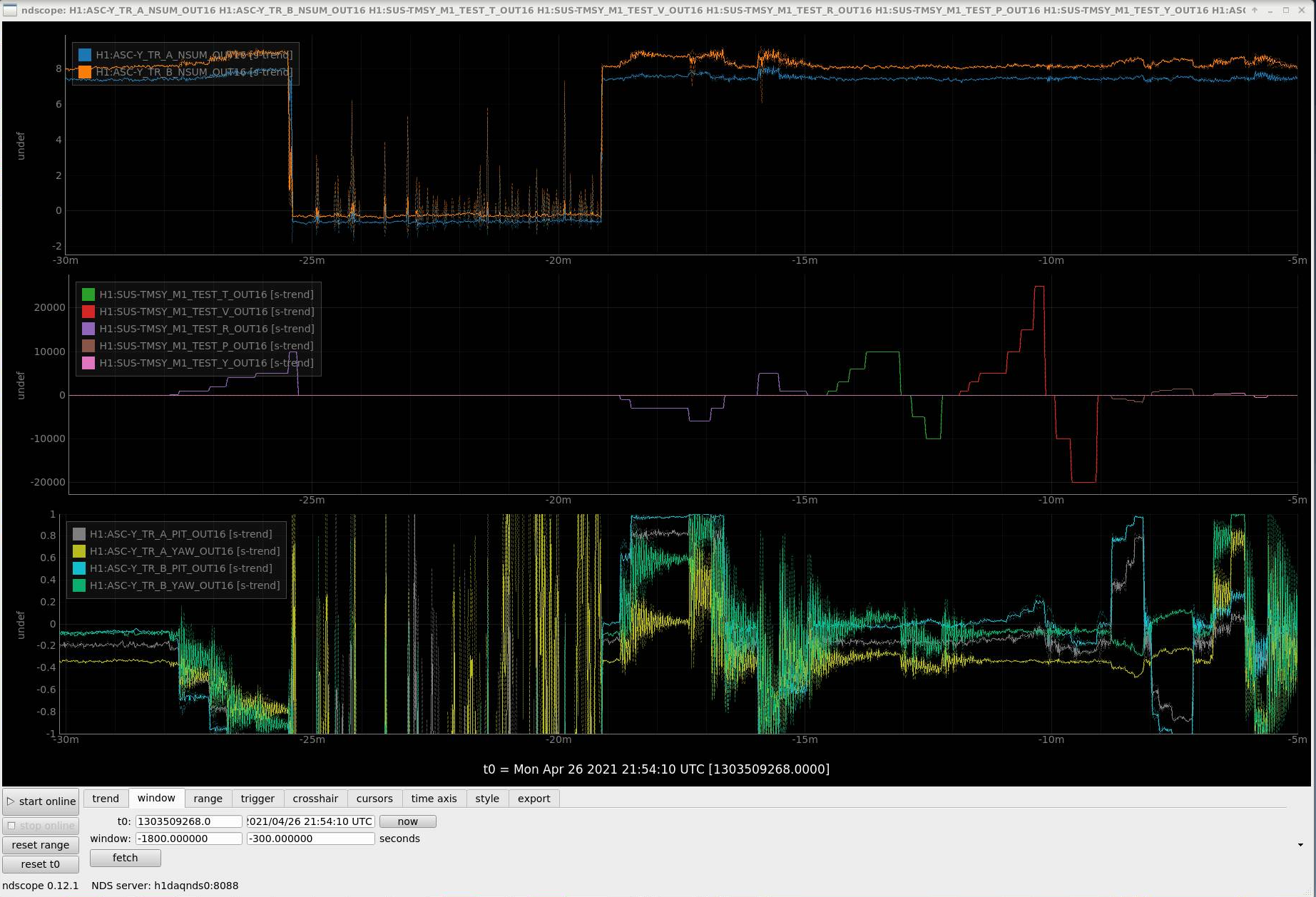
1: No sign of big clipping when moving ETM either. (1st attachment)
I checked if there was a sign of clipping while Jenne moved ETM, and found none. There was some initial power dips right after the mirror was moved, but as ASC followed up the power was restored.
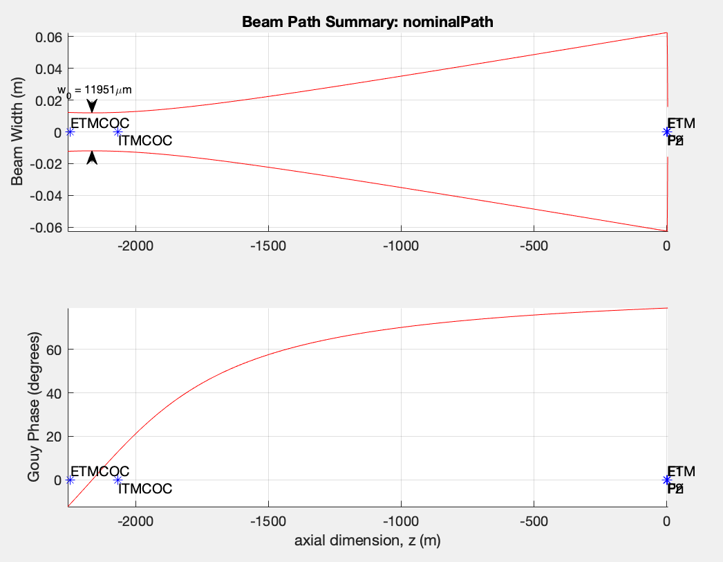
2: What's the difference? Gouy phase. (2nd attachment)
When you move ETM, the cavity mode rotates around the center of curvature of ITM. OTOH, when you move TMS, it's (almost) an equivalent of beam rotation around the Primary mirror of the telescope.
It's hard to see in the 2nd attachment due to horizontal scale, but the Gouy phase difference between ITM center of curvature and the primary mirror is ~66 degrees.
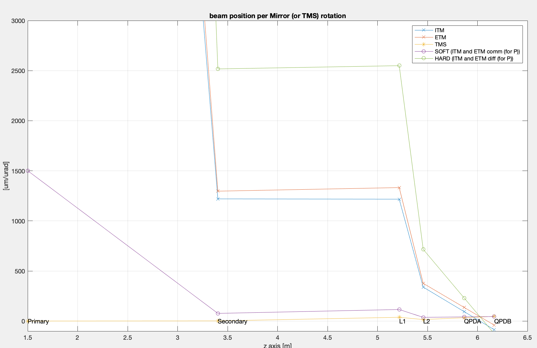
3: What's the difference? Beam displacement per optic rotation on telescope and relay optics. (3rd attachment)
1urad of rotation of ETM and 1urad of rotation of TMS produce similar beam displacement on the QPDs, the difference is the sign of the signals (differential for ETM, common for TMS).
Despite that, there's a huge difference in the beam spot displacement telescope and relay optics. Displacement per radian on the primary mirror caused by ETM rotation is about 5 orders of magnitude larger than that caused by TMS rotation, it's reduced to a factor of 600 (on the secondary), 38 (1st lens on the sled) and 25 (2nd lens).
4: No conclusion yet.
Based on 2: and 3: there might be a room for conspiracy type scenario that includes missentering on lens/curved mirror and/or clipping (though there doesn't seem to be much clipping if at all).
(BTW I found that the distance of the QPD sled from the telescope is maybe 70cm larger than the original design (https://dcc.ligo.org/T0900385) where the distance between the secondary on the telescope and the first lens on the sled is 1094mm~43.2". Just by looking at the TransMon drawings (e.g. D1002460), knowing that the TMS ISC breadboard is 30"x30", there's no way that the distance from the secondary to the 1st lens is as short as 43". This is not a big deal, Rayleigh range is larger than 10 meters here, resulting in 87 degrees of Gouy phase difference between QPDA and QPDB rather than 90.)