May 17 (Camiila, Keita): B-path off-sled KTP wedge (B:P1) angle was set.
1. We used the beam injected from the OFI direction (B:M4) back into SFI2 that we set up last week (alog 58931), which was set to be level with the OPO platform.
2. We first removed B:P1 and the steering mirror B:M2 from the beam path to direct the beam off of the OPO platform and measured the beam height from the optics table at the position about 25" or so away from the OPO SUS edge using a ruler and a sensor card with a hole. It was about 1/32" higher than 4".
3. Ryan at UF confirmed that we're supposed to use 0.75"-1" adaptor for the KTP wedge, so we used a LH 1" Siskiyou mount via 0.75"-1" adaptor. We placed the wedge roughly in place and adjusted the roll angle so the beam height became ~1/32" heigher than 4" over the same distance as 2. above.
4. We set the PIT angle by looking at the height of the AR reflection using IR sensitive camera and setting it within 1/64" of the nominal 2.5".
5. We fixed the wedge position as per D1500302. Wedge itself is on the 3rd screw hole colum from the edge of the SFI2 sled, and the wedge was adjusted sideways so that the beam is well centered.
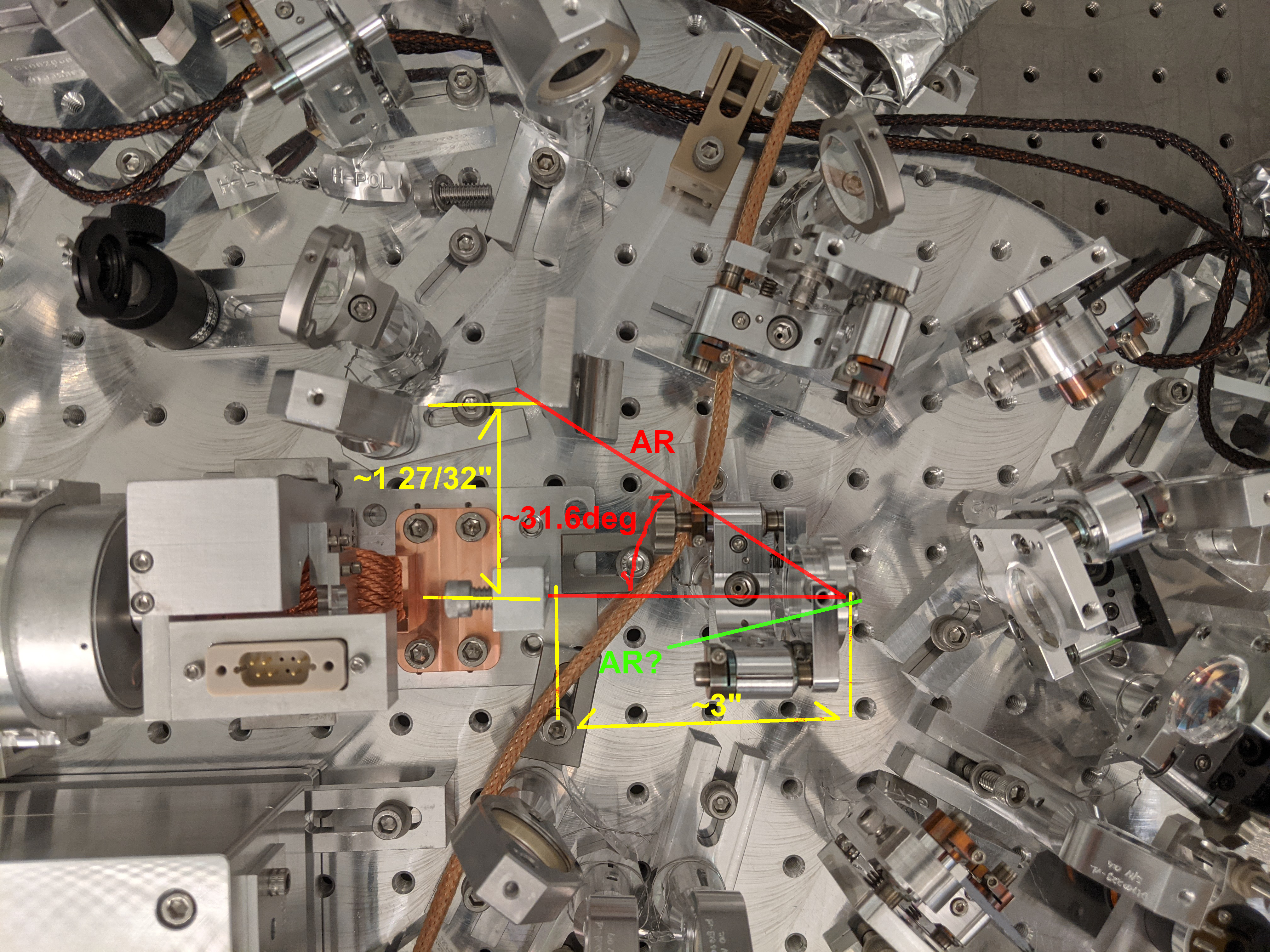
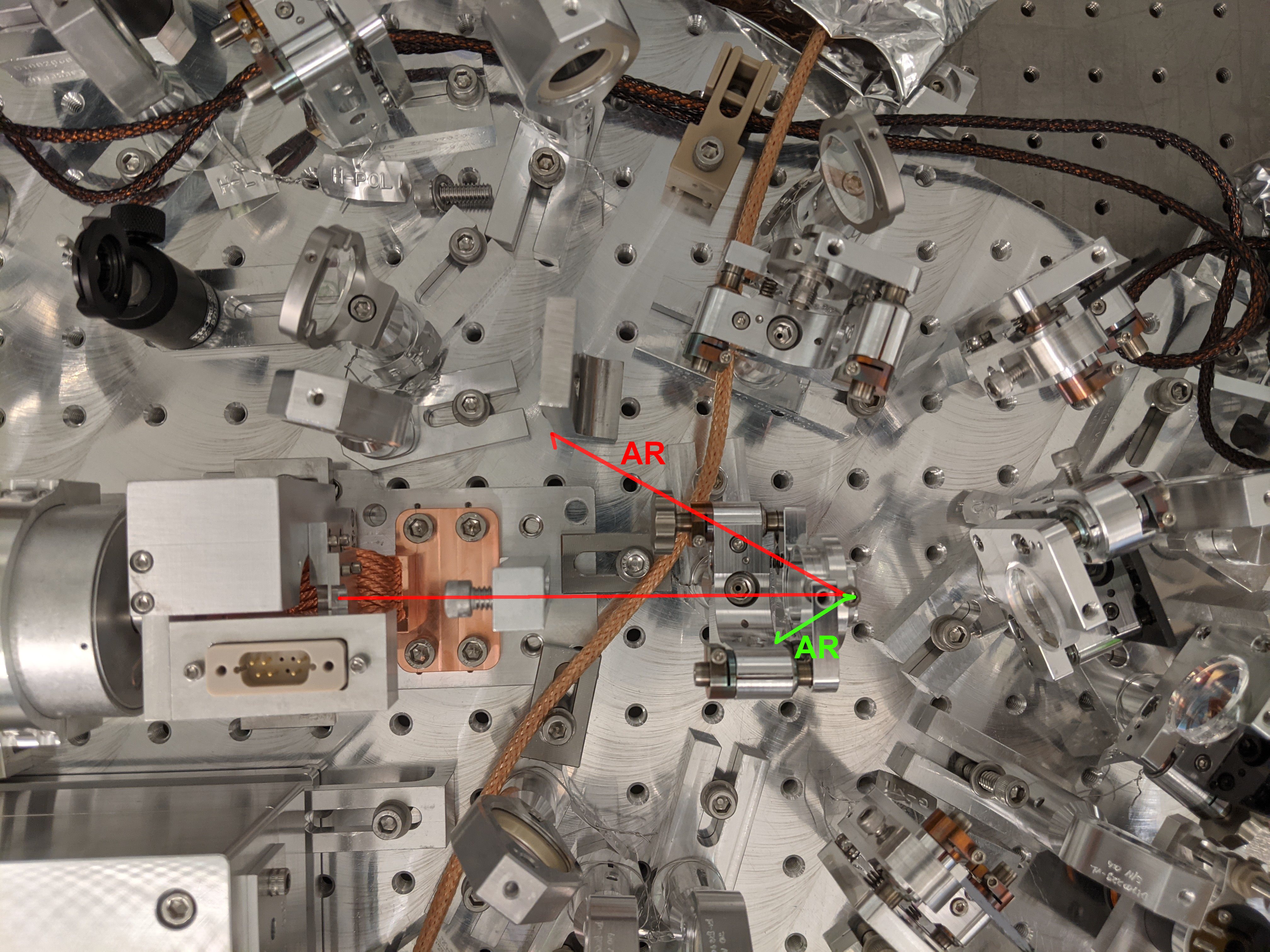
6. Set the YAW angle of the wedge so the AR reflection and the main beam forms ~31.6deg angle (red line in the attached). I used two dogs placed vertically to aid the alignment.
7. I didn't check if the AR reflection from the back surface (green) clears the Siskiyou. Will check tomorrow.
May 18: Slow day (Camilla, Keita)
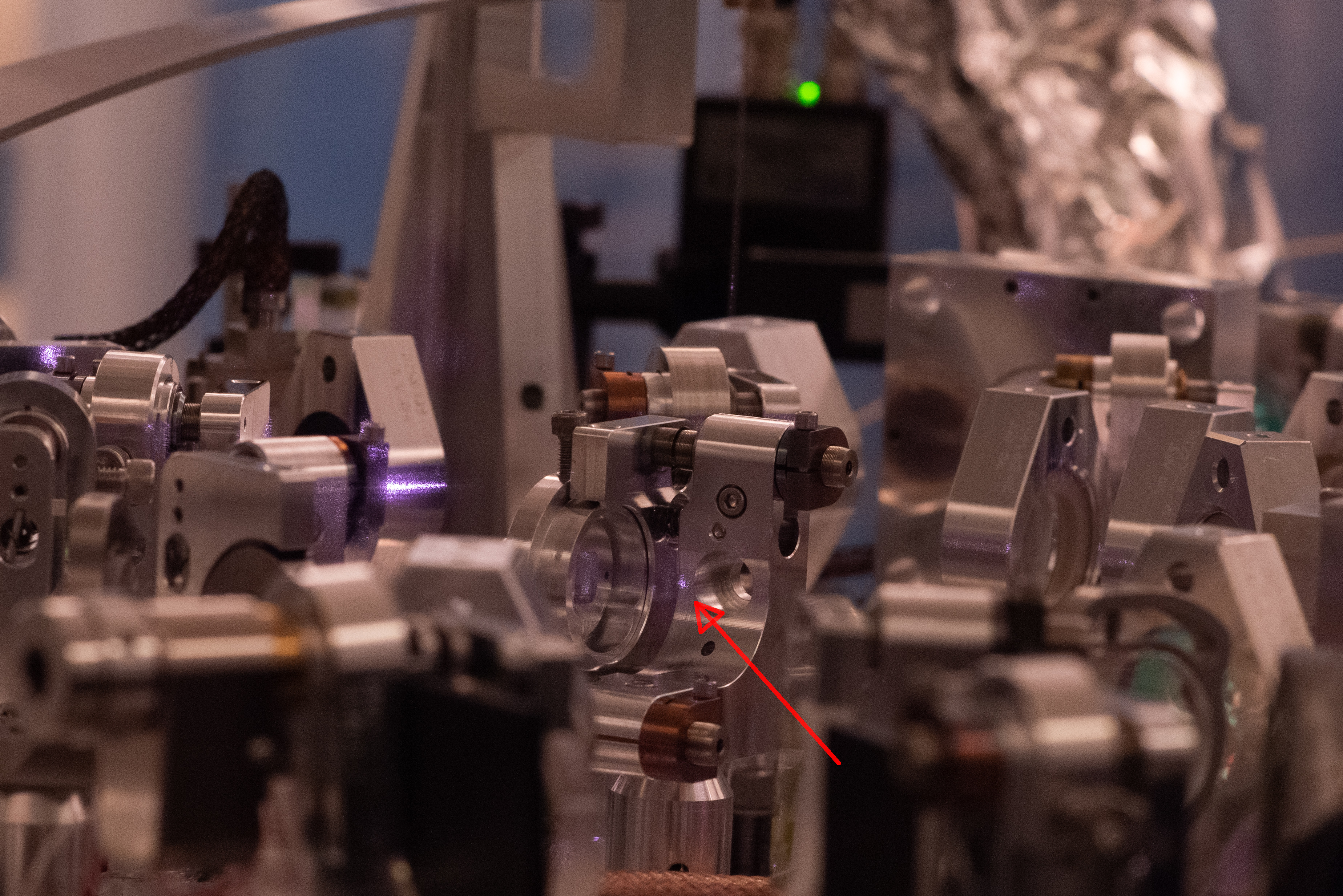
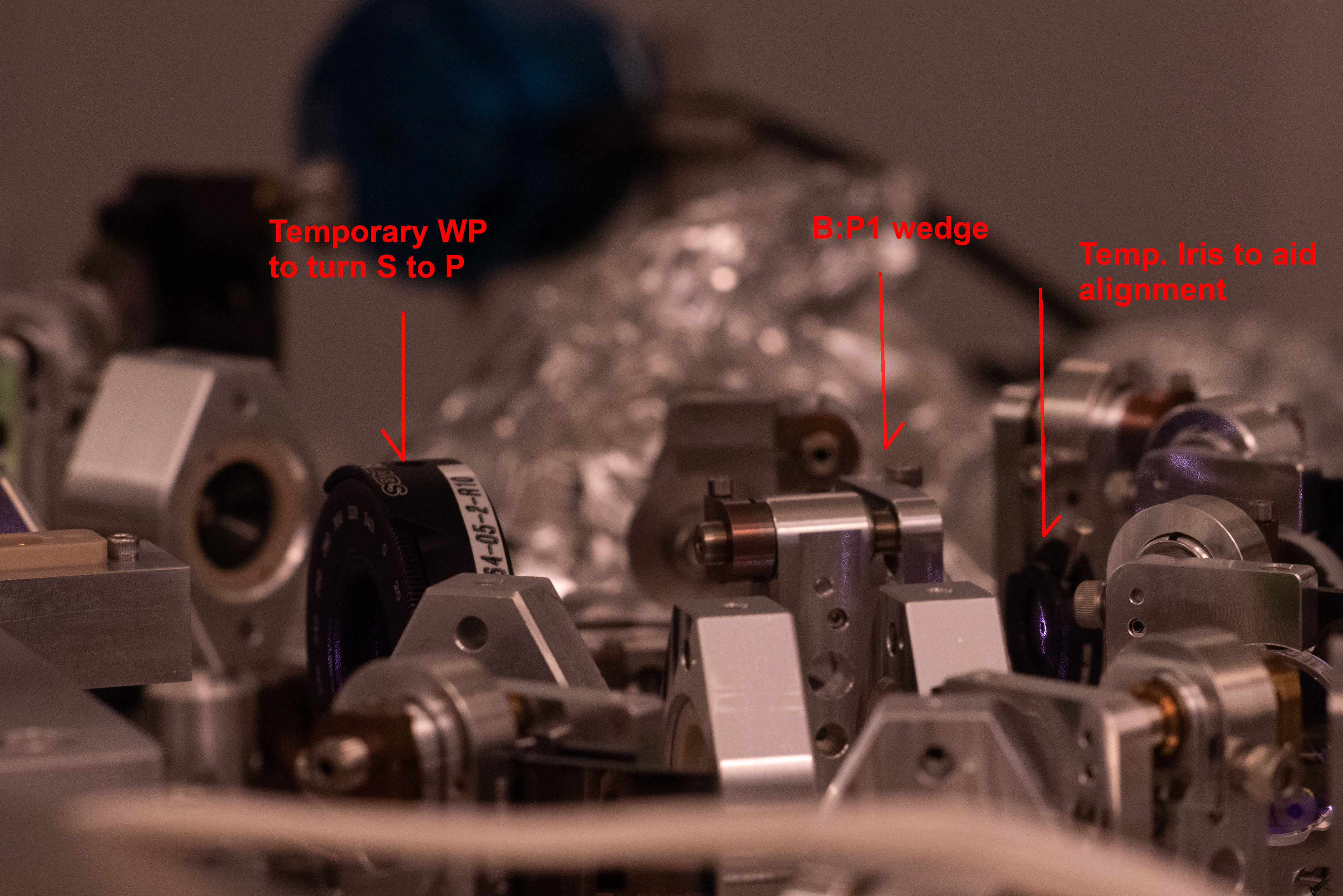
When we inject S-pol light from the OFI side to SFI2, with the angle of B:P1 wedge set correctly, AR reflection from the back side of B:P1 hits the 1" Siskiyou mount for B:P1. See the first picture showing the AR beam spot on the Siskiyou. Second picture shows the rough beam path, and the green line shows you the AR path we're talking about. We'll wait for an input from UF.
We placed a temporary waveplate between SFI2 and B:P1 so that most of the power that falls on the wedge becomes P-pol, and installed a temporary iris as an alignment helper (3rd picture).
We then disconnected the IR fiber from B path launcher and reconnected it to the OPO injection fiber. We locked OPO but was distracted by how unstable the PDH error point was (seemingly lots of RFAM that fluctuates).
May 19: Continuing B path (Georgia, Keita)
OPO PDH nastiness was mostly coming from mode hopping. We changed the crystal temperature of NPRO and the error signal became nicer.
We locked OPO and roughly aligned the beam into SFI2. The process was easy. We used B:M1 to steer the beam so that the beam hit the center of the temporary iris we installed yesterday between B:P1 and B:M2. Then we used B:M2 to steer the beam to hit the input side aperture on SFI2. At this point some beam went through the output side aperture and came out of the back of the now-disconnected fiber coupler (that is used for injecting from OFI side).
We installed B:L1 at roughly the right location, moved it sideways so the beam hits the center of the temporary iris, and again the beam went through SFI2 and came out of the fiber coupler.
We removed B:M2 to bring the beam out on the optics table in preparation for the mode shape measurement.
May 20: Mode shape measurement downstream of B:L1 (Georgia, Keita)
Looks poor, some adjustment is necessary.
Measurement Details: Locked OPO to IR beam injection from F:COL1, retroreflected the OPO transmission using a flat mirror in the FC path external of OPO platform (the same mirror we used for retroreflection), removed B:M2 to bring the beam out to the optics table and measured the beam size by NanoScan with B:L1 lens set at the nominal location, which should be 8.75" away from the TFP of SFI1 if I interpret Lee's diagram correctly. We also measured the beam size w/o the lens as sanity check. Both are consistent with each other (i.e. the ROC of the lens is very close to nominal 350mm).
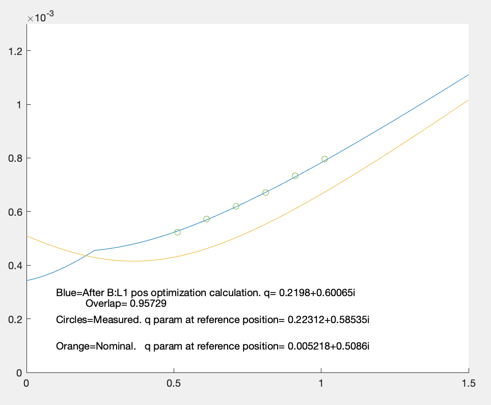
With the measured data, even if we move B:L1 lens, the overlap with the ideal mode will only go as high as ~96%. This part of the path doesn't have to match Lee's model exactly (the only important things should be matching with FC, matching with IFO and that the beam size is OK for SFIs) but I don't understand why it's off in the first place. Maybe I'm missing something.
1st attachment shows measured data points (circles) for PIT and ideal beam shape (orange). Y axis is the beam radius in meters, X is the distance from TFP on SFI1. Blue line is not just a fit of the measured, the lens position is also optimized for the best overlap. Not much change between optimized (95.73%) and non-optimized (95.71%).
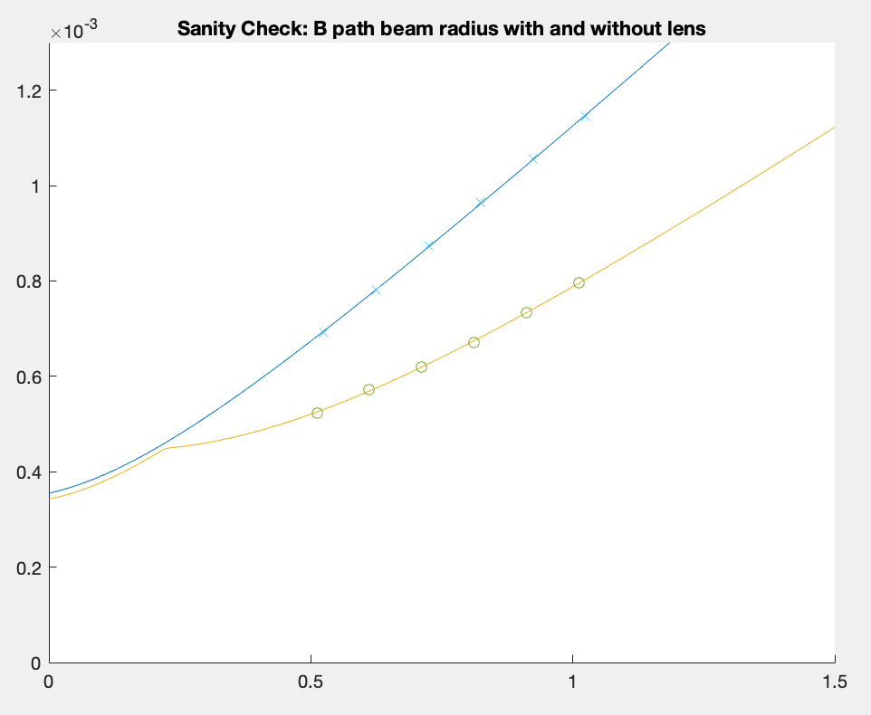
2nd attachment shows measured data points with and without the lens. Assuming that the lens' ROC of 350mm is correct, the overlap between the two is 99.9%, which just means that the measurement isn't a fluke.
3rd attachment contains PIT and YAW data.