Jun 07, H path continued, very limited success.
Light coming out of fiber collimator:
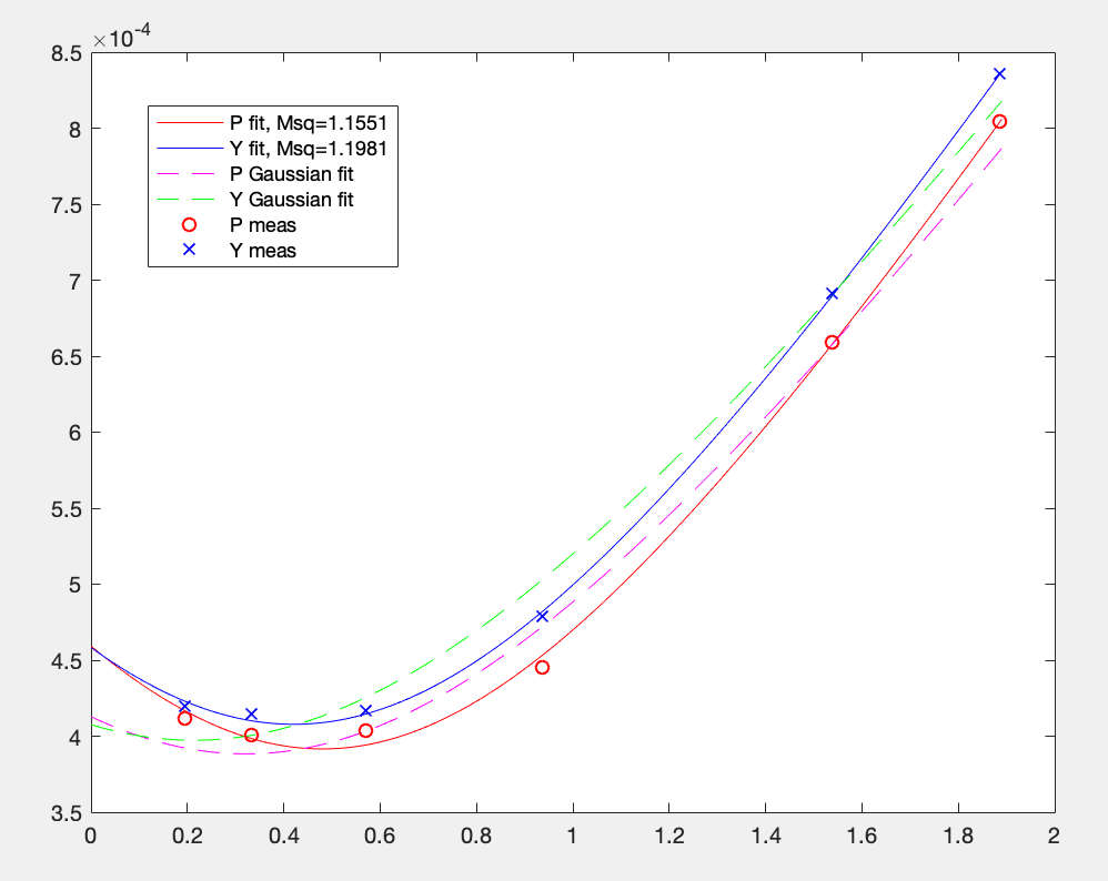
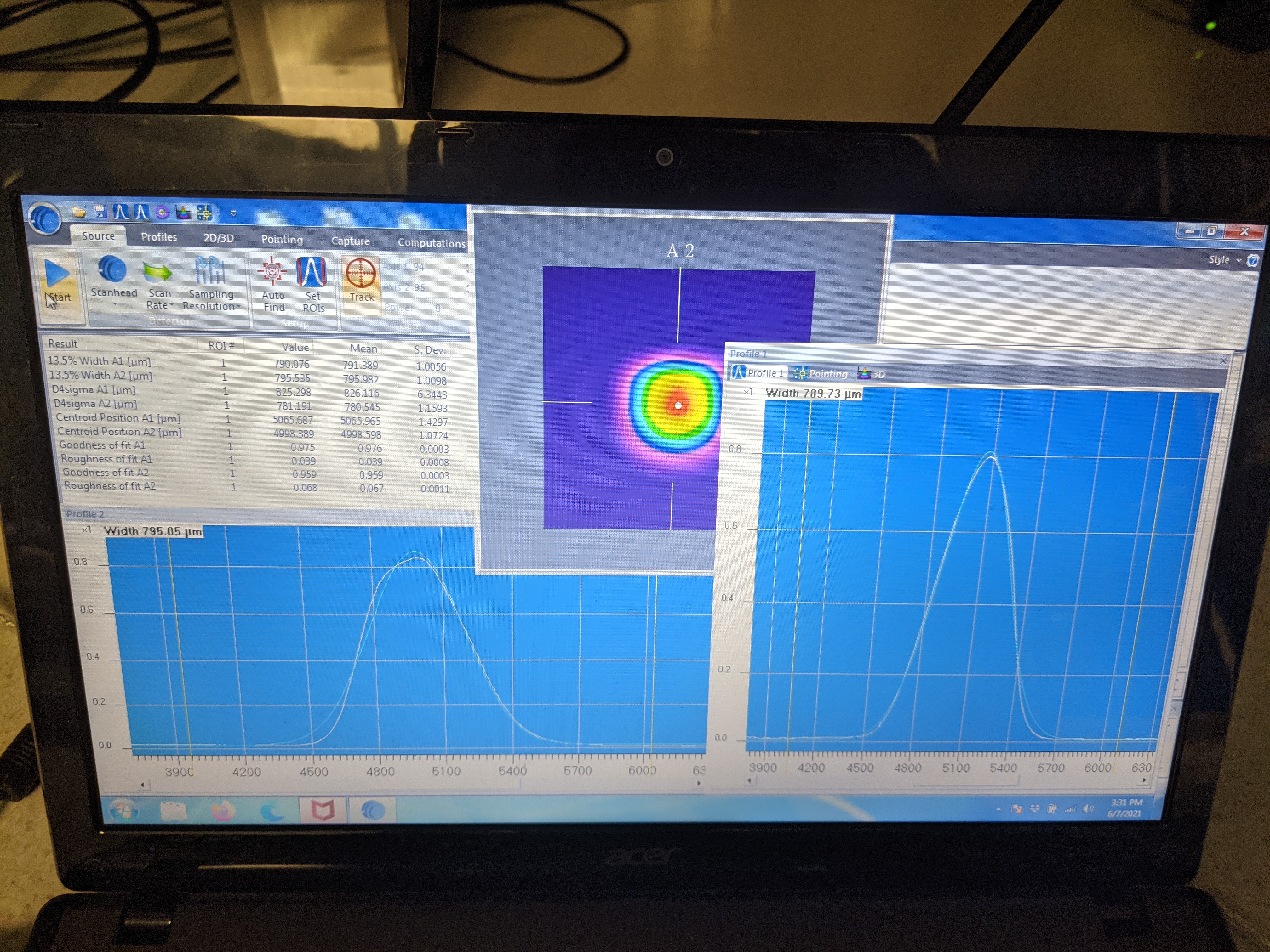
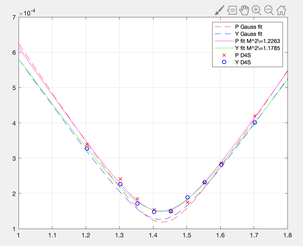
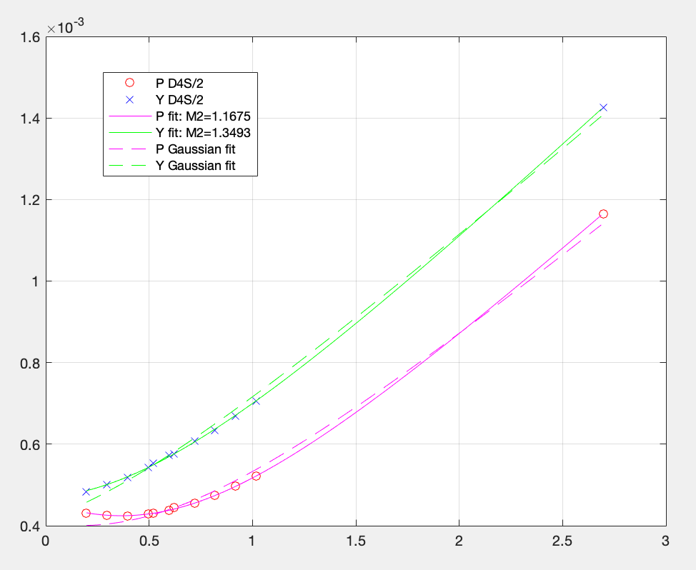
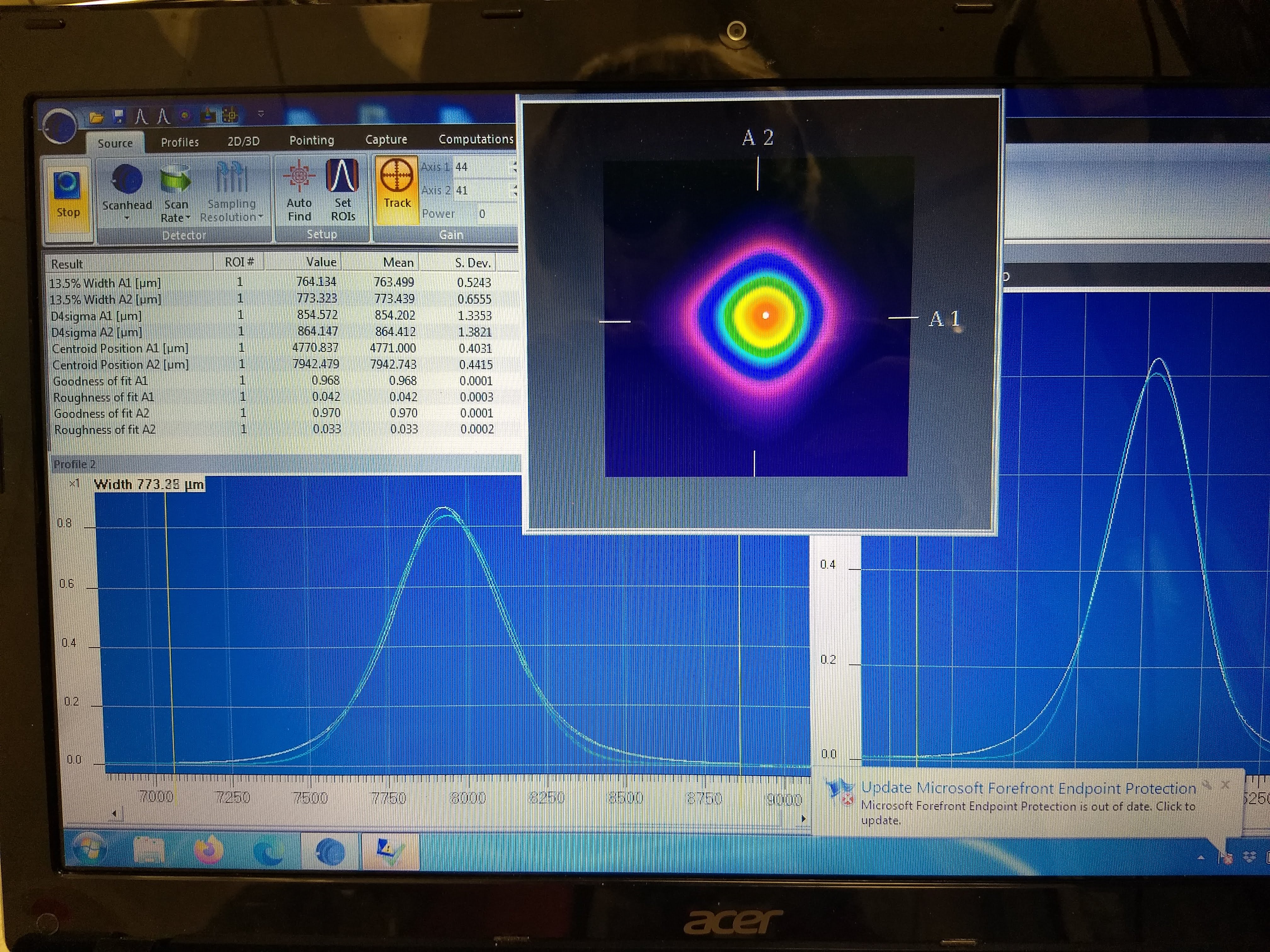
It looks OK, not ugly at around the peak (1st attachment, this is ~1.89m away from the launcher) though it's not like nice and round/elliptical. Used scanner at different locations and reading D4S width (attachment 2, y axis is radius, also the script/data is attached). Though only sparsely sampled due to space limitation, if I calculate M2 from this it would be ~1.16 (P) and ~1.20 (Y). Well, not the end of the world.
Disconnected the fiber from the collimator to clean the fiber end using the specified fiber cleaner (just to see if there's something obvious), reconnected, no meaningful change.
Clipping:
Nothing obvious was found. I changed H:M1-H:M2 path slightly in YAW to make the beam go farther away from H:L3 (by simply turning H:M1 without moving lenses) and then used H:M2 and H:M3 to get the green back on top of IR.
As of now,
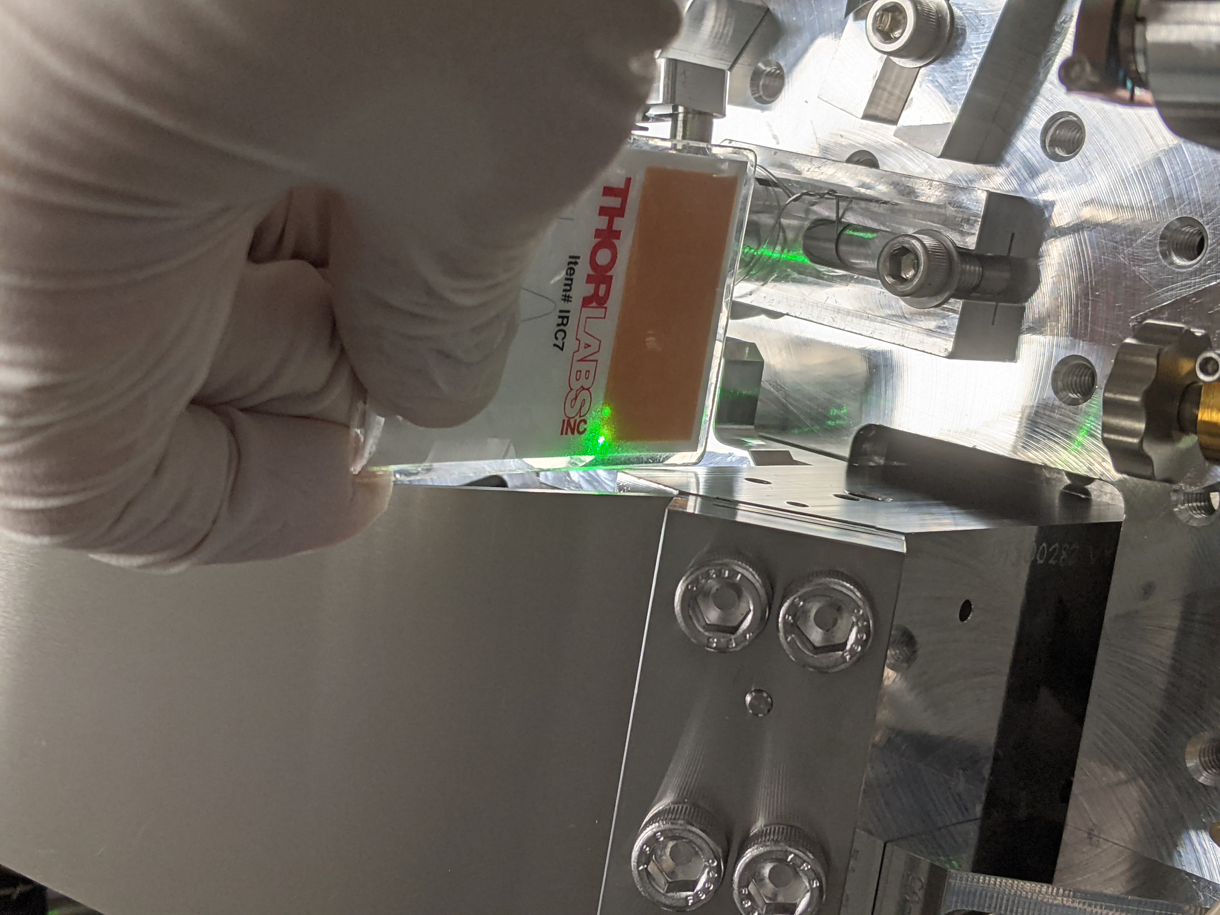
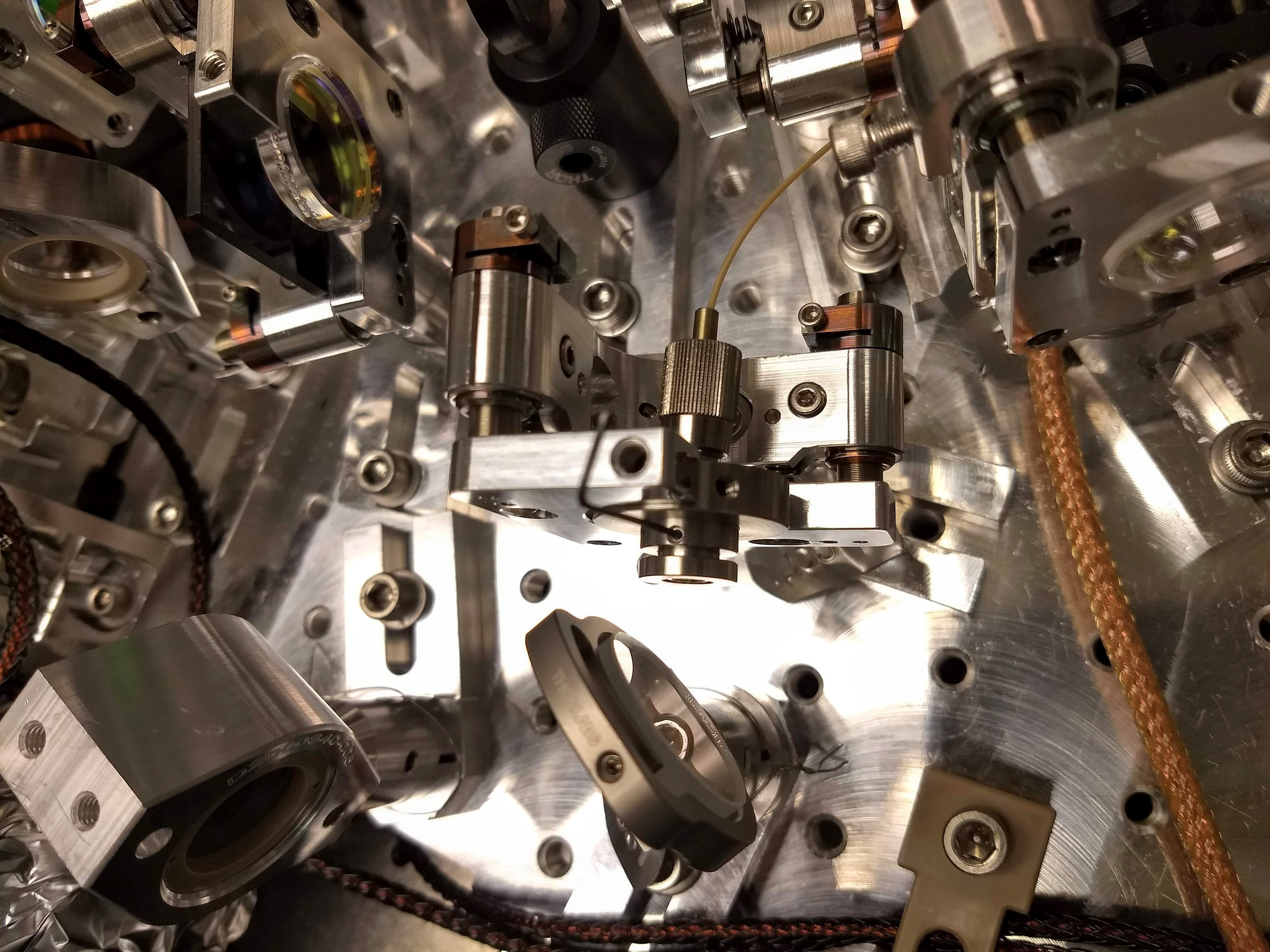
Base of one SUS blade is ~4mm away from H:M1-H:M2 path (3rd attachment).
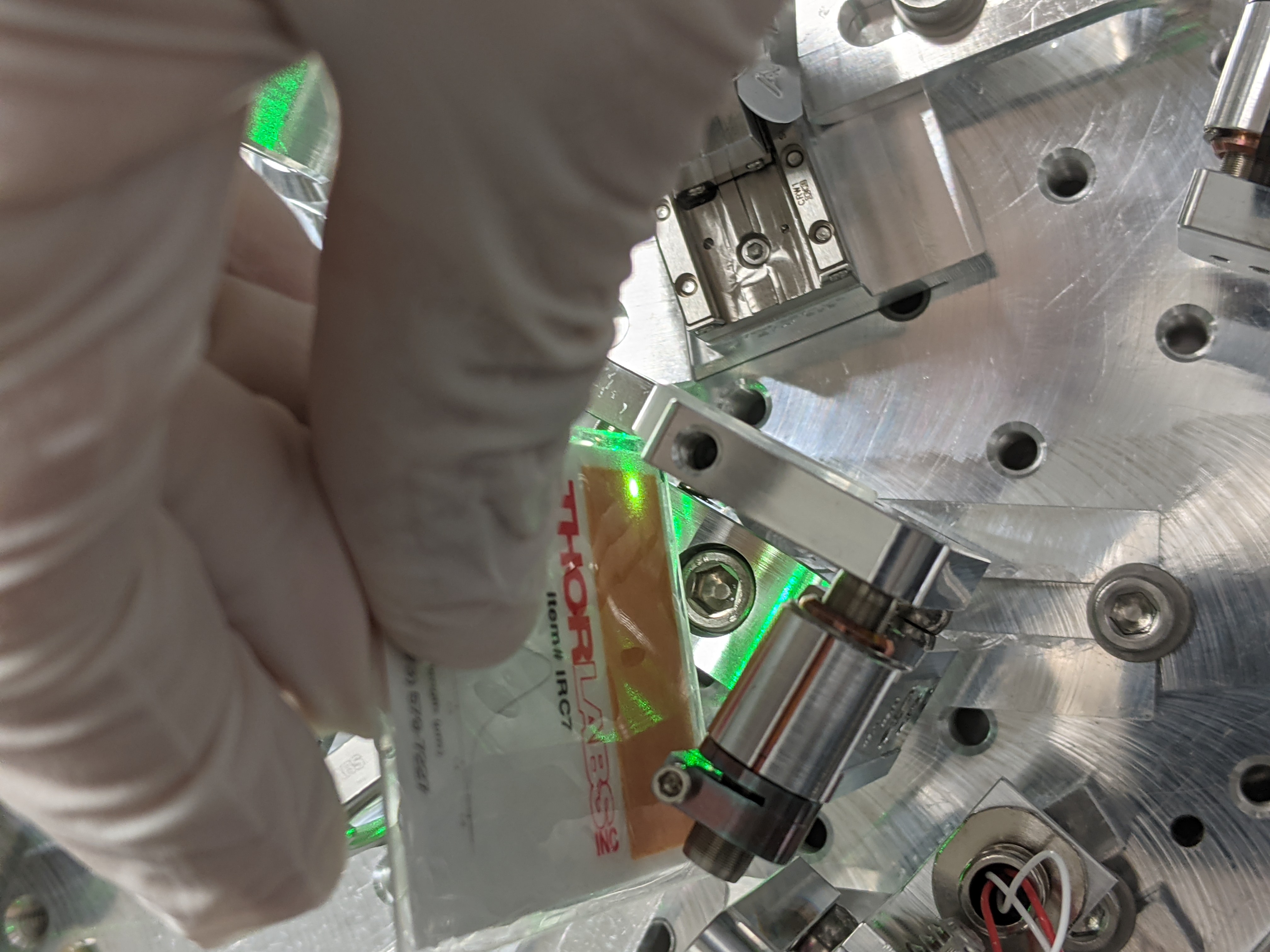
Dichroic edge is ~5mm away from the center of the beam but the beam is bigger there than at the SUS blade base (4th attachment). Same for A:M3.
H:L3 edge is 7 to 8 mm away from H:M1-H:M2 path (5th attachment).
There's no space to insert a mirror for sampling the beam downstream of H:M2.
Beam going to FC:
Arguably the beam profile looks somewhat better than before (6th attachment, see this picture from Camilla's alog for comparison), but not in any meaningful way for matching.
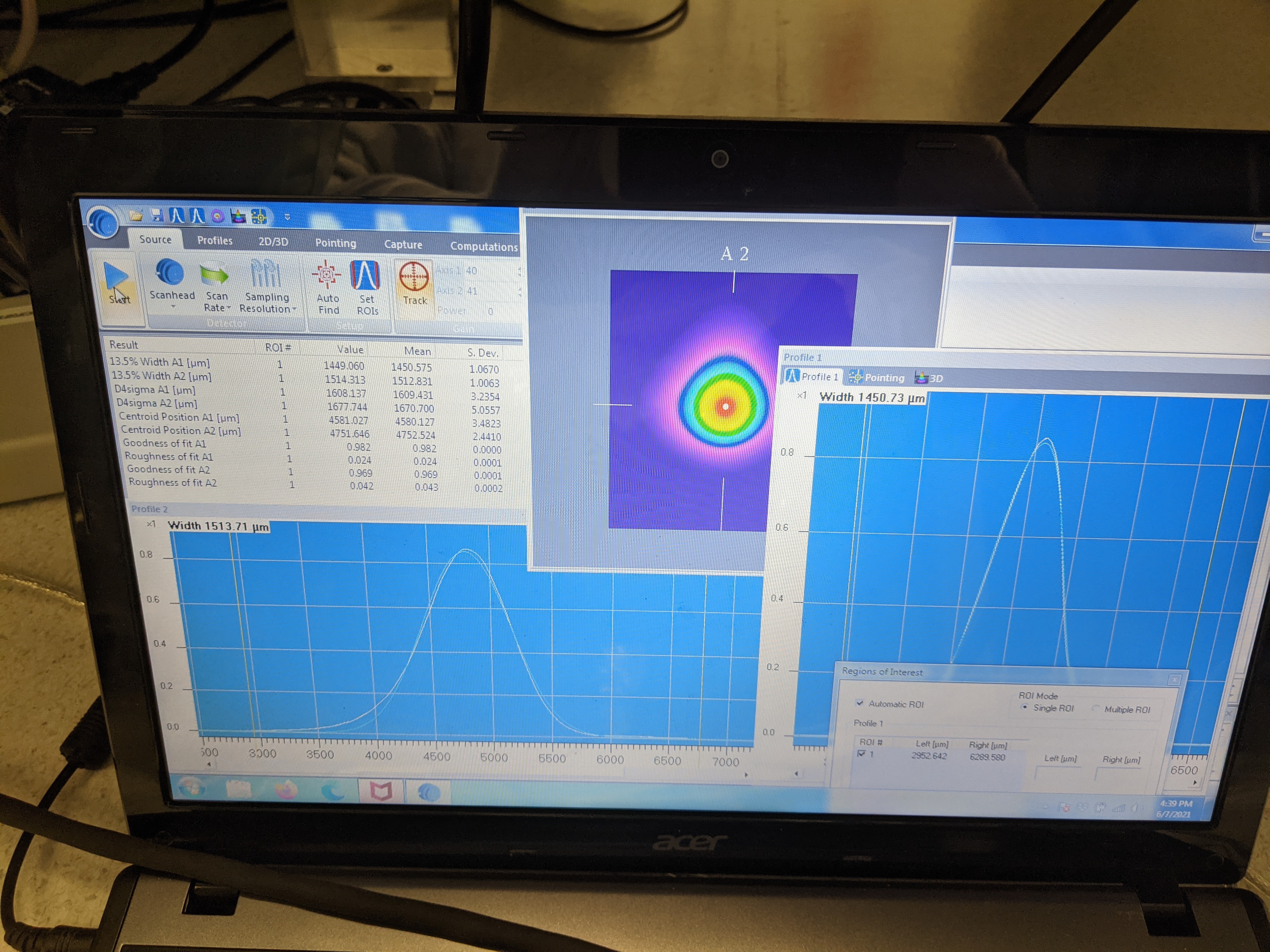
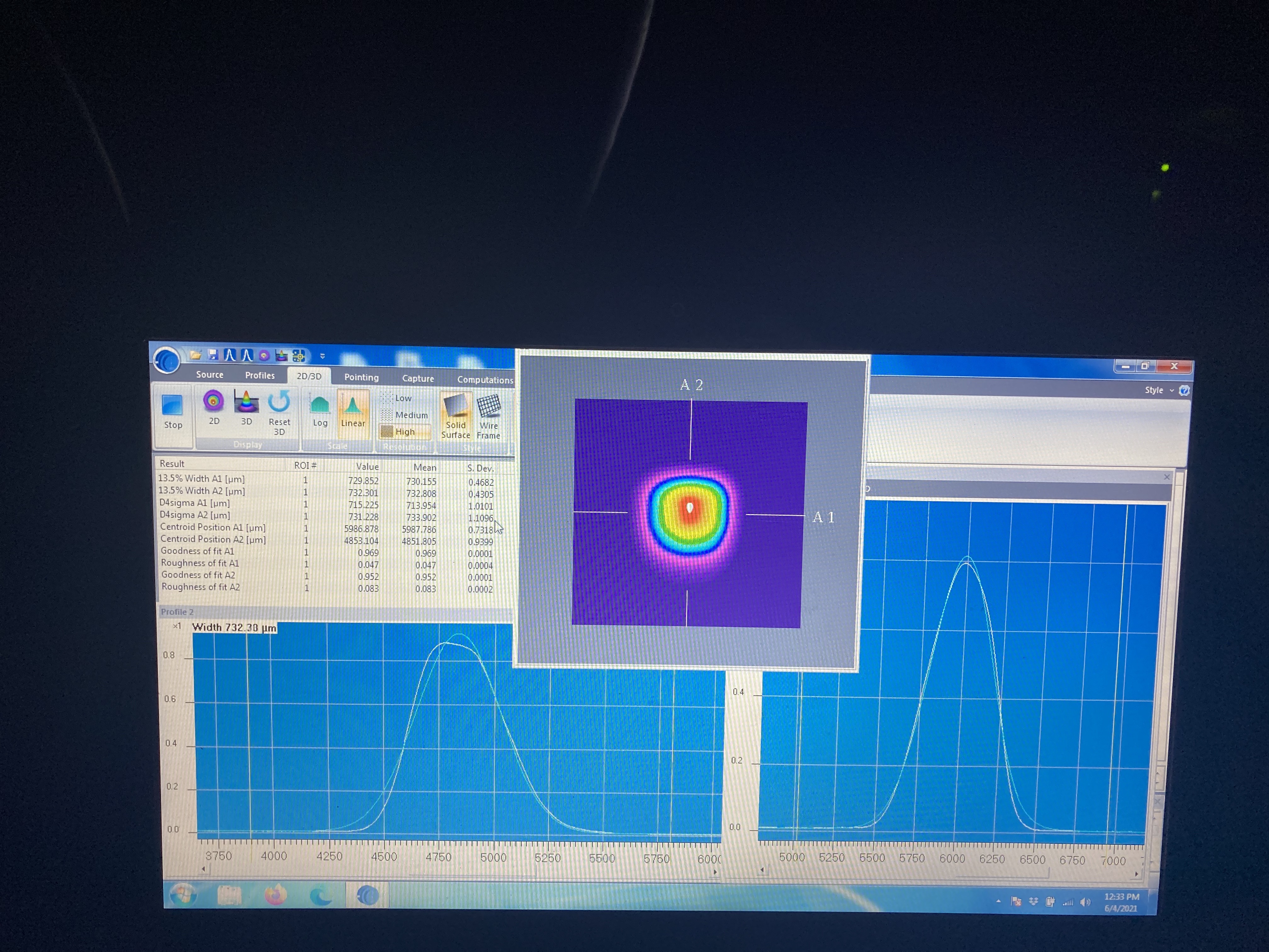
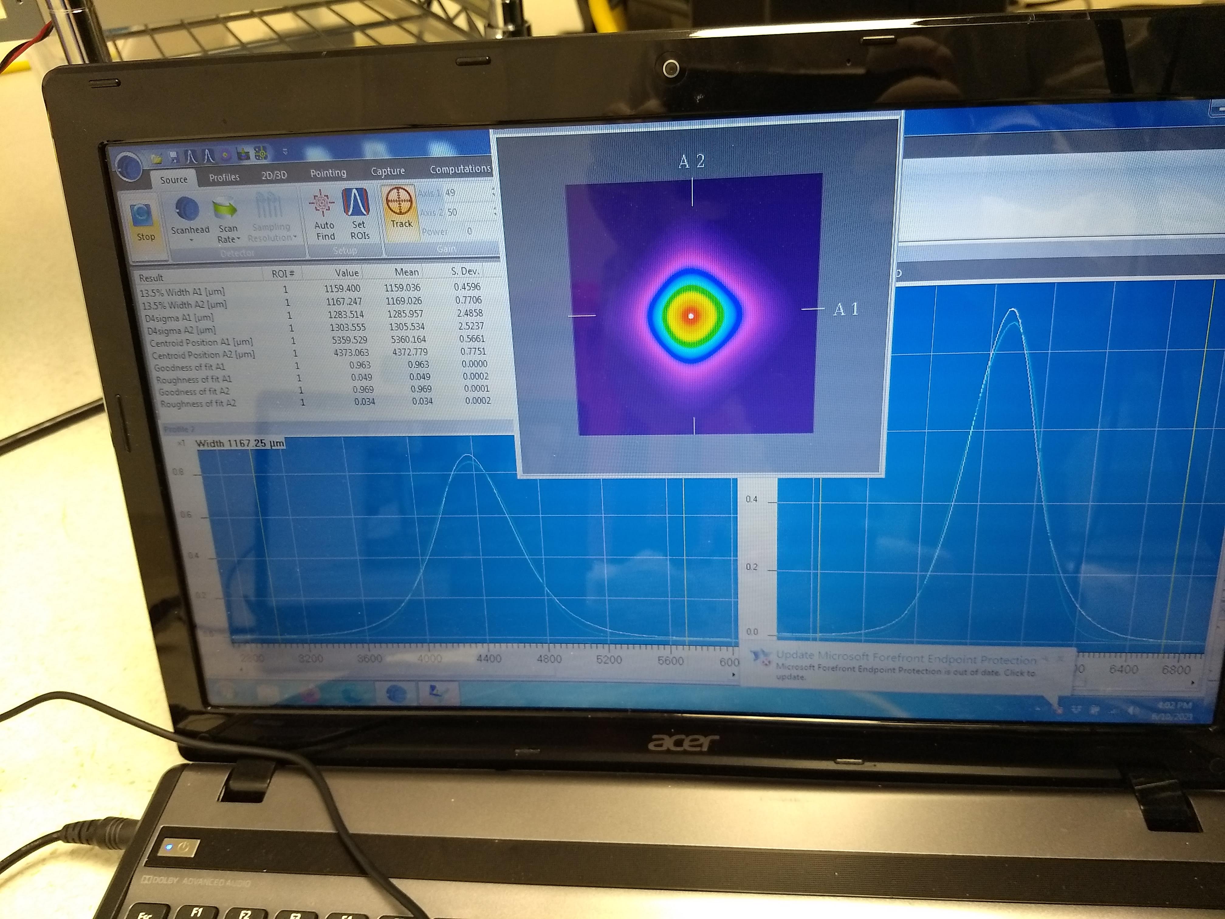
Since the nanoscan was happy to output consistent numbers for D4S width, I used that. 5th attachment shows the scan data, it's still sparsely sampled but it looks that M2 is as large as ~1.2.
Gaussian fit results give us ~94% matching for PIT and YAW, which is somewhat but not much better than before (alog 59123, 91% and 94% using 1/e^2 radius). (However, Camilla's D4S numbers from Friday (alog 59131) gave us ~85 and 88%, so this is an improvement).
Again, unless the lenses can get closer we won't get a better matching. Could replace one of 150mm with 100mm and re-optimize in the model but the question is if that's worth the effort when it turns out that that would give us a better matching.

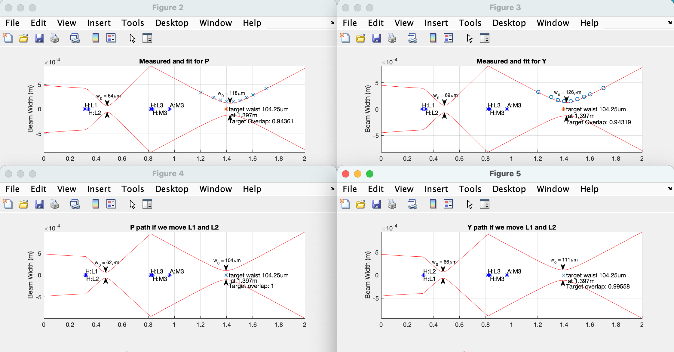
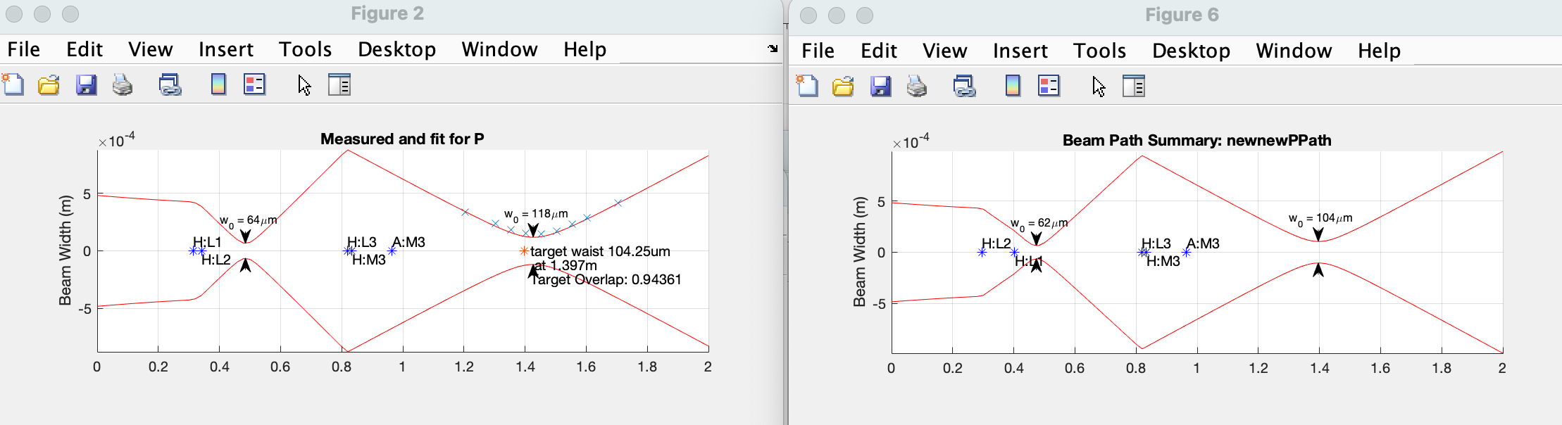
I quickly checked to see what happens when I use 100mm ROC lens for L:H2 and keeping 150mm for L:H1, and it seems to work. Again, is it worth it?
Left is as is, right is after lens swap and optimization where mode overlap is basically 1 (if we pretend that the beam is Gaussian, which it isn't).
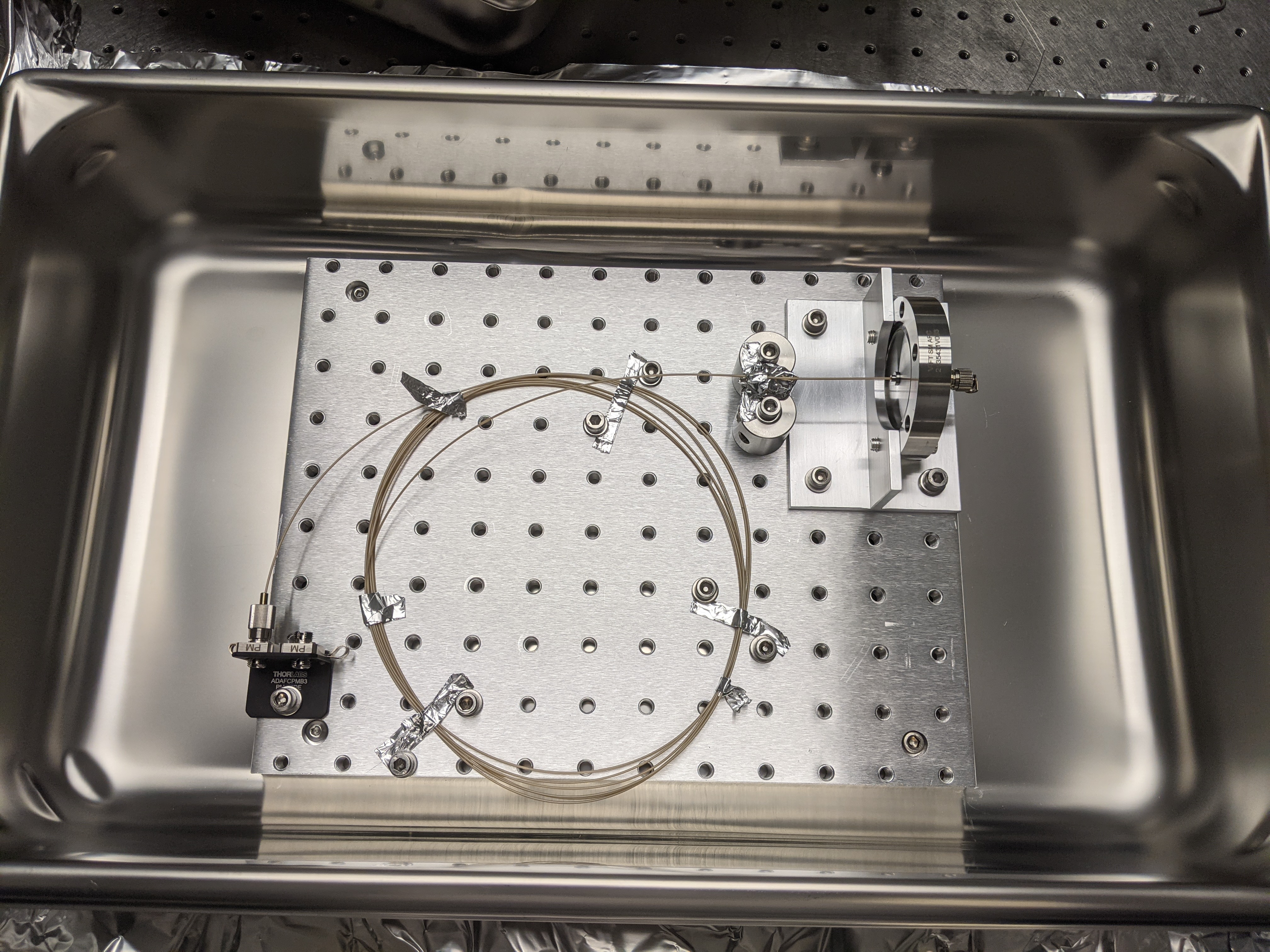
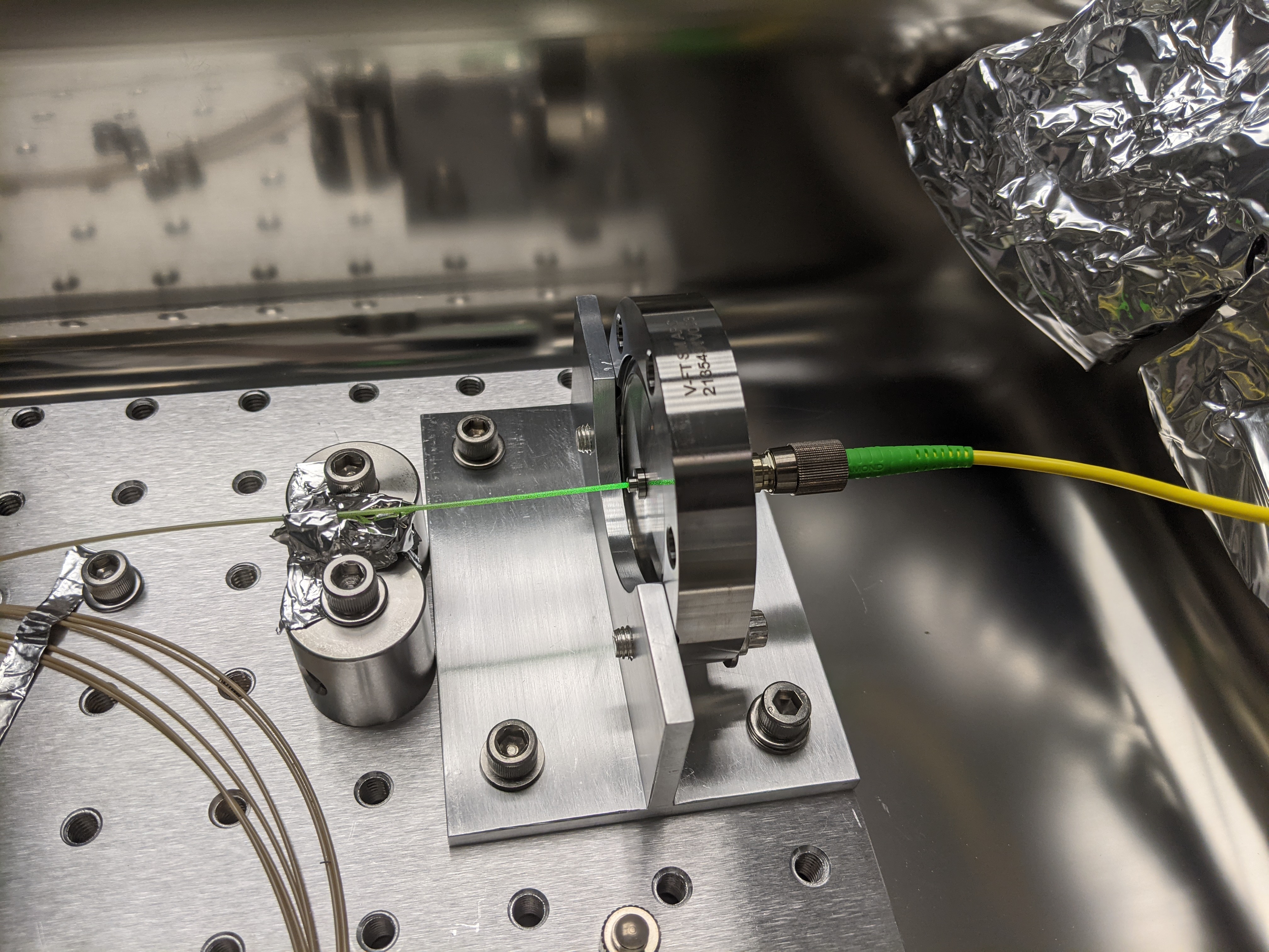
Jun 09, new in-vac Diamond fiber is delivered safely.
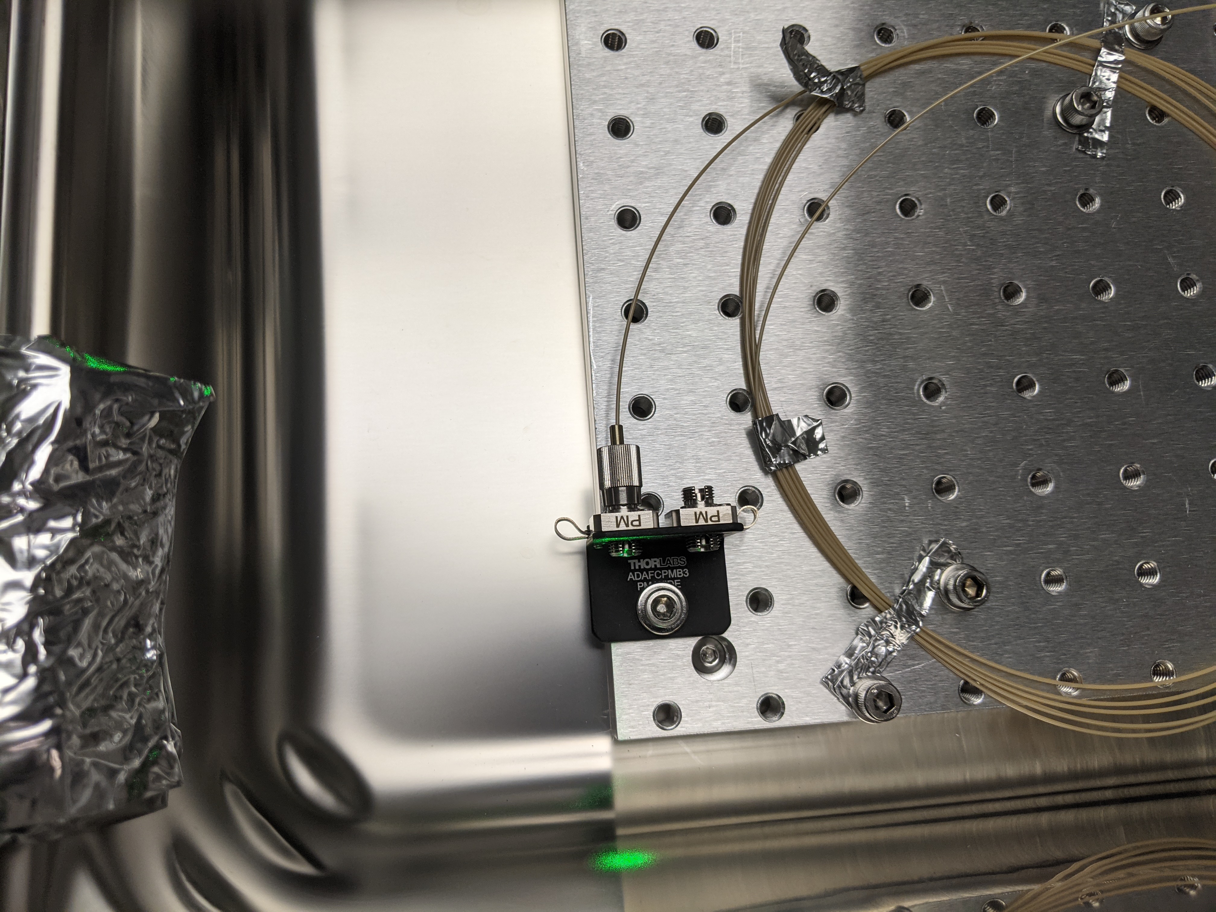
I and Camilla tested the new fiber and it looks to be working. Picture 1 shows the new strain relief method. Before doing anything, we connected the in-air fiber to the feedthrough and the light came out even though the PEEK shell looked somewhat greener than the old fiber (Picture 2, 3). Didn't measure the power coming out.
We then connected the in-vac fiber to the collimator on OPO platform for G path (it was much easier to do so for this collimator than H path collimator) and measured the beam profile of the beam rejected by the polarizer G:POL1 (attachment 4). Again M squared is big (P- data for M2 is believable, Y-data not so much). I'm 99% sure that the connector is fully seated on the collimator. I'll find the measurement by Sheila using the old fiber and make a comparison.
Today I took a look at the H path again
- We were suspicious of the collimator - the beam coming out looks quite square which is weird. Lee mentioned that we should check that the set-screw in the collimator was not clamped down with the lens at an angle. I loosened the screw and gently jostled the lens (see this users guide for a quick diagram of the collimator, and the first attachment for a photo). I don't think there is much wiggle room, and conclude that the collimator is probably fine?
- After this I needed to re-collimate the beam. The second and third attachements show the beam pofiler position and the beam dimensions in the near field. The beam still has a diamond shape. The fourth and fifth attachments show the profiler position and the beam dimensions in the far (ish) field. The beam is diverging a bit, but the collimator is suepr sensitive, so I'm not sure I can do much better.
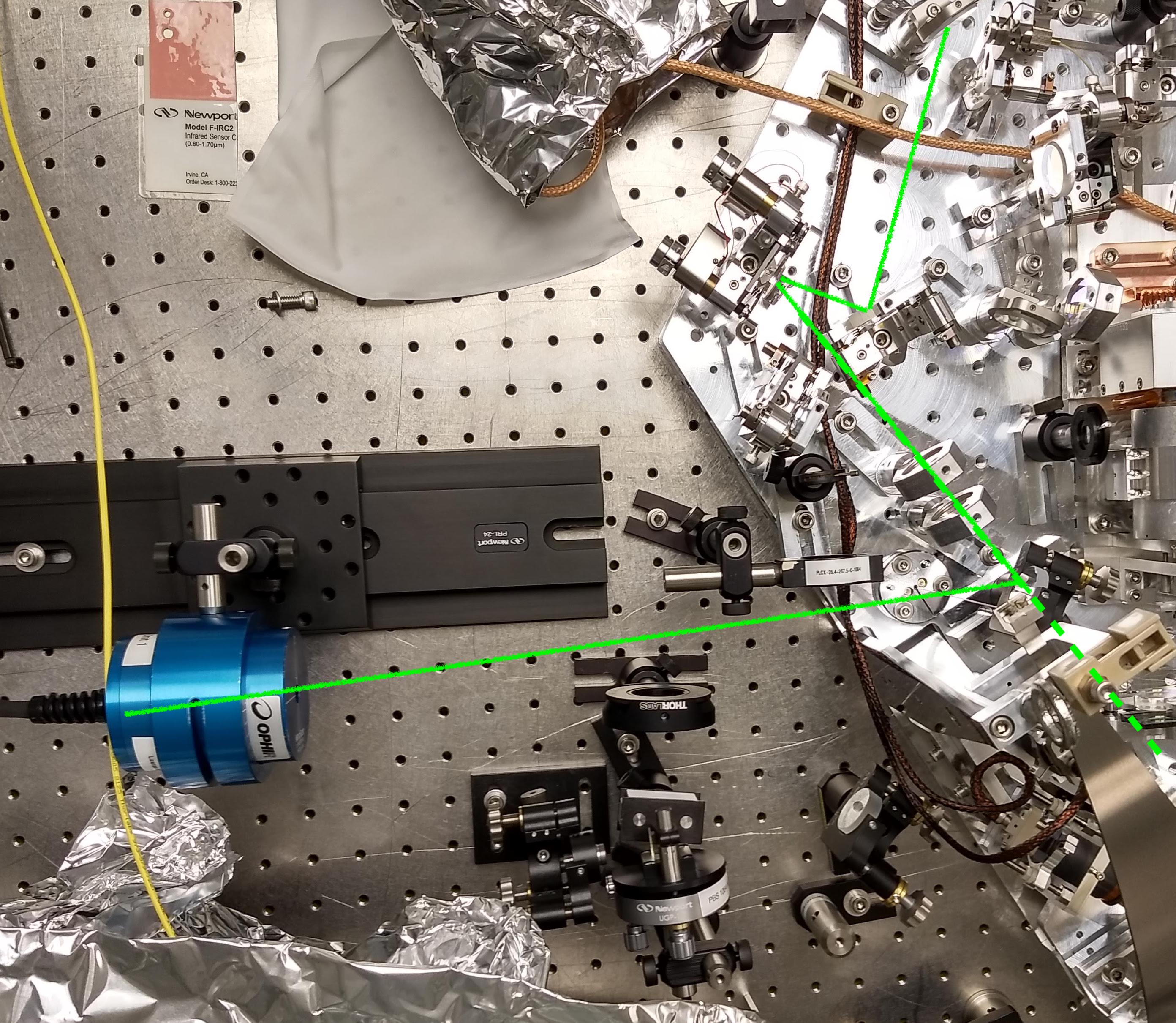
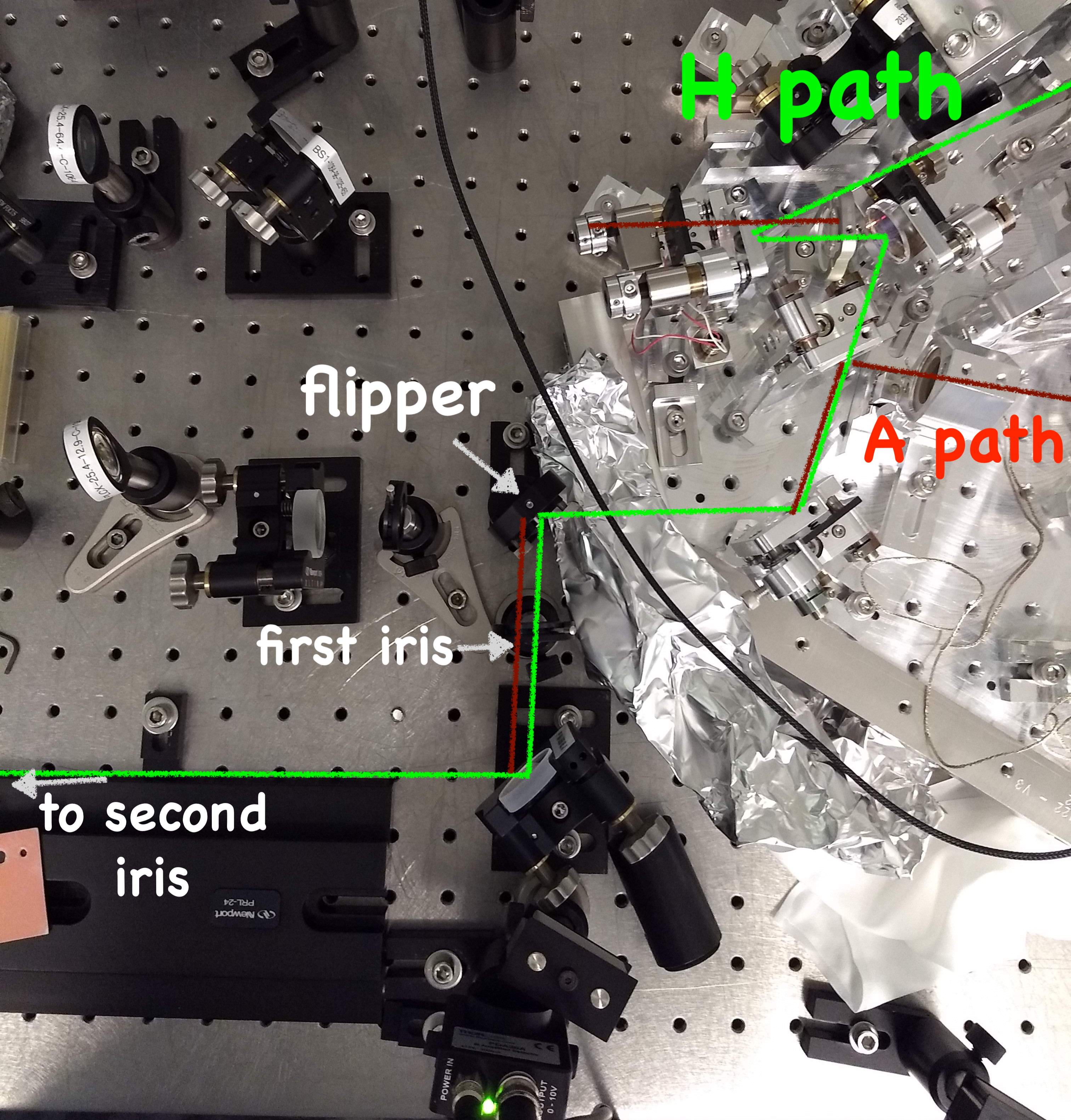
- I then took a look at the beam between H:M1 and H:M2. I put a steering mirror on the VOPOS just after H:L1 and H:L2, and sat the beam profiler on the table (see 6th attachment), the beam shape looks similar to earlier measurements (7th attachment), I don't think it is clipping on H:POL1 or H:M1.
- I then looked at the beam on the FC path (A path off the breadboard). I noticed that the green beam was slightly misaligned to the second iris. Not surprised since I adjusted the collimator way upstream
- While sliding the profiler on the rail I knocked one of the irises we use to co-align the H and A paths off the table.
- I switched to looking at the IR beam, with plans to realign the iris to it. I noticed that the IR beam is no longer clearing the first iris (see 8th attachment for layout of the off-VOPOs paths).
- I tracked this down to the flipper mirror, which is a 532 nm mirror. Camilla switched this from an IR reflector while hunting down the source of beam ugliness, but I think we should switch it back. The IR is clearly reflecting off the back surface of the mirror. I think we either want to switch back to a 1064 mirror, or ideally we would switch it for a dual reflector, so we avoid confusion while trying to co-align these two paths of different wavelengths.
- While looking for the source of the IR mislaignment I noticed that there are two green beams coming off A:M3 - a ghost beam is reflecting off the back surface. Maybe this isn't surprising? But it made hunting down the source of IR misalignment more confusing.
Still to do:
- Compare beam profile from nanoscan with CCD profiler?
- Switch the flipper mirror so it reflects at 1064
- Align the H path irises to 1064 beam again
-
Align the green beam to the irises, do a final beam profile of the A path and H path (unless we want to swap in the 100mm lens as suggested by Keita?)
IR beam reflection from the 1st surface of the flipper is still visible if you use Thorlabs card or Nikon IR sensitive camera.
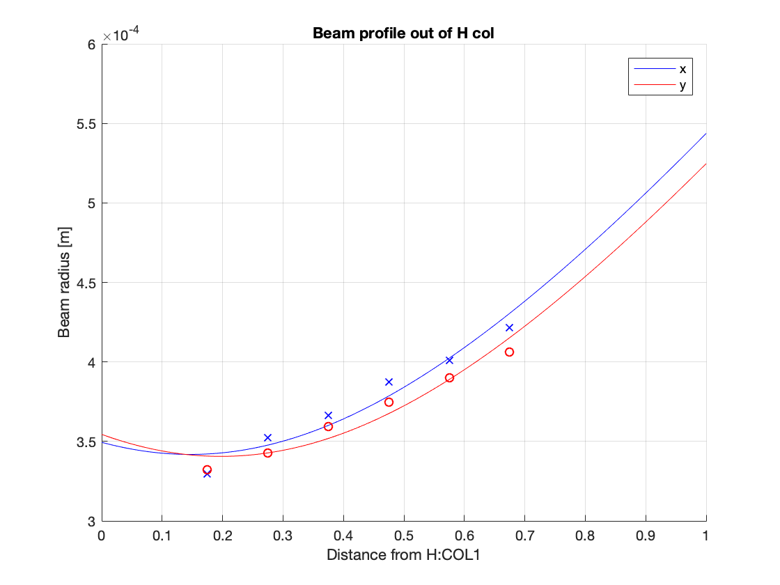
Yesterday I took some profiles of the H path and A path with the wincam.4 data poitns
- First I looked at the beam straight from the collimator, on transmisison of H:BS1.
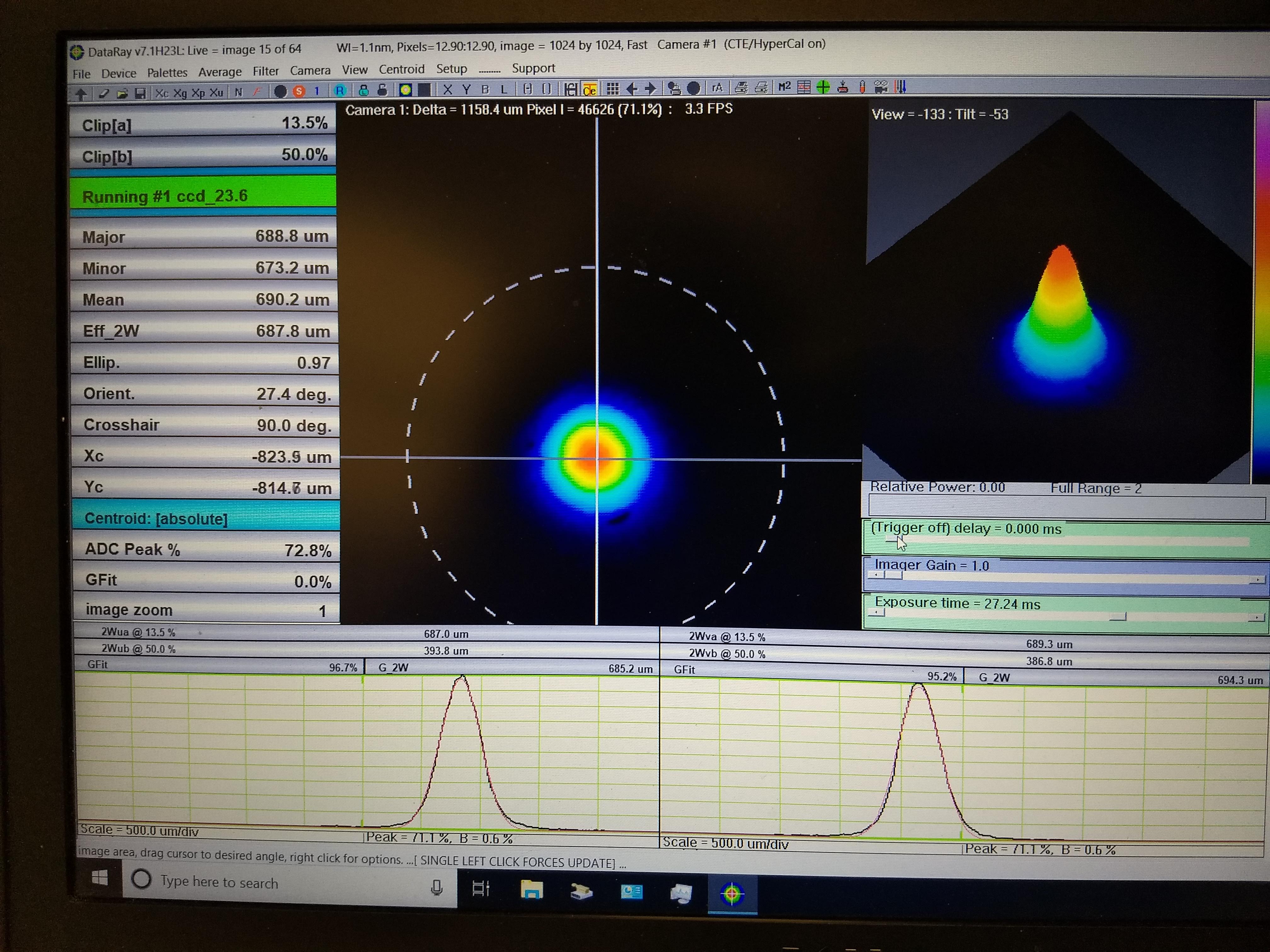
- Visually the beam looks less square to me on the wincam vs the scanning slit profiler (first attachment shows the beam close to the platform). The profiler has a big stack of ND filters on the front so I had to be careful in aligning the beam onto the camera, to avoid etalons and fringing. (second attachment shows the camera)
- I took a profile of the beam transmitted through H:BS1, same as Keita did earlier this week. I wanted to re-do this since I had messed around with the collimator on Thursday. I made a quick plot with the built-in fitBeamWidth ALM function. See third attachment for the plot, script also attached. I only recorded the 1/e2 beam width data. The beam waist position is maybe closer to the collimator compared how it was before, but it seems like it's collimated enough.
- I then worked on the green FC path (H path)
- I didn't change the flipper mirror, and just aligned to the weaker 1064 beam. With the OPO locked (vs scanning) and the more sensitive IR card I found this beam easily.
- The green beam needed a little bit of walking to be co-aligned to the red (not surprising after touching the collimator), it was a few mm off the center of the far iris and ~1mm off the near iris. I used H:M2 to align to the near iris and H:M3 to align to the far iris. This worked well.
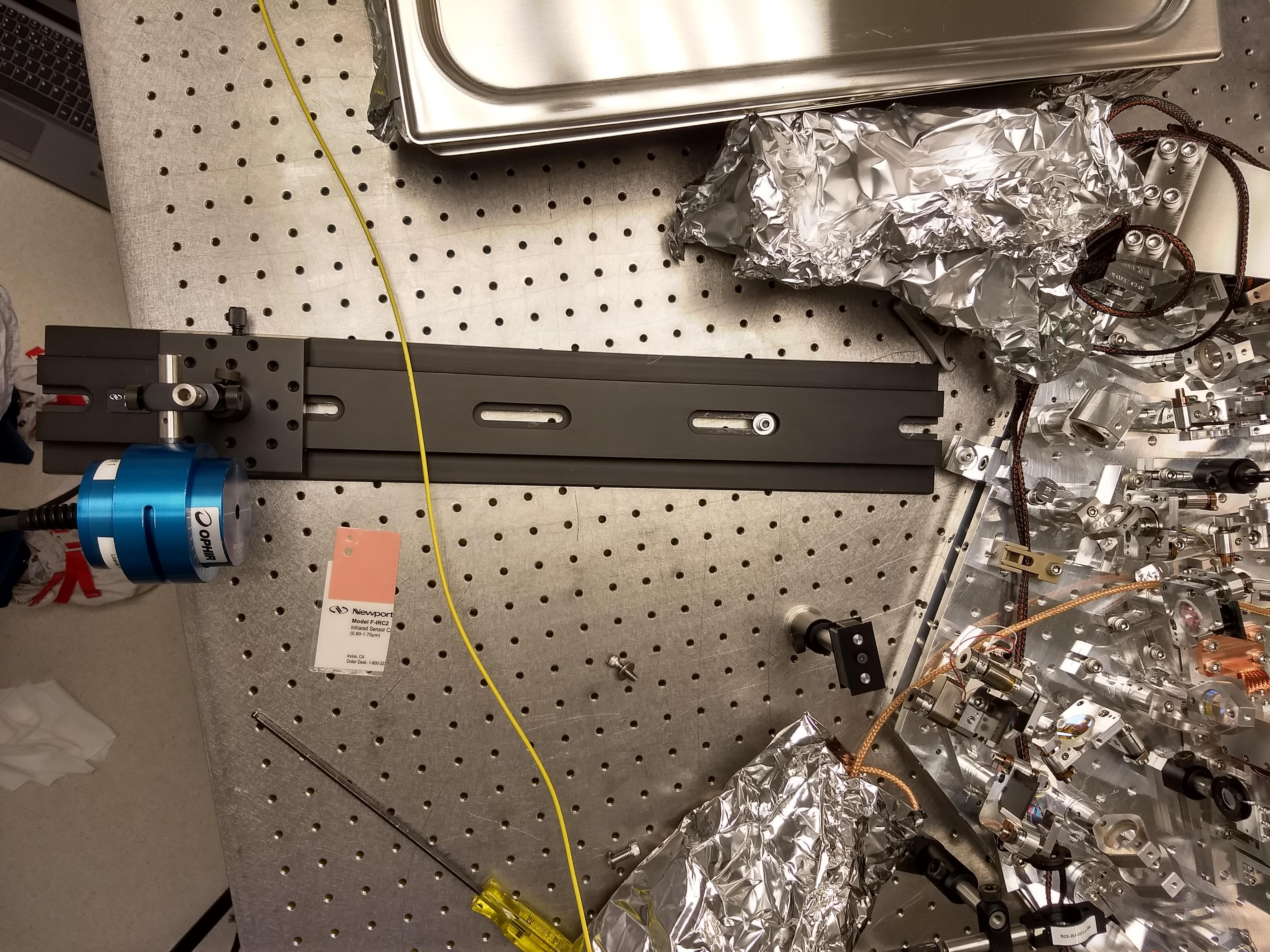
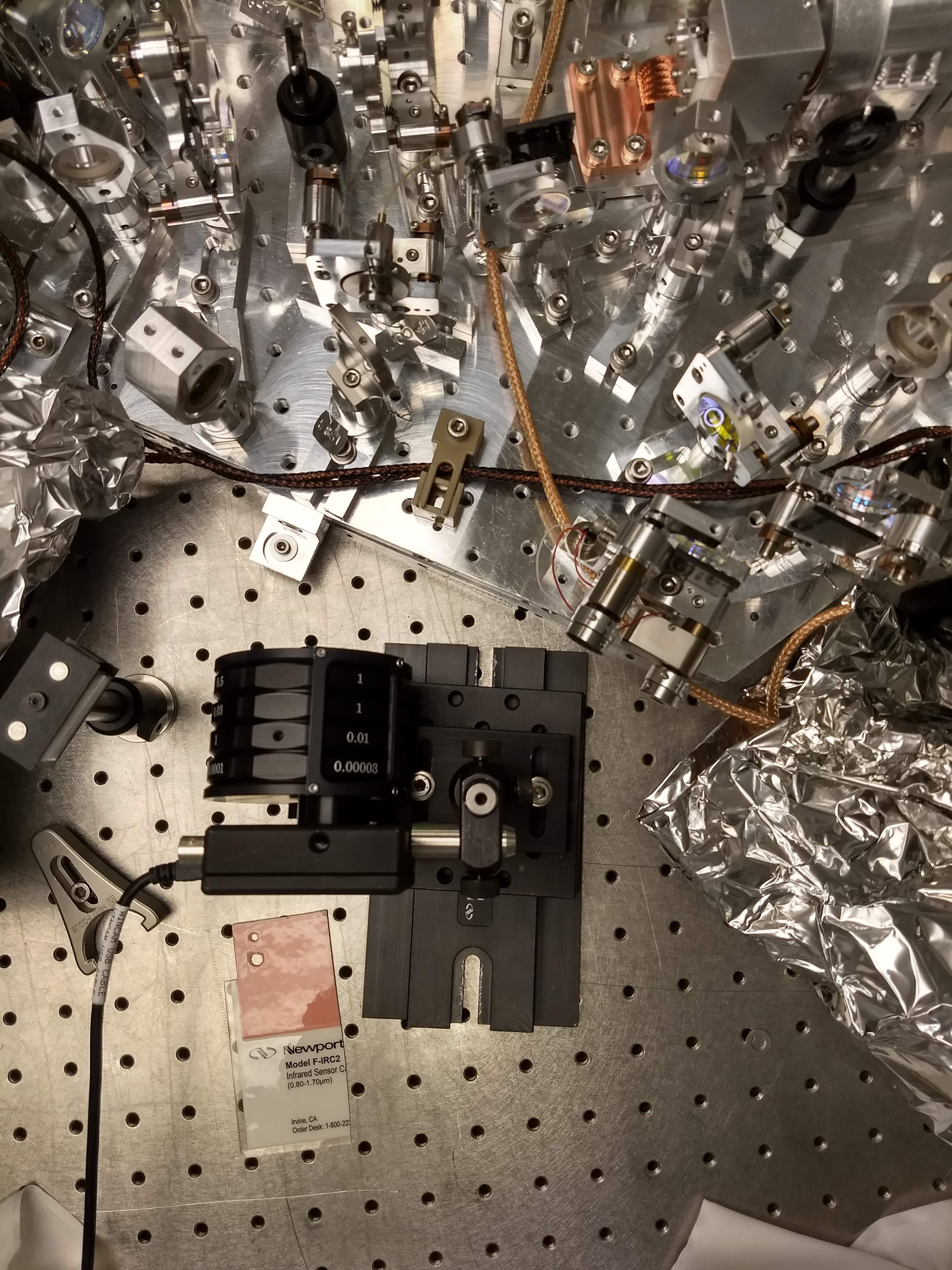
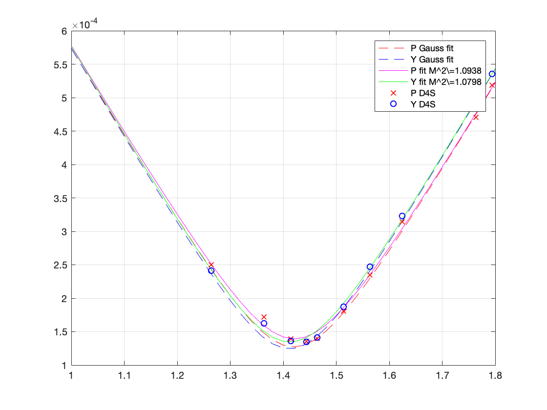
- I then took a beam scan of the H path off the VOPO platform, along the rail shown in this photo.
- Fourth attachment shows the measurement for the 532 nm beam, this looks pretty consistent with Keita's measurement earlier this week.
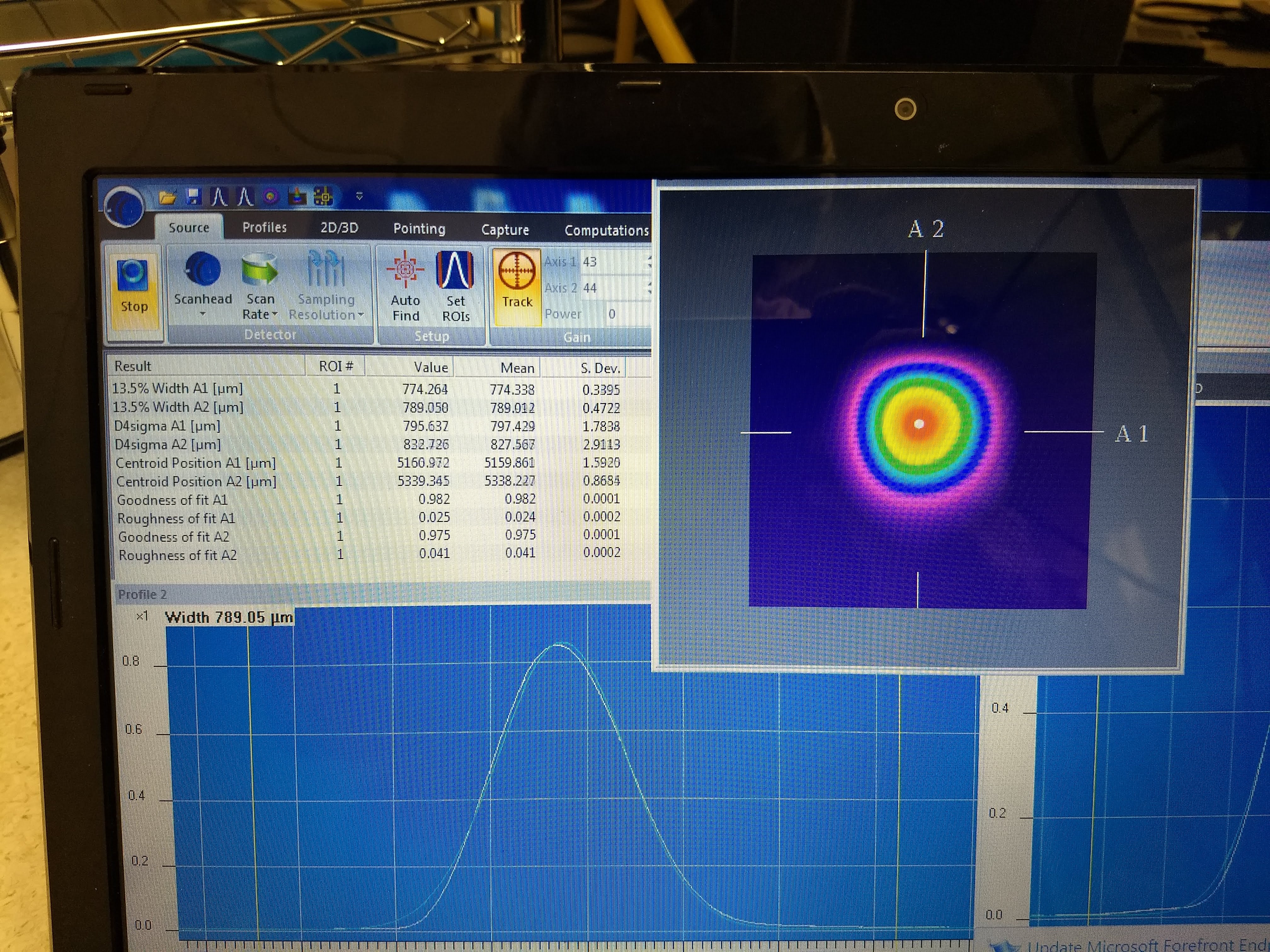
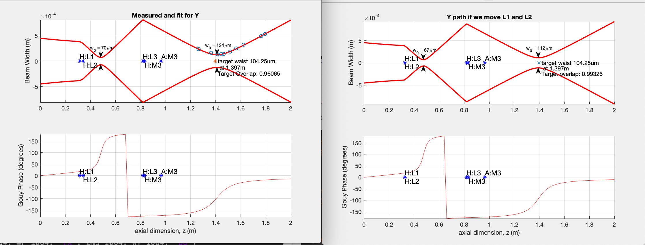
- The overlap with the expected beam looks pretty good (0.96), see 5th attachment.
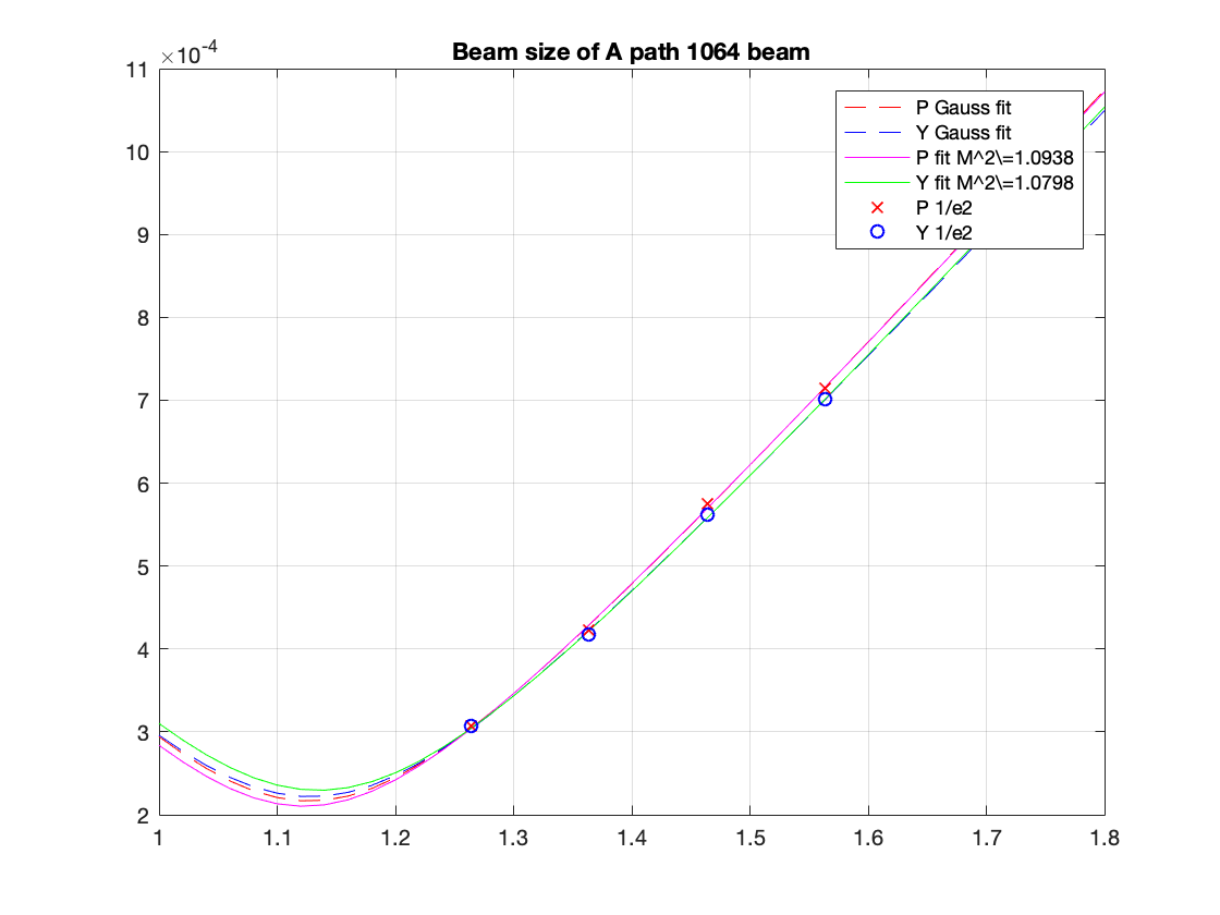
- While the profiler was set up I took a profile of the A path, thinking that the waists for the H and A would be co-located.
- It was tricky because the OPO did not want to stay locked, but I managed to get 4 data points (6th attachment), which suggested that the 1064nm waist (A path) is about 30cm closer to the VOPO platform the 532nm waist (H path). Is this expected?
- To make these plots I added the new data to Keita's script - see modematching7.m
G Path launcher update
I compared the mode shape coming out of fiber collimator with Sheila's measurements detailed in alog 57906. To make apples-to-apples comparison, I used 1/e^2 radius, not D4S/2. The numbers are mode overlap with ideal mode (which is supposed to be 330um waist at the launcher).
Anyway, they seem to be fairly different from each other, and given that, I also expect some alignment change. Further, though the beam now is better matched to the ideal mode than it used to, Sheila should have adjusted the lens positions accordingly.
So, all in all, it seems like we need to at least align the beam to the OPO and scan the cavity to measure the 2nd order mode peak relative to 00.
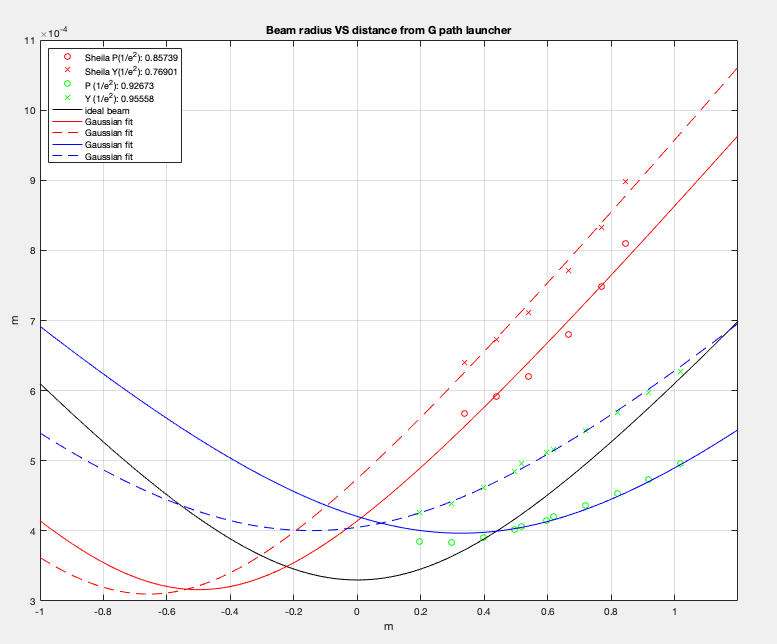
I see your new measurements and Sheila's. I missed that she set up the G:path to the Diamond fiber and uLS collimator. She must have moved the collimator to make as similar a waist as possible, which made a virtual waist behind the collimator. You seem to have collimated the beam now, which is getting w=400um-450um.
I did this at LLO and got a less astigmatic beam with w~=450um. I could imagine it is a little bit smaller than that. The mode matching solution used is up LLO55830. It uses a lens before and after G:M1, rather than two lenses after it.