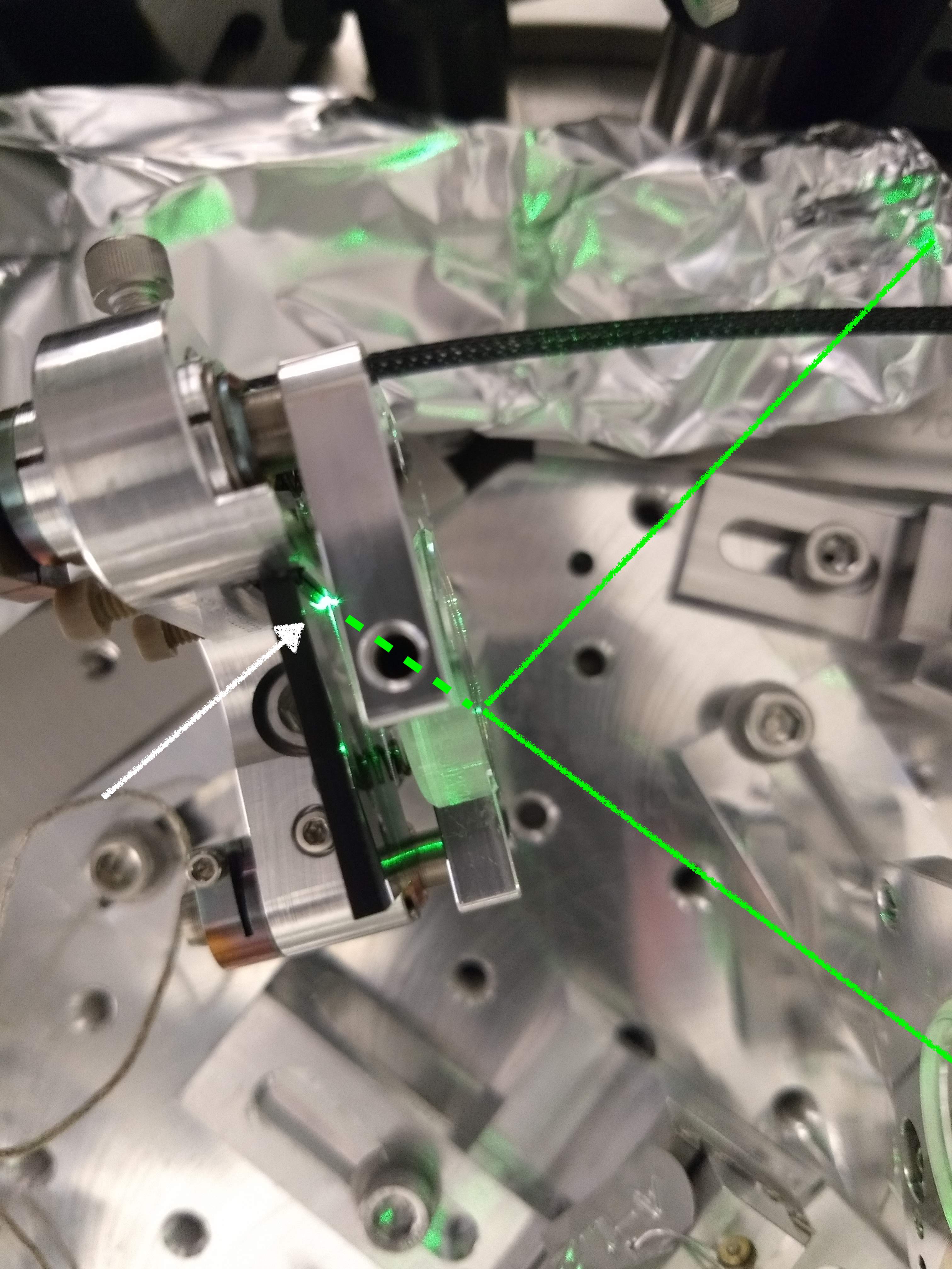
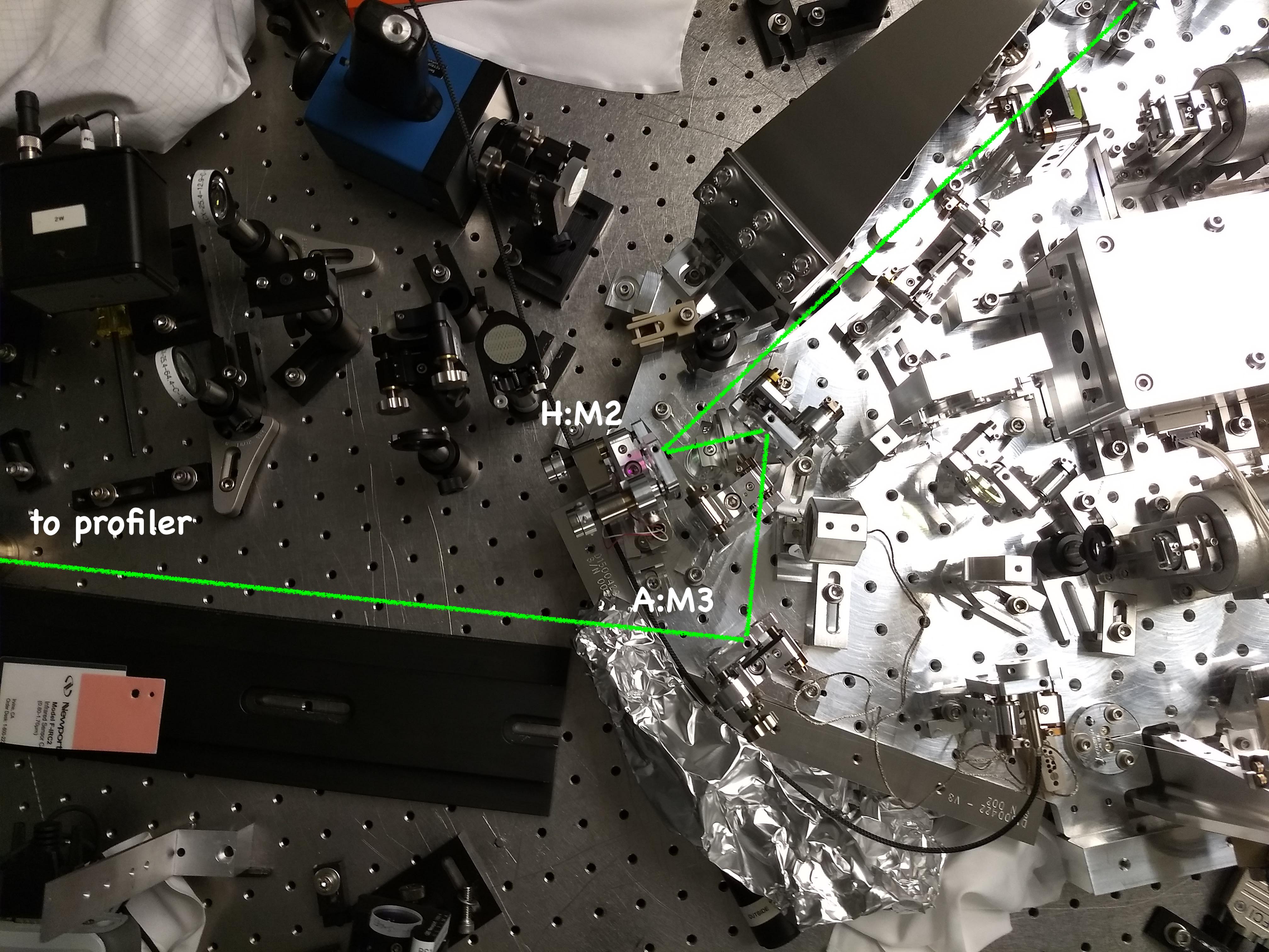
Today we looked at the H path again, we found the green beam shape is still bad after being combined with the A path. We also noticed that there is a large green beam being transmitted through A:M3, and scattering off the black glass holder. A:M3 should be a dual reflector for 1064nm and 532 nm, but in reality it is only reflecting about 50% of the 532nm light. We'll need to repace this mirror.
Beam shape between H:L2 and H:M2, after blade spring
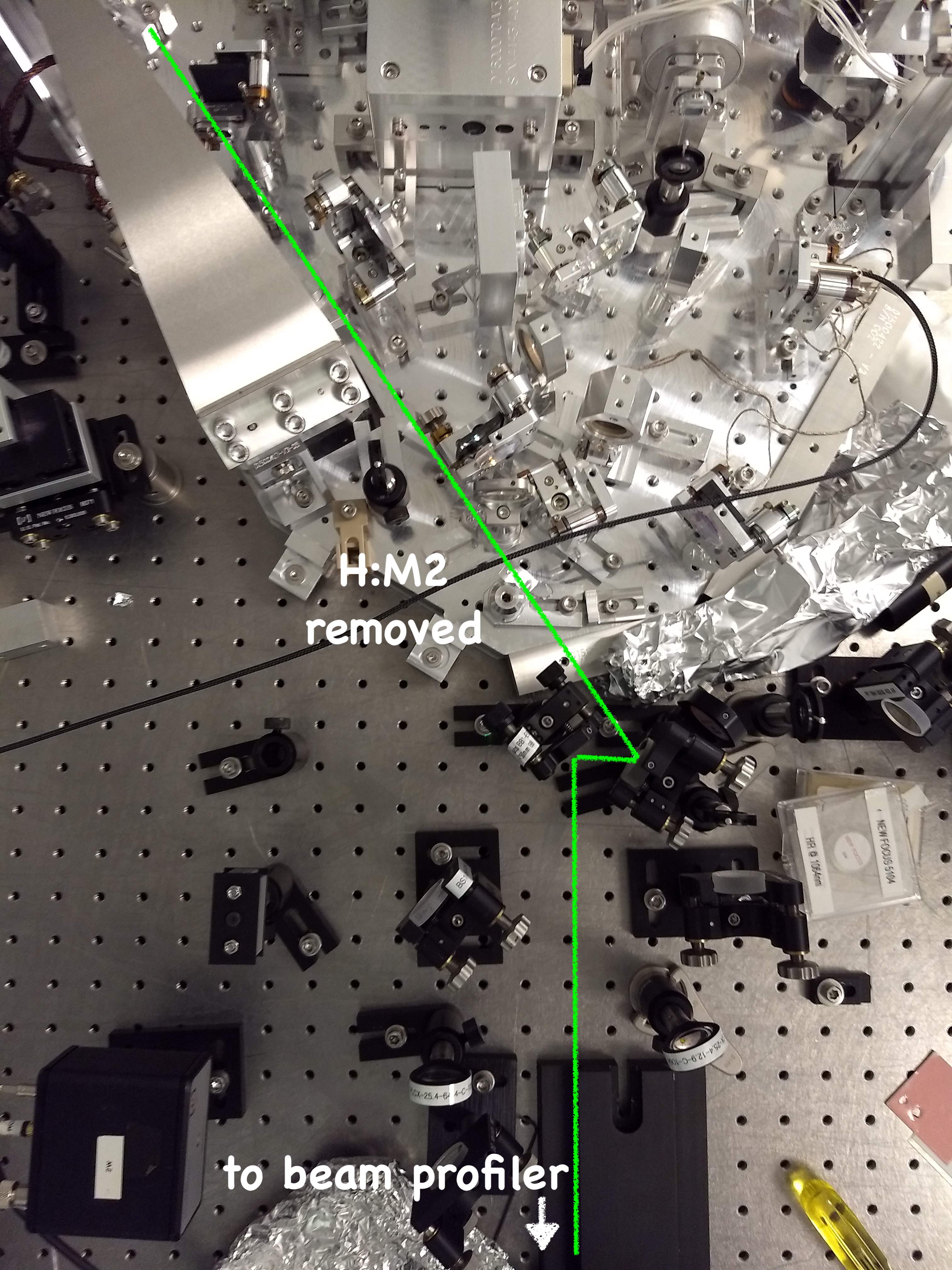
- Keita wanted to check the beam shape close to H:M2 and make sure there was no clipping from the close-pass with the blade spring and B:M3 mount.
- We removed H:M2 and steered the beam to the profiler (first attachment shows the beam path).
- The beam here had some extra power in the wings (not a perfect Gaussian) but was ok, see second attachment. We tried steering H:M1 while looking at the beam on the profiler, but could not change the beam shape, so we are definitely not clipping.
Another profile after A:M3
- We then locked the OPO (had to adjust the laser current to avoid mode hopping, and change the polarization going into the F path fiber to get the error signal to cross zero).
- We aligned the irises to the 1064nm beam, and then co-aligned the H path green beam.
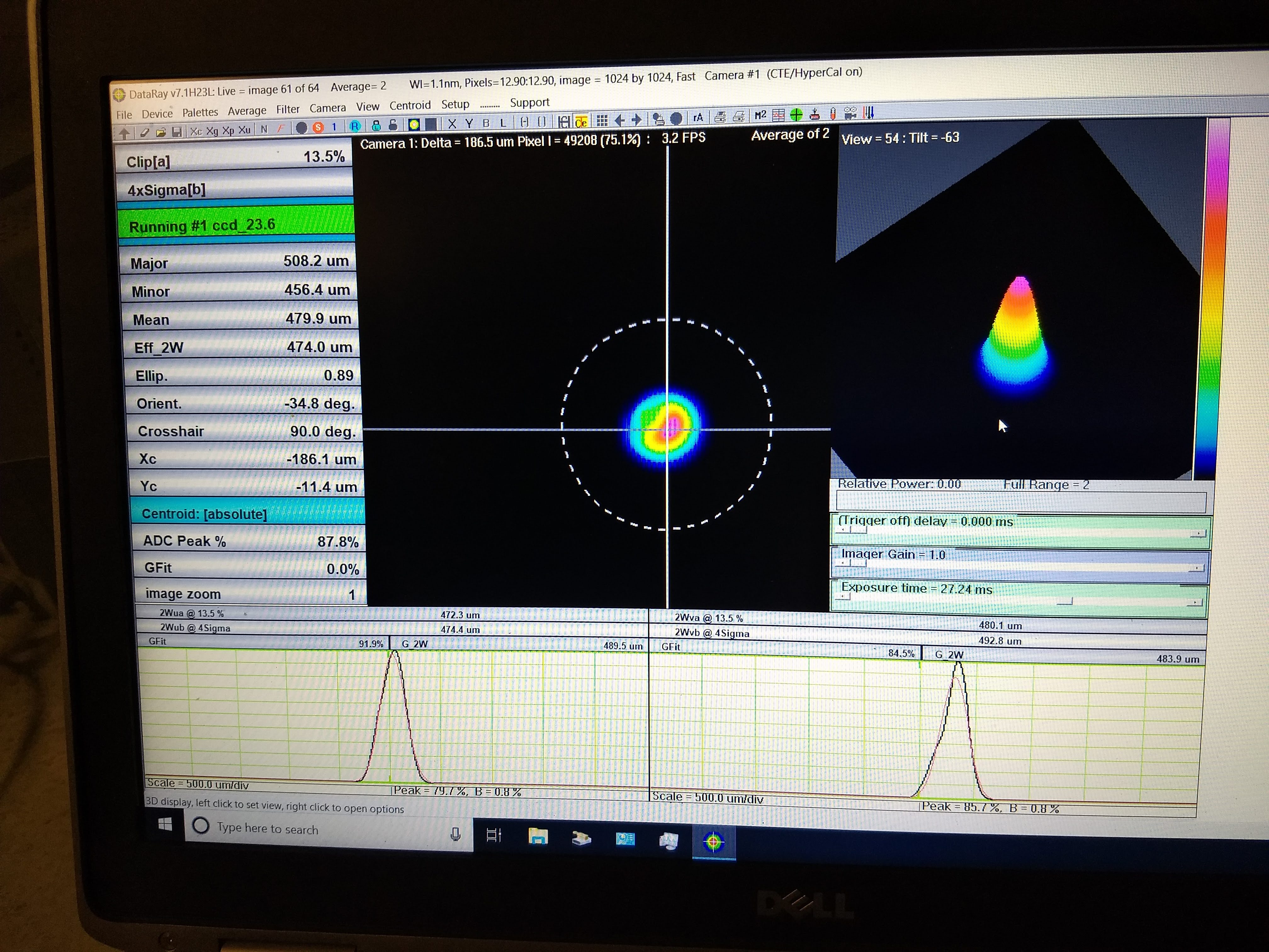
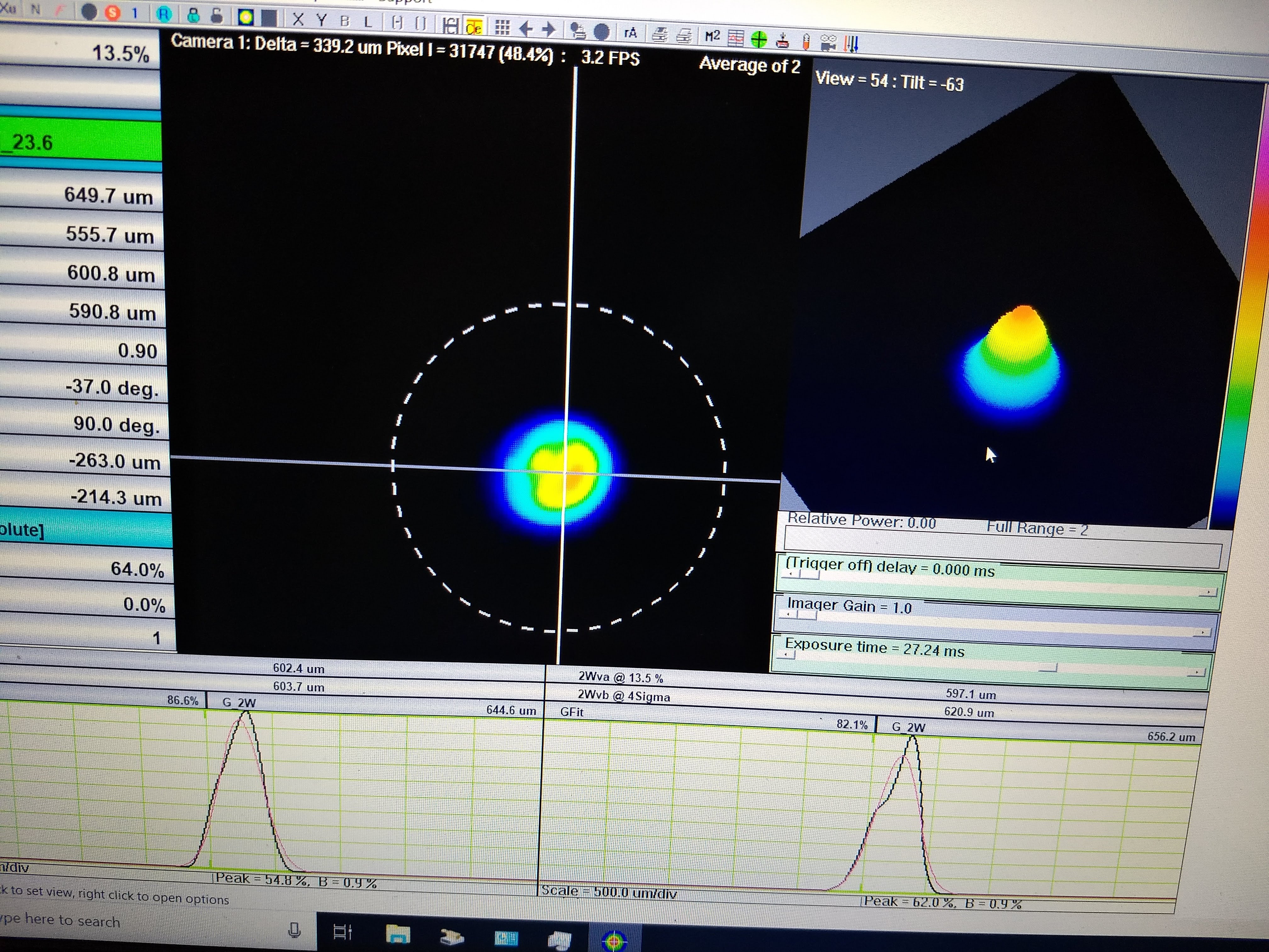
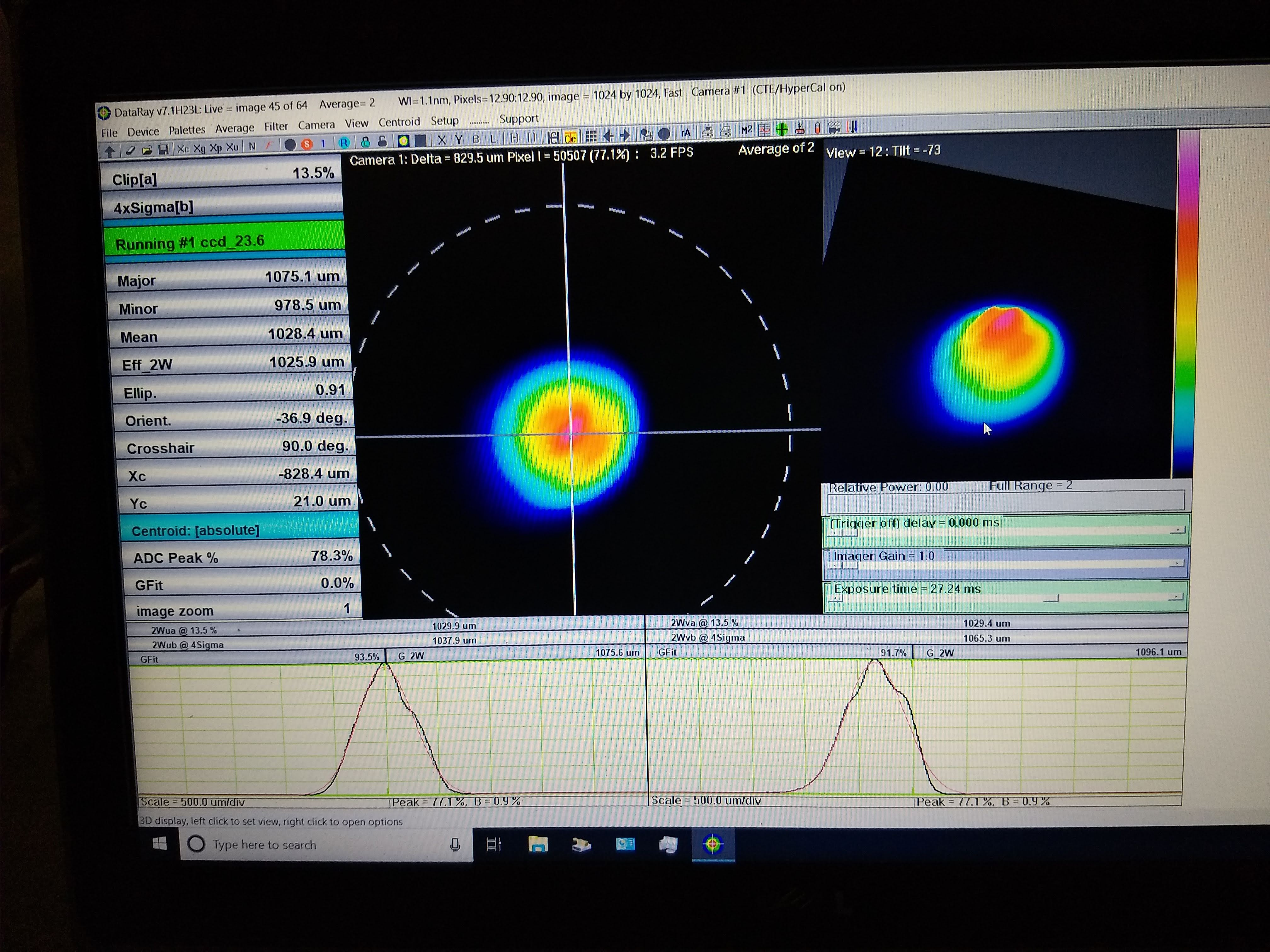
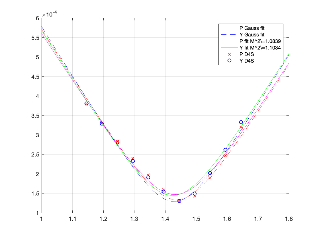
- We took a profile of the green H path beam (third attachment, which shows the 4 sigma beam width). Even though the mode overlap is good (~0.95) the beam shape was worrying (see fourth, fifth, and sixth attachments for the shape at different positions along the beamscan rail).
- We tried tweaking H:M1 again to see if we could change the ugly beam shape. No dice.
A:M3 seems to be the wrong optic
- We spotted a bright green beam on transmission of A:M3. This transmitted beam is half hitting the black glass and half hititng the black glass holder, though it is hard to see (7th attachment)
- We decided to measure the power at different locations along the H path and found that A:M3 is only reflecting ~50% of the green light! This should be a high reflector for 532 and 1064
- Keita will check what the splitting ratio of H:BS1 should be, but it seems like it only reflects 25%.
H path power budget
| Location | Power (uW) |
| H:BS1 transmission | 412 |
| H:BS1 reflection | 141 |
| H:POL1 transmission (wrong polarization) | 1.5 |
| Between H:M1 and H:L1 | 130 |
| Between H:L2 and H:M2 | 127 |
| Between A:DC2 and A:M3 | 120 |
| After A:M3 | 60 |


About H:BS1 50:50 splitter:
This is an aLIGO 50:50 BS for S-POL (E1000869). Though the numbers in Georgia's alog indicate that T/R~0.75/0.25, that might be due to wrong polarization because the in-air HWP upstream of the fiber was adjusted to mimimize the P-pol going through the polarizer downstream (H:POL1) without knowing that H:BS1 might be strongly polarization dependent. We'll measure the real splitting ratio for S-pol.
Jun 15: A:M3 was the correct optic, AOI problem, and probably green polarization problem too (Camilla, Keita)
1. A:M3 reflectivity for IR was not 1. Most likely that's because of wrong AOI.
Locked OPO using IR and measured the power of A:M3 reflection as well as incoming beam. Power fluctuated a lot, but:
Incoming 0.56~0.61mW, refl 0.54~0.59mW. Accuracy is suspect but reflection looks smaller than 1.
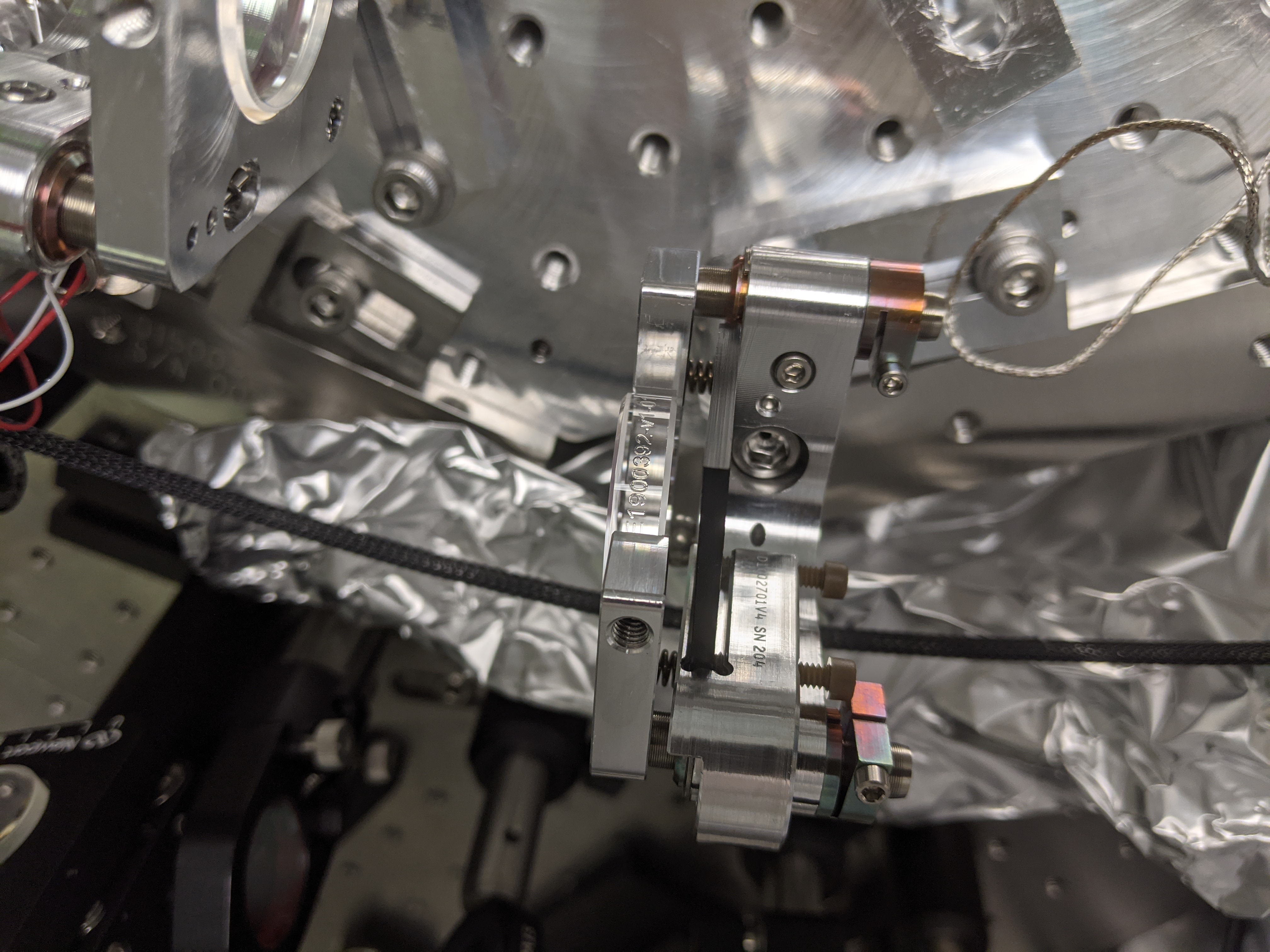
Checked the engraving on the mirror barrel of A:M3 (1st picture) and it was E1900392-v1 (dual wavelength HR, AOI=35-45 deg, S pol), i.e. the correct optic.
If you look at the 2nd picture you'll see that the AOI on of this optic is roughly 110/2=55 deg. Coating vendor's witness piece measurement (see page 4 of E1900392-v1coatingVendor.pdf) shows that AOI~55 deg is not really ideal.
2. Green reflectivity VS AOI
Took the optic out of the mirror holder on the OPO platform and monted it on a class A mount/post on a dirty baseplate to quickly measure reflectivity VS AOI using the green beam reflected by 532nm polarizing cube on the optics table.
R~98% at AOI~45deg. (0.85mW reflection. 0.87mW upstream. Measured the latter within ~1min of the former.) Not too crazy even though it's supposed to be larger than 99%.
~87% at AOI~55deg. (0.73mW reflection. 0.84mW upstream. Measured the latter within ~1min of the former.)
We obtained different data set earliner (~93% for AOI~45 deg and ~90% for AOI~35deg) but these are more suspect as the measurement interval between the reflection and upstream was larger.
3. Green polarization, H:BS1 identification.
H:BS1 was the correct optic too (3rd picture, showing E1000869-v1 engraving, so this is 50% S-pol splitter as per design).
I didn't have a convenient way to measure the polarization coming out of the launcher. Expecting that the P transmission is bigger, I thought that minimizing the H:BS1 transmission will ensure that the polarization is mostly S. I rotated the HWP in the in-air path to minimize the transmission and ended up having trans/refl ~ 210uW/252uW. Not sure why this wasn't 50:50, maybe the AOI is off by a large amount just like A:M3 but I didn't measure it.
On H:POL1, P/S=refl/trans~ (246nW-130nW)/255uW=116nW/255uW, this was pretty good.
After this adjustment, green reflection VS incoming power on A:M3 was refl/in~277uW/305uW~91%. This is roughly consistent with ~87% at AOI~55deg obtained in 2: above.
4. Tomorrow
We'll change the AOI on A:M3 from 55 to 45 deg.
Right now the green beam going into FC path is not parallel to the IR path between the Faraday and dichroic though it looks as if they should be on the drawing, and I expect the change of AOI will mitigate that too.
I don't expect that the ugliness of the beam will be mitigated, though.
Today continued work on the H path. We fixed the angle of A:M3 to have 45 degrees AOI. We took a beam profile along the H path again, it looks the same as on Monday (makes sense). We then checked that the polarization is vertical on the H path.
Adjusting A:M3 angle
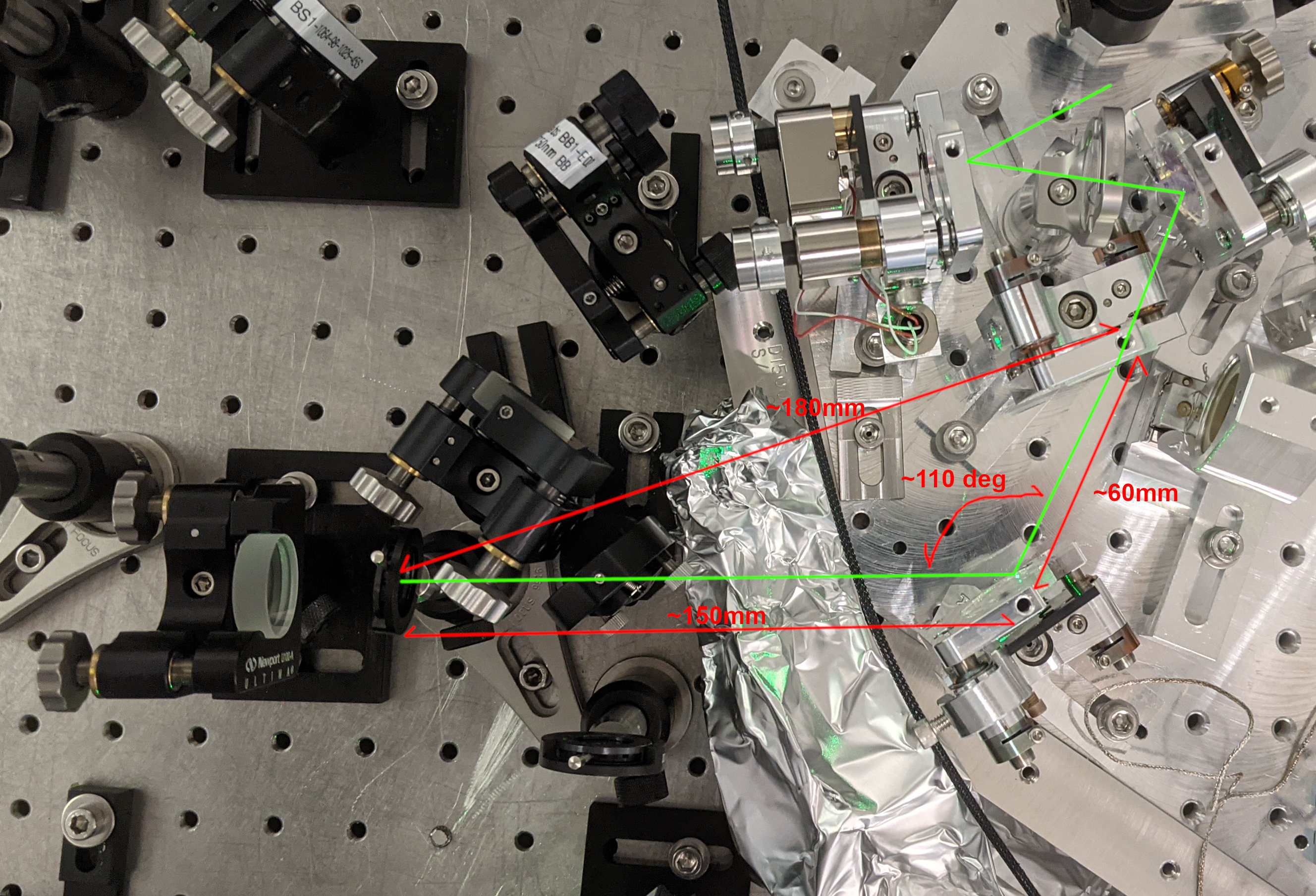
- First Keita measured the distances from A:DC2 to A:M3 and A:M3 to the retroreflector, so we can put the retroreflector back later
-
d_DC2_to_M3 = 62mmd_M3_to_RR = 181mm
-
- He adjusted the angle of A:M3 so it was parallel to A:DC2. We used trigonometry and measured the new beam angle to be 89.4 degrees.
- We tried to measure the power before and after A:M3, but the power measured on the power meter was fluctuating, and consistently measured more power *after* the mirror than before. We checked things like background light levels, power measurement dependence on beam size. In any case the reflectivity seems more reasonable now, close to 1.
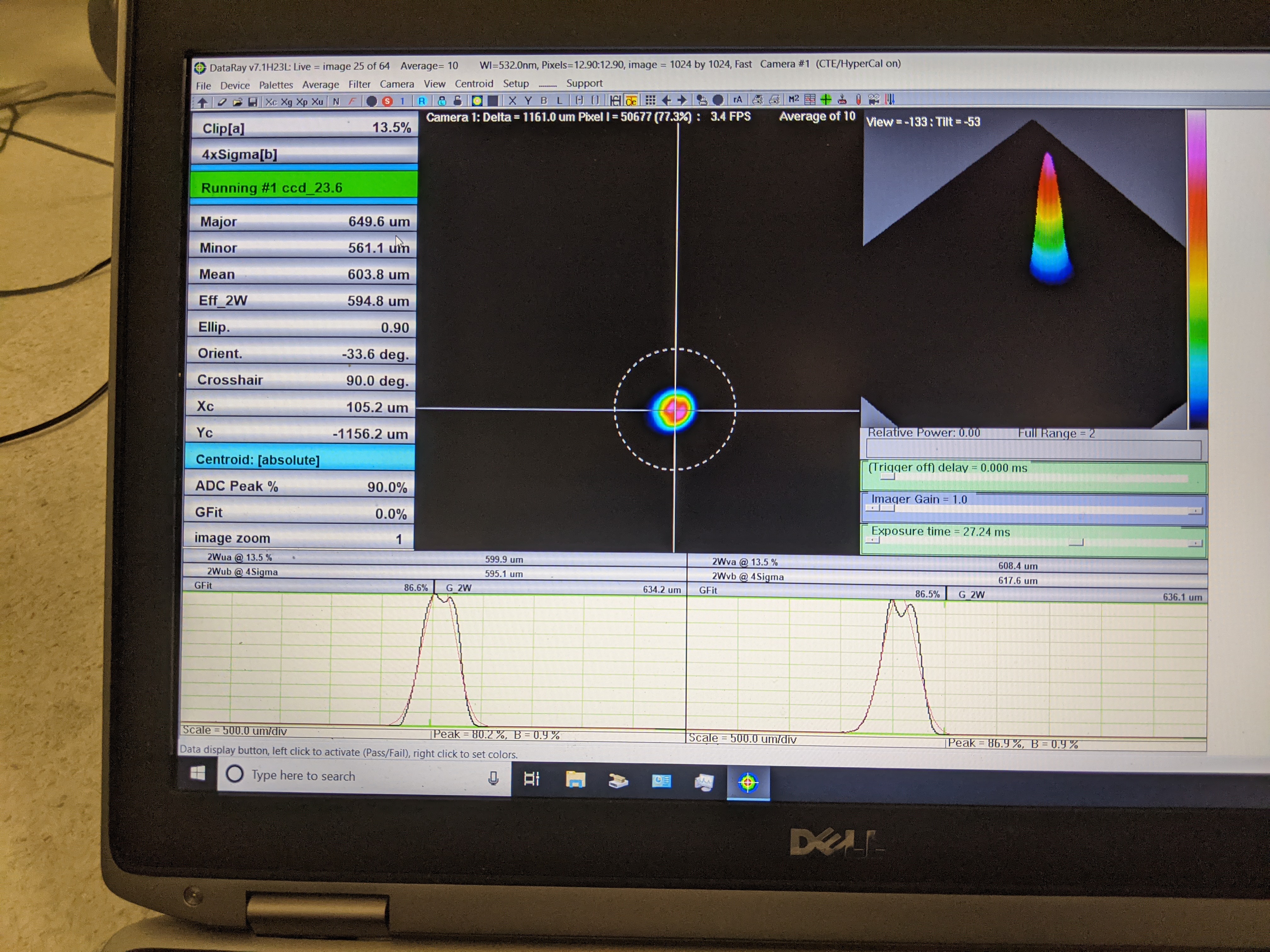
Beam profile
- We set up the beam profiler directly after A:M3 (see first attachment), we had to move the REFL PD path to make space for the rail
- Keita noted that the beam was pitched up, and higher than 4" from the table, so adjusted the pit of A:M3
- When we first set up the profiler the attenuation was too low for the main beam, but we saw two ghost beams on either side of the main beam, when keita rotated the scan head the ghost beam moved a lot while the main beam barely moved so we concluded these beams were from the attenuators.
- Note: the wincam sensor is 8.2mm behind the front of the case
- The beam profile looks very consistenet with monday's measurement (second and third attachments), with the same ugly mode shape seen on the far side of the waist (fourth attachment)
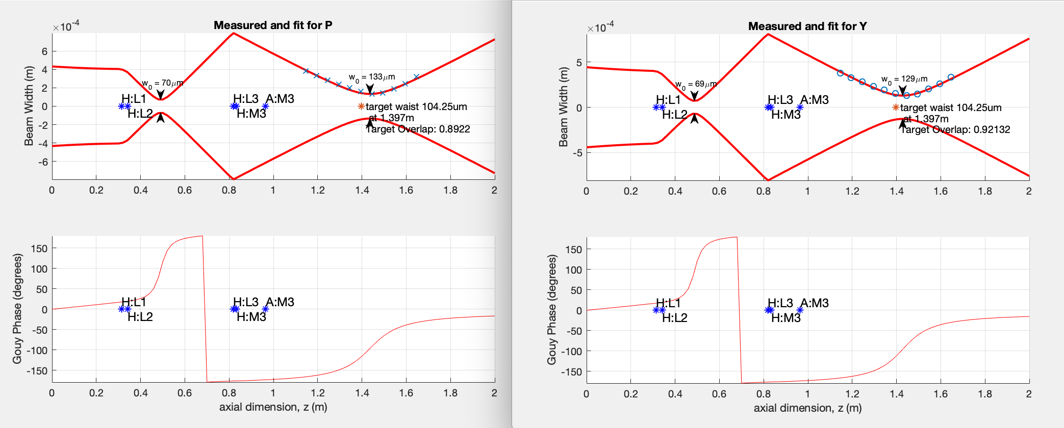
- The overlap is not great 89% in P and 92% in Y. We're thinking about switching H:L2 to the 100mm lens. If we move H:L1 upstream 1.8cm and H:L2 (100mm ROC) downstream 6.05cm we should have an overlap of 1.
Polarization
- Keita checked the polarization on the H path with a Brewster angle polarizer. We measured 270uW input, 180uW reflection to the left, 50uW reflection to the right, and 1uW transmission, suggesting an s-polarized beam.
Ghost beams
- We spent some time looking for ghost beams, wondering if such a beam could cause the weird mode shape we see.
- We noted that there are two ghost beams on the mount of H:L3. One is from the AR surface of the H:BS1 beamsplitter which is right after the collimator. The other is from the AR surface of H:L3, reflecting off H:M2 and then hitting the mount.
- We also see a green beam on the mount of A:DC2, this is on reflection of A:DC2.
Jun 16 addition:
Yesterday, before mode matching measurement, I readjusted the green HWP on the laser side such that the transmission/reflection ratio of H:POL1 is minimized (P-pol/S-pol~2e-4). After that I remeasured the transmission and reflection of H:BS1: T~201uW, R~249uW, or T:R~45:55. Doesn't sound totally crazy now.
After this I also used calcite Brewstar's angle polarizer on the H:BS1 transmission coming out of the VOPO platform and confirmed that it was S-Pol, so the light coming out of fiber should be S.
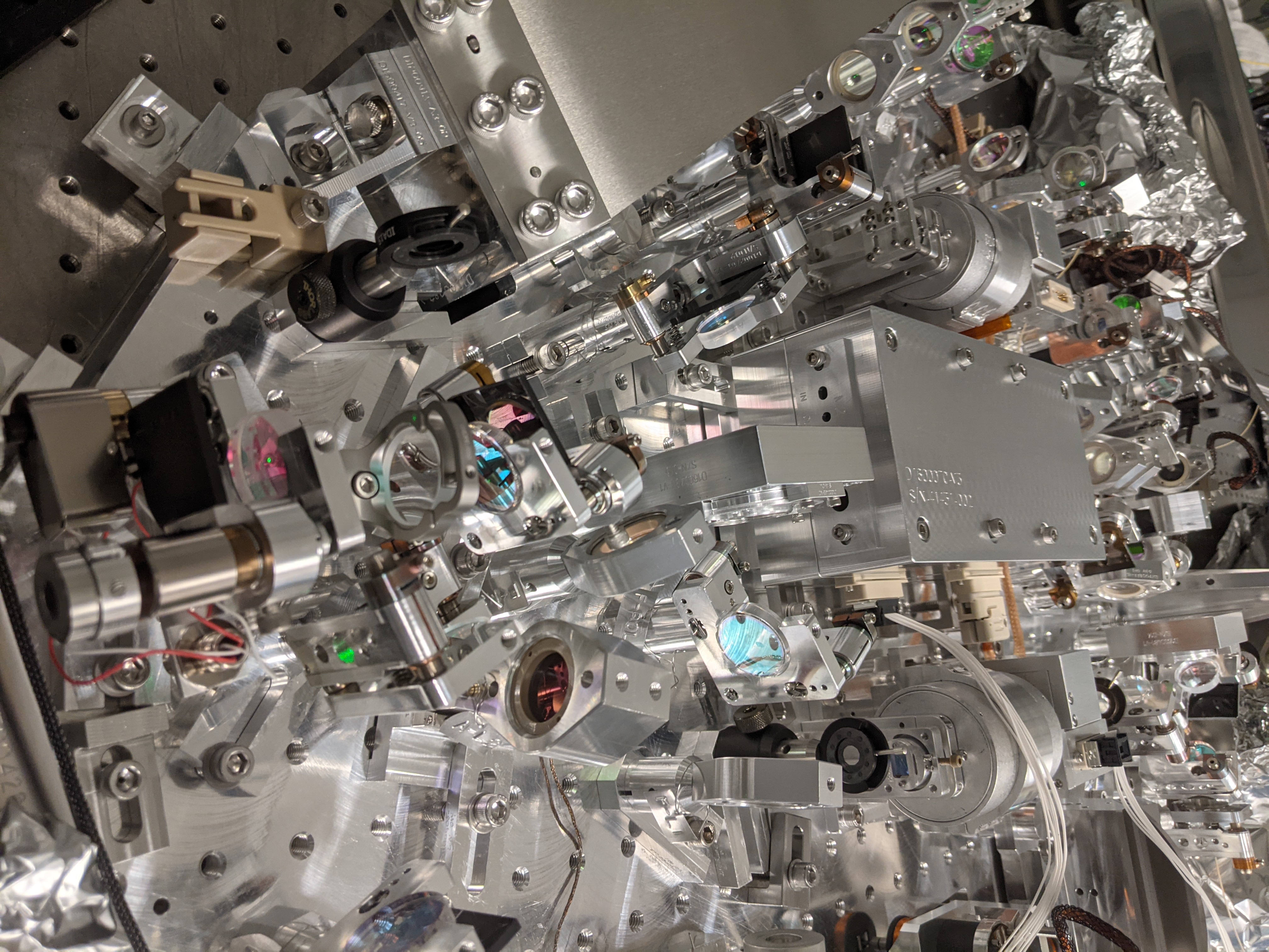
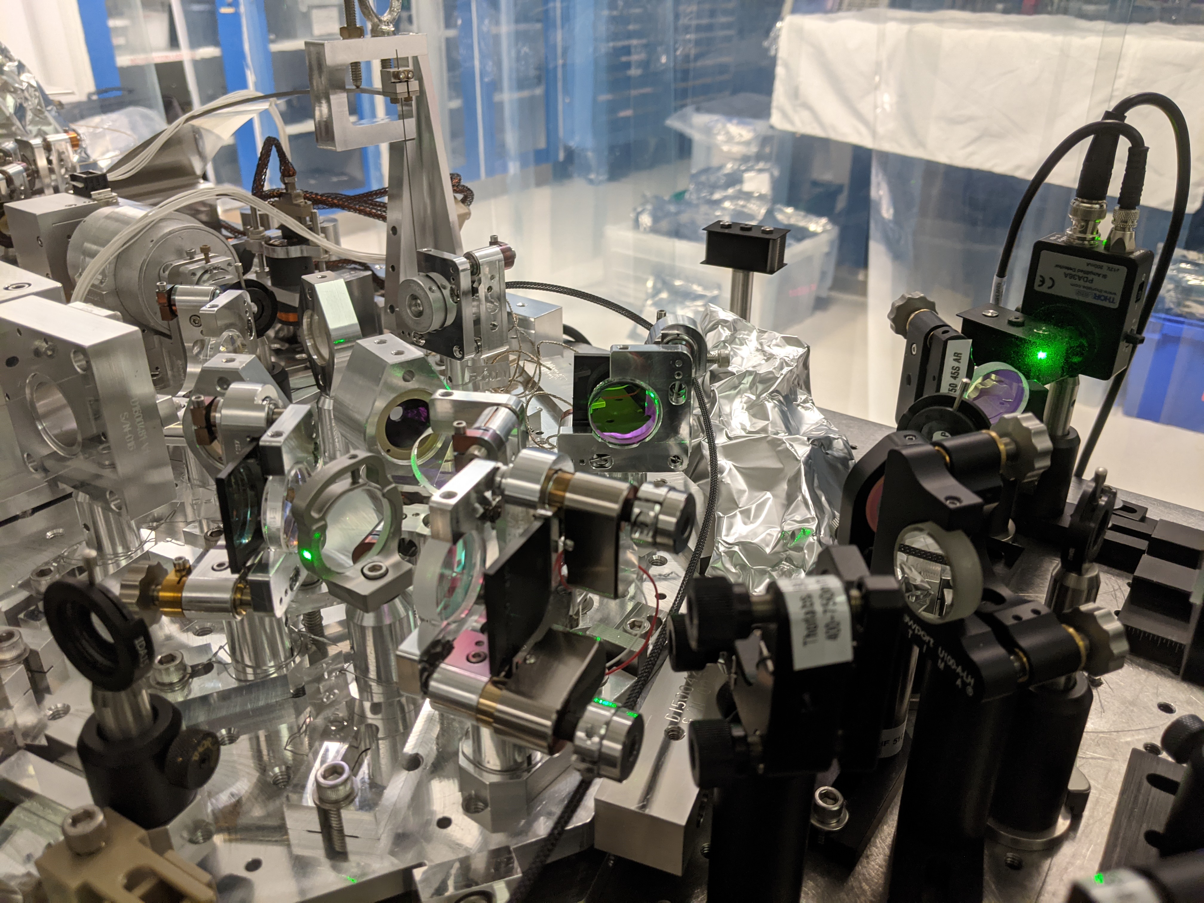
Also noteworthy is that the VOPO platform looked "cleaner" (1st photo) after we set the polarization right and changed the AOI of A:M3. It used to be green spilling all over the place (2nd photo).
Jun 17: H green path matching mostly done (Camilla, Keita).
Today we swapped H:L2 to 100mm ROC from 150mm following Georgia's calculation, but after doing that, somehow it turns out that it's actually H:L1 that needs to be swapped (as was predicted in alog 59158). So we swapped L1 and L2 (H:L1 ROC= 100mm and H:L2 ROC=150mm), and found that though it looked as if we could place H:L2 at a good location we couldn't in reality because it would interfere with the base of the sus wire clamp(??). Matching was bad on either side of the base.
We got back to 150mm ROC for both, and moved them closer to the collimator to get a better waist location than yesterday. We overshot a bit but now we're getting ~98% (P) and ~96% (Y) overlap instead of 89 and 92%, though M^2 is still bad as expected. We don't intend to refine it further.
(BTW we also changed the direction of the lenses such that the curved surface faces the collimated beam. Funny thing is, somehow I rememeberd for a very long time that the other way round was the good direction to minimize the spherical abberation when focusing a well collimated beam, but I was wrong.)
We still have to refine coalignment of IR and green. We'll also measure IR loss on A:M3.
Jun 18, H path done.
1. IR and green coalignment in FC path.
Closed the green shutter on the laser, opened the IR shutter, locked VOPO using IR PDH and centered two irises in FC path that were previously centered on the green beam. The change was not big but not negligible (unsurprising). Shuttered the IR off and opened the green shutter.
Used H:M2 and H:M3 to center the green beam on both of the irises.
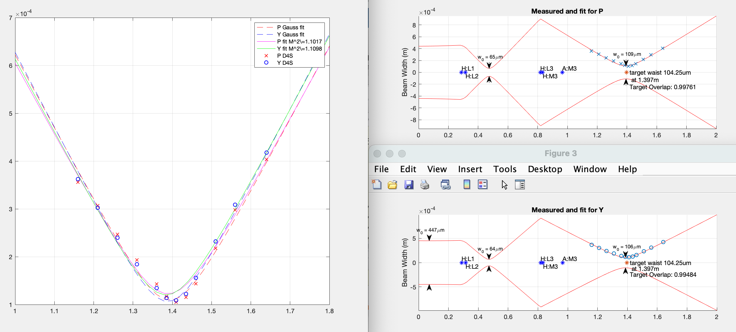
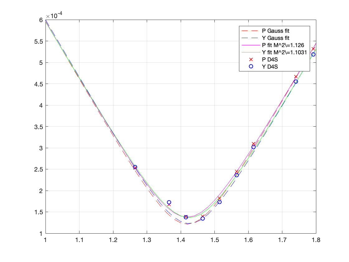
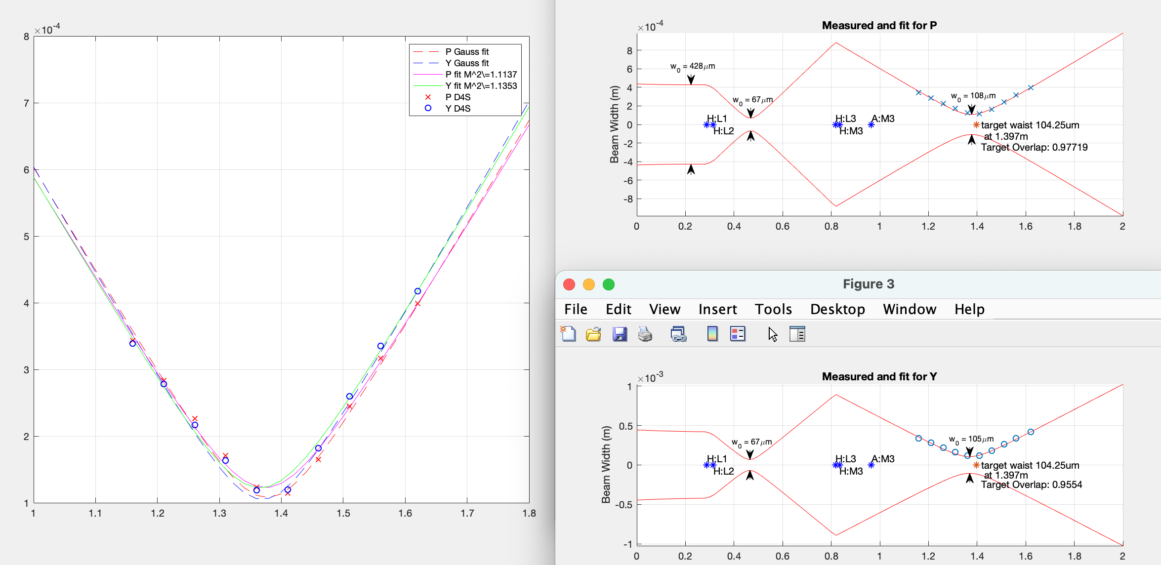
2. H path green mode matching final measurement, great (on paper, don't get overexcited).
Since the beam spot should have moved on H:L3 lens in the step 1. above (H:L3 is between H:M2 and H:M3) I made the final scan using WinCam.
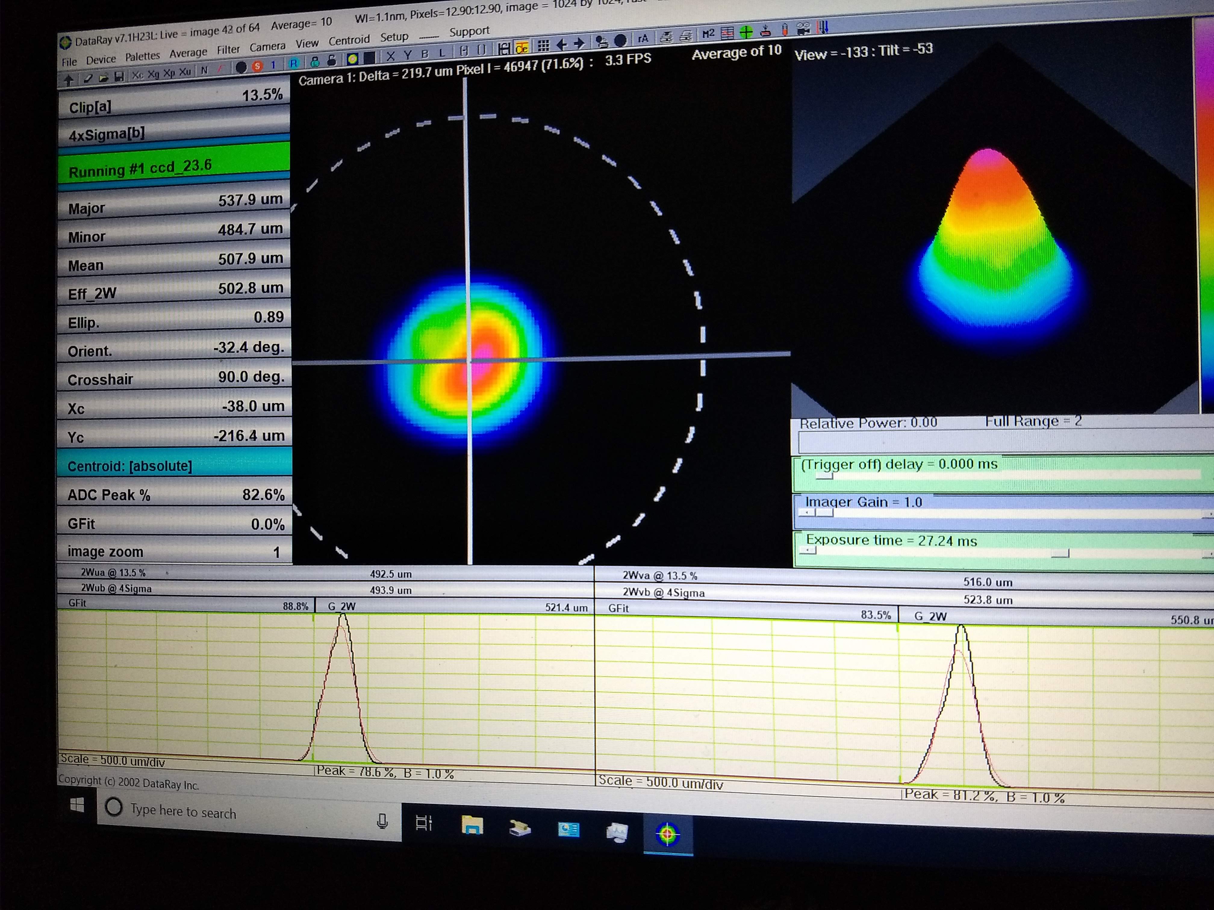
Surprisingly the waist position happened to get closer to the ideal position and the matching looks perfect on paper (1st attachment, 99% overlap both P and Y). Don't get overexcited, this is because we're pretending that the beam is Gaussian, which it is not (2nd attachment, this is the far field data).
As I wrote in the prefious alog entry we won't attempt to fix this.
3. No measurable IR loss on A:M3 at 45 degrees (in-situ).
IR locking of OPO hasn't been great for forever and I conclude that I have to discard previous measurements about IR loss on A:M3 (green/IR HR for FC path).
I made PDH better (see 4. below), and after that I remeasured the IR power right before and right after A:M3.
I used VEGA power meter (I removed the filter BTW) mounted on a jury-rigged holder so that the sensor could reach into the beam path on the OPO platform from outside without changing the sensor height. For both upstream and downstream of A:M3, I horizontally "scanned" the sensor position because I saw that the sensor reading was dependent on spot position. I kept the sensor perpendicular to the beam as best as I could.
Depending on the spot position, both upstream and downstream varied from ~1.45 to ~1.48mW (when the IR out of fiber collimator was 60mW). Within the accuracy of the measurement, I observed no loss.
(Don't hand-hold the power meter if you need to make repeatable measurements.)
I also checked the polarization of the IR reflected by A:M3 using Brewster's polarizer, and it was S polarized as per design.
3-1. PDH improvement for IR (the beam was likely clipping on EOM)
I knew that what seemed like RFAM for PDH was drifting, but it was drifting so much the change in the lock point actually changed the OPO transmission by a lot (maybe up to 5 or 10% over several minutes, sometimes it would stay constant for a while, sometimes it would change fairly quickly).
I quickly changed (but didn't optimize) EOM alignment and PDH circuit. They're less ugly now than before.
EOM alignment:
I started realigning the EOM, and was surprised to see that the PDH signal as well as 00 mode transmission got considerably bigger by a tiny adjustment of the EOM mount. I continued, but only in YAW, and ended up at least x10 increase. What I think happened is that the beam was clipping on EOM, I improved the EOM transmission as well as fiber coupling, and power coming out of fiber increased by ~x10. At some point I ended up getting ~60mW out of fiber by just realigning EOM, I don't know/remember how much that was before, but anyway I thought 60mW was too much and dialed it down to ~11mW out of fiber.
After the alignment change, the error signal offset (RFAM) was still big but it wouldn't change THAT much.
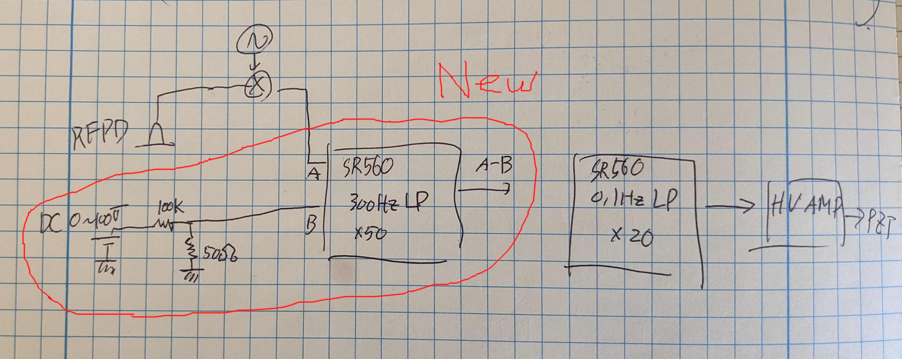
Better PDH servo (still a hack):
I changed the mod frequency from 60MHz to 40 by just looking at the error signal shape.
We used to use just one SR560 without any offset adjustment, with a single pole at 0.1Hz as a servo filter. The gain was increased until it starts oscillating by hitting PZT resonance, and then dialed back.
I added SR560 to amplify the error signal, subtract DC offset and add a pole at 300Hz at the same time. The additional pole would allow increasing the DC gain w/o hitting the PZT resonance, it also helped filtering out high frequency components that are otherwise sent to the HV amplifier. With more stable RFAM, DC offset subtraction means that we can fine tune the lock point.
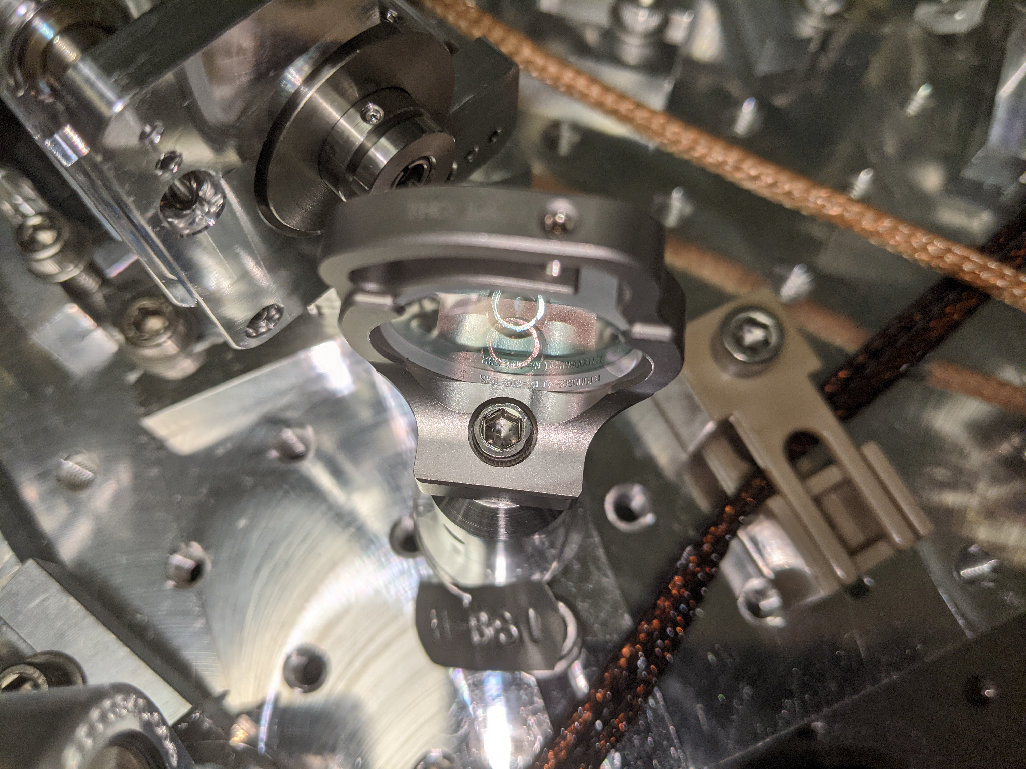
See the cartoon.
4. Setting up retroreflector for A path.
A retroreflector was placed 181mm away from A:M3 and was roughly aligned. The reflection is going through the Faraday and making it to the B path, but it's not perfectly retro-reflecting. Will work on it next week.