This morning Georgia and I retook some data points from alog 59341 as after Keita's power meter work (59372) we felt we were not careful enough with power meter centering and angle. This time we centered the beam on the power meter and checked the beam reflected off the power meter was aligned using a low intensity IR beam card with a hole punched into it. This should give us a angle accuracy of ±1°.
Adjusted power to have 40mW input into in-air fiber. Didn't measure output of in-vac fiber. Applied 136mA to TEC to get 10.29kOhm.
Below and attached is the data taken.
In the afternoon Keita and I continued investigating the SFI1 throughput.
- We noted that the beam height is 64.5mm before and after SFI1 - it seems quite flat but about 1mm higher than design (2.5")
- We angled A:M2 down very slightly to make the beam 2.5" after SFI1
- We remeasured the SFI1 transmission and found it to be 93% (see data below)
- We fixed the alignment of A:M2, checking carefully that the beam really was retroreflected back along the B path
- We measured the transmission of the SFI to be 107% (see data below). The measurement of the incoming power seems suspiciously low, even though we have been very very careful with power meter position and angle.
Data when beam was adjusted to be tilted down slightly through SFI1:
| PM power [uW] | PM dark [uW] | PM voltage [mV] | Reference voltage [mV] | Reference dark [mV] | P_scaled | |
| Input to AP1 | 618 | 38.7 | 2100 | 46.6 | 0.282 | |
| SFI1 output | 597 | 24 | 199 | 2230 | 46.2 | 0.262 |
Data when beam was at nominal posiiton through SFI1 (1mm too high, but the position we've aligned the B and H paths too)
| PM power [uW] | PM dark [uW] | PM voltage [mV] | Reference voltage [mV] | Reference dark [mV] | P_scaled | |
| Input to AP1 | 588 | 16.5 | 196 | 2550 | 46.5 | 0.228 |
| SFI1 output | 640 | 26 | 213 | 2550 | 45 | 0.245 |
Today we made final measurements of the SFI1 and SFI2 transmissions, as well as the SFI2 isolation. We measured ~100% transmission through SFI1 and SFI2. We measured 29.6dB isolation from SFI2.
SFI1 transmission
- We aligned the power meter by first centering the beam on the sensor, and then ensuring the sensor was perpendicular to the beam by looking at the reflection off the power meter face and tracing it back ~30cm along the beam path. We overlap the refleciton and the incombing beam using the sensitive Thorlabs card with a ~1.5mm diameter hole punched through it.
- By adjusting the AOI of the power meter to be ~2.5 degrees we could increase the measured power (which agrees with Keita's measurements last week). However this was much less repeatable and precise than getting the AOI to be ~0 degrees at every position along the beam.
- The SFI1 thermistor was at 10.47 kOhms for these measurements, nominally it should have been 10.3 kOhms
- The total transmission of SFI1 was 100.1%. We estimate +/-1% uncertainty on our measurements. Table of data below:
| PM power [uW] | PM dark [uW] | PM voltage [mV] | PM voltage dark [mV] | Reference voltage [mV] | Reference dark [mV] | P_scaled | |
| Input to AP1 | 593 | 4.8 | 197 | 1.35 | 2600 | 36.7 | 0.229 |
| After AP1 | 581 | 3.2 | 193 | 0.4 | 2605 | 35.9 | 0.225 |
| SFI1 output | 594 | 5.1 | 198 | 1.26 | 2600 | 35.7 | 0.230 |
SFI2 transmission
- We then switched the isolator TEC control to SFI2 and measured the path leading up to SFI2 and the SFI2 transmission.
- We accidentally set the current a bit high, and for these measurements SFI2 thermistor was at 9.3 kOhms. I don't think the effect of the TEC was large enough to matter for our measurements.
- We measured 100% or 99% transmission through the elements leading up to SFI2 (B:L1, B:M1), and 100% transmission through the isolator. The leftmost column in the table below is the two elements the power meter head was placed between (diagram for reference).
- We measured 97.3% transmission between B:M3 and B:M4, which checks out since there is a 99:1 beamsplitter on this path. We looked for the transmitted beam from the forward-propagating path but could not find it with the card and viewer.
| PM power [uW] | PM dark [uW] | PM voltage [mV] | PM voltage dark [mV] | Reference voltage [mV] | Reference dark [mV] | P_scaled | |
| AP1-BM1 | 489 | 15.5 | 163 | 3.8 | 2600 | 37.8 | 0.1848021232 |
| B:L1-B:M2 | 497.5 | 30.7 | 166 | 9.8 | 2585 | 40 | 0.1834184676 |
| B:P1-B:F1 | 477.5 | 10.4 | 159 | 2.75 | 2560 | 40 | 0.1853571429 |
| B:F1-B:M3 | 302 | 12 | 101 | 3.8 | 1610 | 40 | 0.1847133758 |
| B:M4- | 292.5 | 9.6 | 98.1 | 2.4 | 1615 | 40.1 | 0.1796304527 |
SFI2 isolation
- Finally we set up the isolation measurement. We aligned an auxiliary s-polarization path backwards through the isolator, using an iris just off the VOPO platform and one between B:F1 and B:P1 which we set up for the forwards-propagating beam.
- We measured the power transmitted through B:L1 and the power entering the isolator just after B:M3
- We measured 29.6dB of isolation, data below:
| PM power [mW] | PM dark | P-P_dark | |
| SFI2 input | 16.3 | 1.01E-02 | 1.63E+01 |
| Through SFI2 on main path | 2.09E-02 | 3.00E-03 | 1.79E-02 |
I kept the data in a rough spreadsheet here.
The above alog 59384 is the only power measurement with a stringent condition consistently set for power meter AOI. Prior measurements may be OK but they're not consistent with alog 59384 so we won't use them.
Remaining tasks, roughly in chronological order, are:
- Setting up B:M5 using backwards-injected beam.
- Repeat the previous measurement (59352) for the splitting ratio of 90:10 splitter in the FC path (for retroreflector and DC monitor), but this time making sure the Ophir sensor retro-reflects using a card with 1.5mm hole.
- SFI1 transmission measurement with the temperature not optimized.
- Measurement of overall transmission (i.e. measure between OPO and A:DC1 as well as downstream of B:M4), SFI1 temperature not optimized, SFI2 temperature optimized.
- Since we moved the SFI1 transmission alignment once (see Gerogia's alog above) and recovered the alignment using one of irises we set up on VOPO platform, we need to confirm that the green beam from H path is still coaligned with the IR beam from A path, and if not we need to adjust H path.
- Swap the IR retro reflector in FC path with the green one and set H:M4 up.
- Telecon with others and confirm that people are happy.
- (Optional but doable and beneficial: Adjust CLF mode matching to OPO by adjusting collimator and/or F:L1.)
- (Optional but doable: Measure the mode profile of green pump reflected by OPO. That path was already set up and the lens is at a nominal location.)
- Uninstall all temporary irises on VOPO platform.
- Install two aperture stops.
- Install SFI heater/thermistor cables and cable brackets.
- Balance SUS.
- Celebrate.
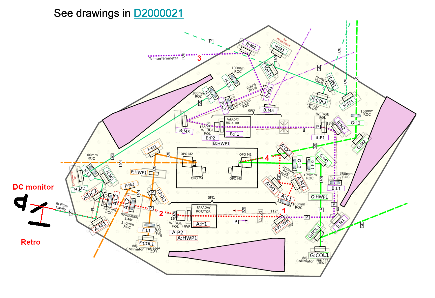
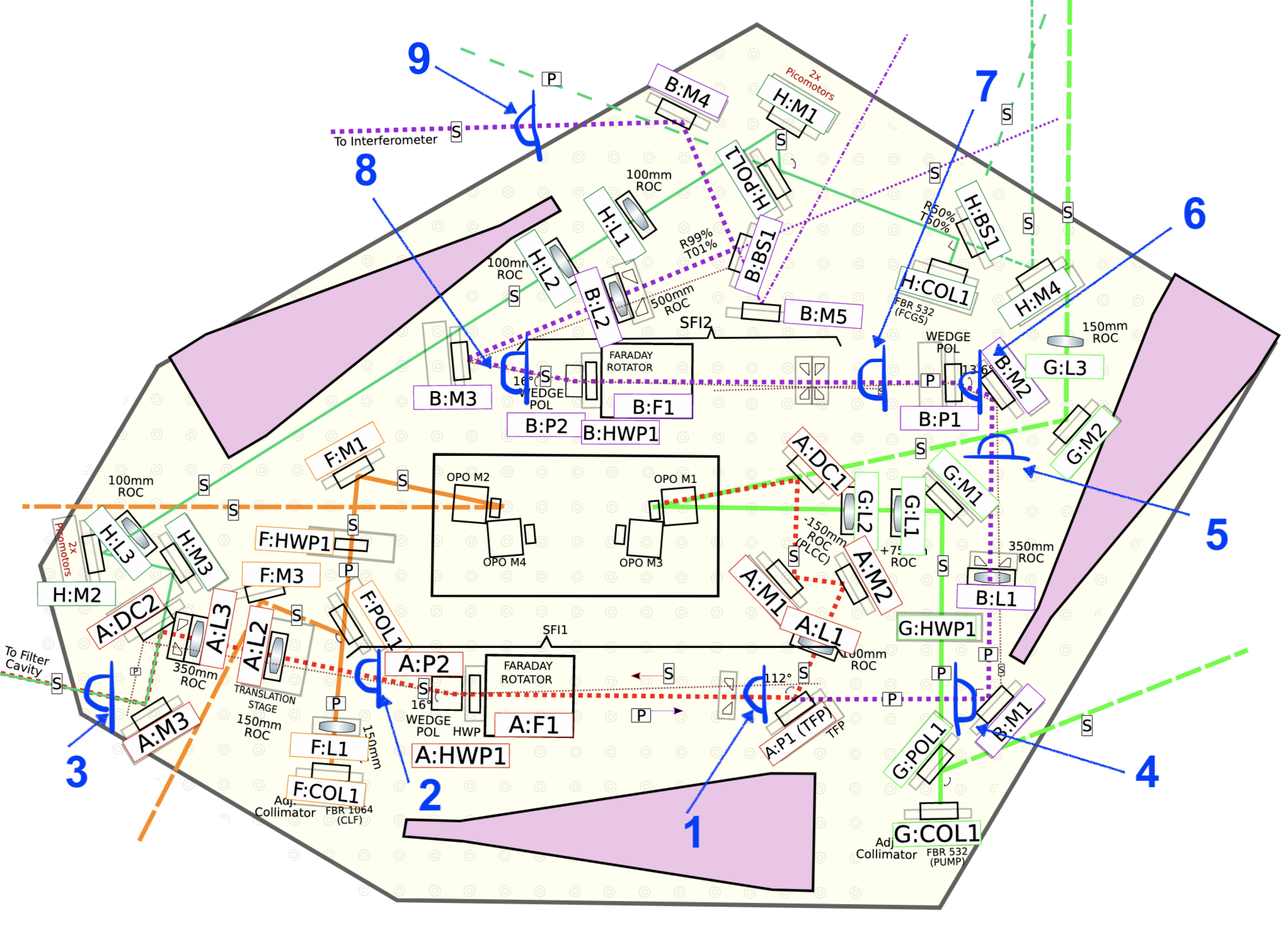
See the 1st attachment for layout and component name.
1. Setting up B:M5
Done by Camilla.
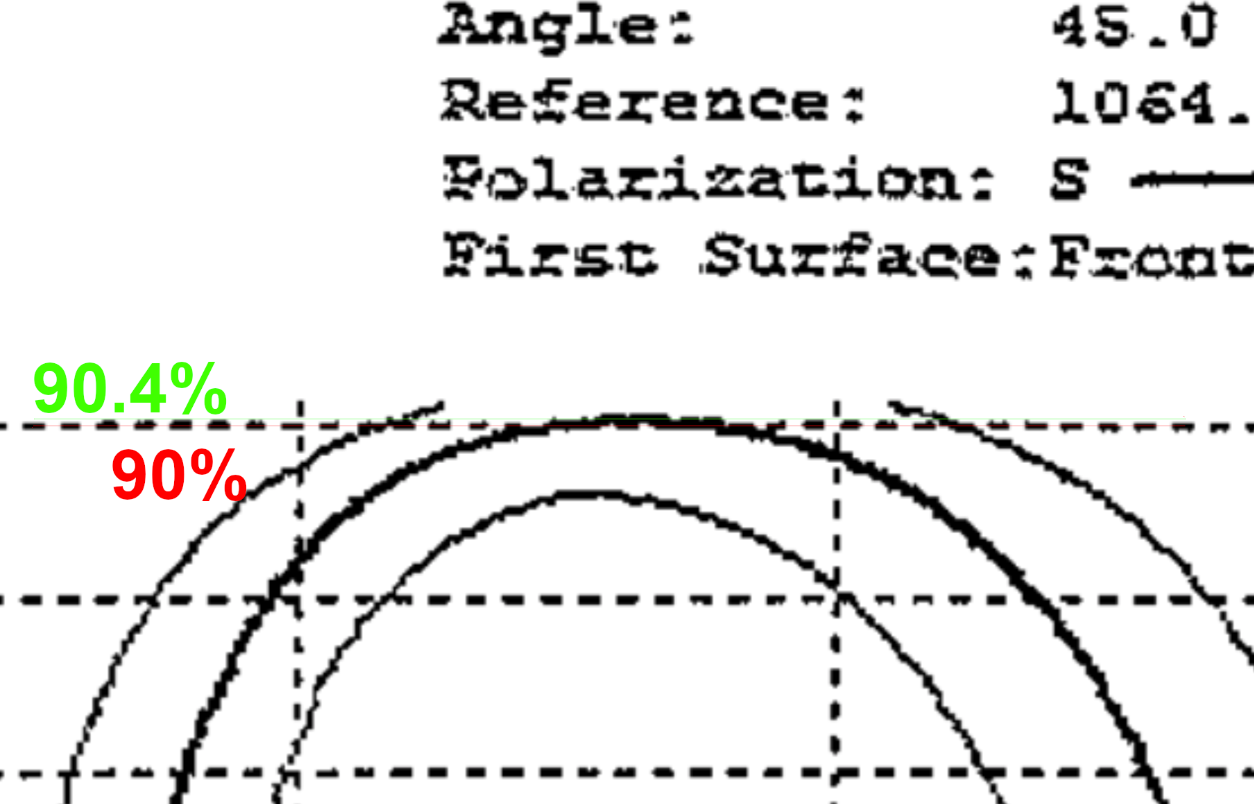
2. Remeasuring the splitting ratio of the external BS in front of the retro reflector using as good of AOI on the power meter as possible
We obtained 90.4:9.6. Detailed numbers are in the attached script. Note that this BS is E1700102 and AR is 0.1%, totally negligible compared with the accuracy of the measurement technique. Also, just for a laugh, look at manufacturer's data with my annotations (attached, but you need to magnify the image to see green and red horizontal lines I added).
3. SFI1 transmission measurement with the temperature not optimized.
Attempted, no good measurement yet. During the first attempt we found that there seem to be a spot(s?) on the power meter sensor that is particularly sensitive to AOI variation. See followup entry.
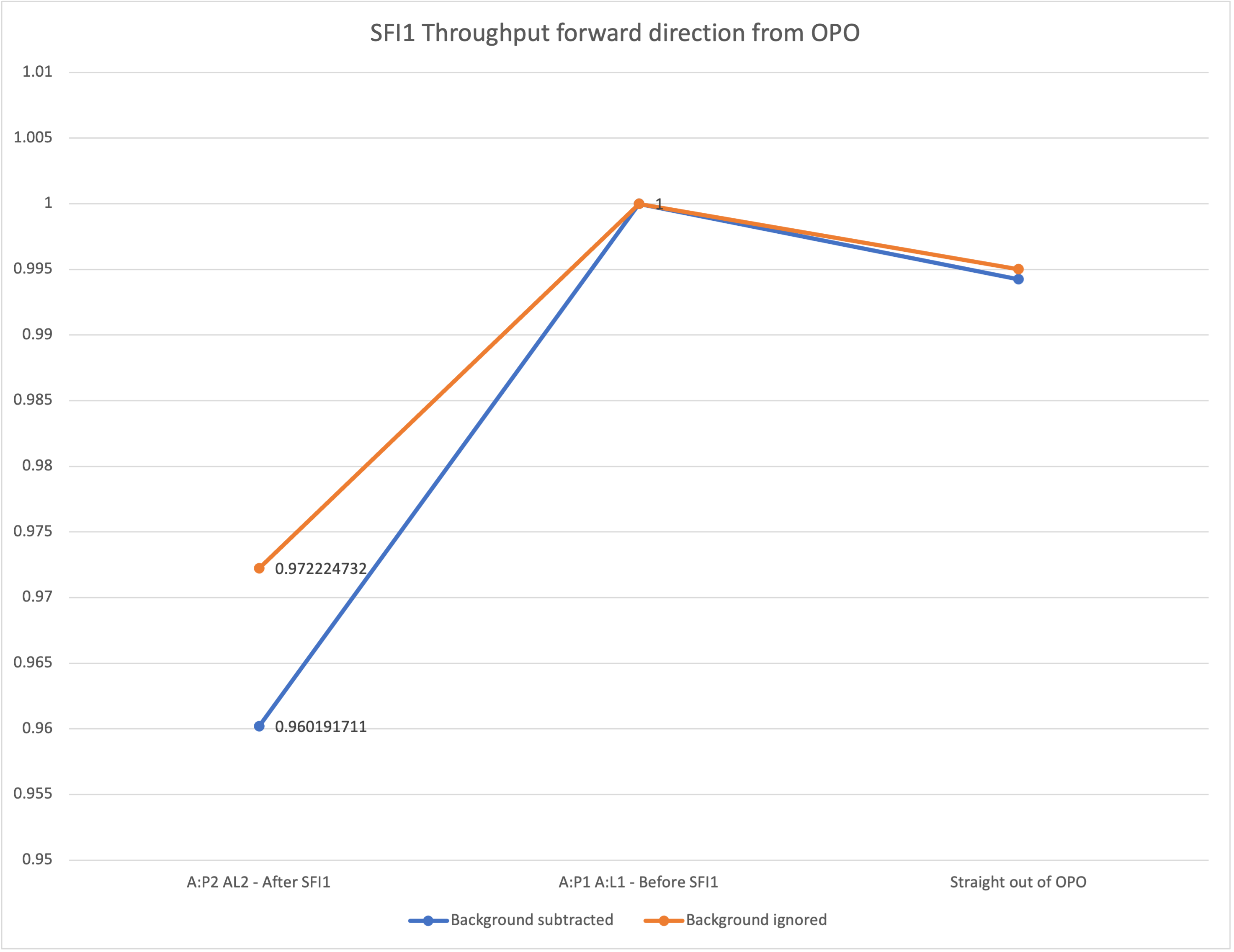
4. Measurement of overall transmission (i.e. measure between OPO and A:DC1 as well as downstream of B:M4), SFI1 temperature not optimized, SFI2 temperature optimized.
Half-done, but in our measurement both SFI1 and SFI2 temperature were at room temperature. SFI1 and SFI2 thermistor were measured to be 11.33Ohm at room temperature.
We first measured at point 1 (upstream of SFI1 where it's easy to set the AOI fairly accurately), then at point 3 (IFO path), then at point 4 (right after the beam comes out of OPO, hard to set the AOI accurately due to tight space).
|
Power meter voltage bright-dark (using fixed 3mW range) [RAW, Normalized] |
Power meter Watts bright-dark (3mW range for bright, 30uW range for dark) [RAW, Normalized] |
DC monitor diode bright-dark used for normalization (PDA100A, 40dB gain setting) |
|
| Point 1 | [270mV, 7.60e-2] | [809uW, 2.28e-4 W/V] |
3.55V |
| Point 3 | [208mV, 5.93e-2] | [628uW, 1.79e-4 W/V] |
3.51V |
| Point 4 |
[267mV, 7.66e-2] |
[799uW, 2.29e-4 W/V] | 3.48V |
We recorded both the voltage output and the power reading out of the power meter. The analog output is convenient to record at the same time as the DC monitor diode, but the power meter reading with automatic range might give us a bit better background (dark) power if we trust the meter's relative calibration across its range. Problem with using auto range together with analog voltage is that I don't know if the gain scales with the "range" number (it should but I didn't want to measure).
Throughput from the input of OFI1 to the IFO path using the power reading is (1.79e-4/2.28e-4)/(R_BS^2)=95.8%
where R_BS is the reflectivity of the external BS (90.4%).
Overall throughput from OPO output to the IFO path using the power reading is (1.79e-4/2.29e-4)/(R_BS^2)=95.3%.
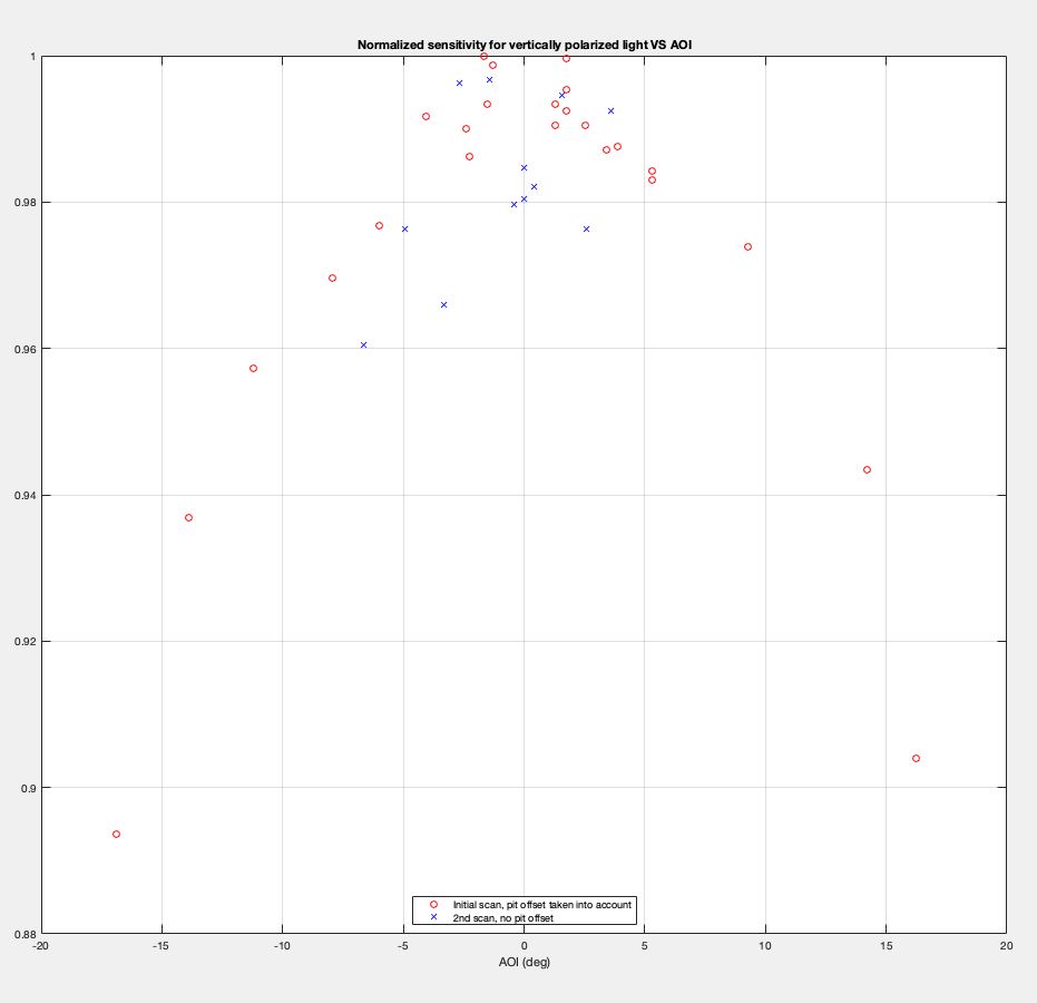
Note that we're not claiming .1% accuracy as the accuracy of each power measurement is somewhat worse than +-1% or so (even though AOI is exactly the same there's a beam position dependence, which was measured to be +-1% unless the beam is on a "bad spot").
All data points are here: google sheet
Due to the lessons learned in 3:, we offset the beam position from the center, and scanned the AOI by a large amount to see if there's a steep AOI dependence.
4': Orientation of all important optics were checked to be good.
We've checked the orientation of all important optics in A and B path.
For A:DC1, we looked at the distance between the incoming and the reflected beam using the OPO transmission. It was about 3~4mm at the front surface of the optic mount, i.e. about twice as the distance from the surface of the optic mount to the optic surface. Good.
For A:M1, A:M2, A:P1 (TFP), A:DC2, A:M3, B:M1, B:M2, B:M3, B:BS1and B:M4, we hit them using an external IR laser beam to see the AR reflections.
