TJ, Craig, Camilla, Varun
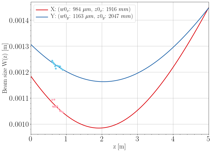
Setup: We powered the NPRO laser with help from Jason. The beam quality was poor when the driver current was low. Therefore, we decided to operate at 2W of output power. The volume control using a series of quarter wave plate, half wave plate and a polarizing beam splitter was used to adjust the power required for the measurements. We beam was then picked off with a HR mirror. Two steering mirrors were setup to align the beam parallel to the table and co-aligned along the length of the table. Next, we took some beam profile measurements to access beam quality, followed by extending the beam waist to 2m by setting up a telescope. The final beam profile is shown in the plot below. Lastly, before introducing the OFI we introduced an end mirror to retro reflect. The reflected beam was aligned with the input beam. This was done as a good starting guess for mirror position to send the reflected beam back through the OFI after it's installation.
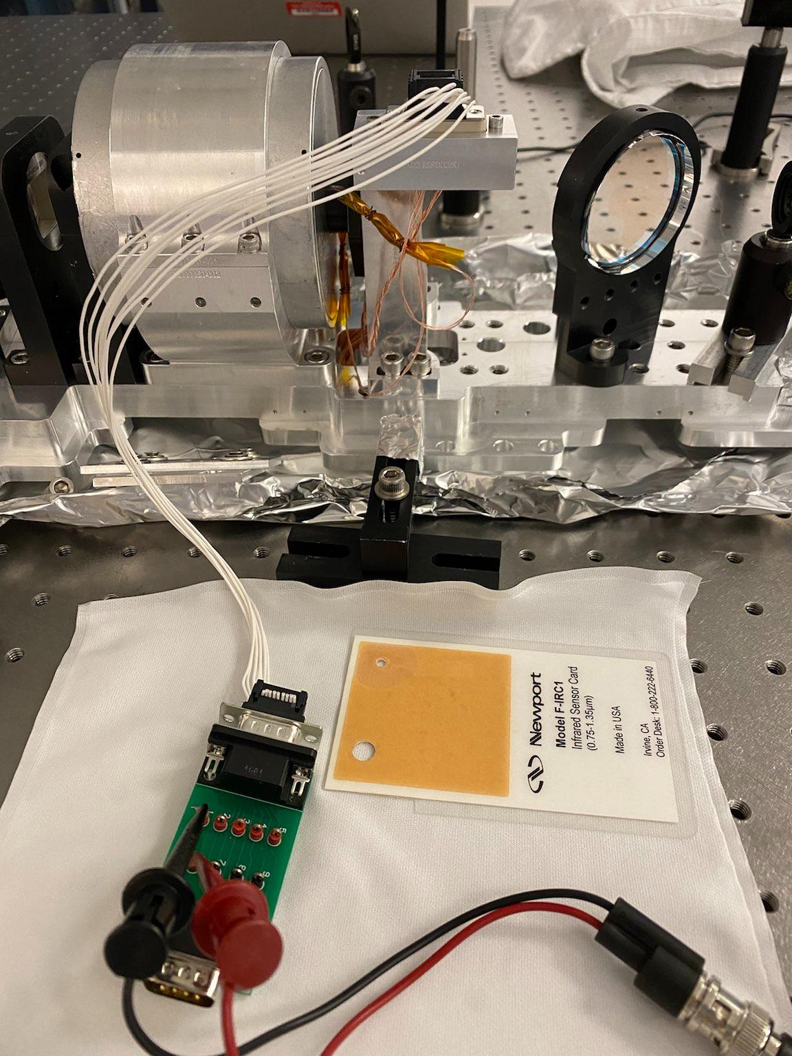
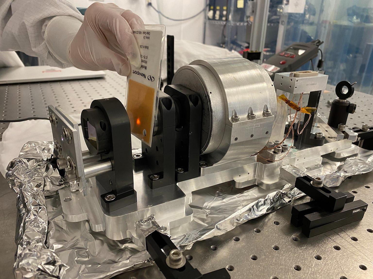
Next, we introduced the OFI into the setup. The OFI height was adjusted with 1 inch" pedestals and clamped down on the optics table. The final setup of the table is shown in figure. We have a slight tilt in the OFI installation which we suspect may be introduced because of the aluminum foil under the OFI present to ensure it is clean. The input beam was aligned to then maximize the throughput power at the output of the OFI. We then did the three tests
IFO to OMC throughput: We did 5 measurements and get an estimated averaged throughput of 99.2%. With an average of 33.64 mW of input power and 33.34 mW recorded in transmission of the OFI.
IFO to Squeezer Isolation: With five measurements, we measure an approximately 8.3 muW of power for the p-beam (confirmed with a PBS) towards VOPO for 36.4 mW of input power. This corresponds to an IFO to SQZ isolation of 36.4 dB.
IFO backscatter isolation: We were having a difficult time trying to find the beam, so for the first set of measurements we purposefully misaligned the retro reflector mirror. In this alignment, the reflected beam was pitched higher. We took a rough measurement of the power and estimated only 27 dB of the backscatter isolation. We will work on improving the alignment and then remeasure to get a better estimate of the backscatter isolation.
TJ, Daniel, Varun
The image of the setup is shown in figure and is similar to the one in G2100316. Also, I missed adding that the beam waist is at approximately 2m after the last steering mirror. We then re-tried the measurement of backscatter isolation for the OFI by tweaking the alignment. We also note that the low beam intensity requies measurement in the dark after calibrating the power meter.
IFO backscatter isolation: We added another PBS bigger at the input. This setup has the caveat that the backscatter isolation is estimated only for the S-polarized beam. The previous beam splitter was small and made it difficult to see and align the weak reflected beam. Again, misaligning the beam in pitch made the reflected beam clearly visible on the IR card. In this configuration we coaligned the reflected beam in yaw to match the input beam. The pitch was then aligned. We measure a ~2.3-2.5uW beam at the PBS coming from the reflection from the retro reflector. We also blocked the path from the reflector to verify we were looking at the right beam. We measured 37.2 mW of input power and with five measurements estimate 39 dB backscatter isolation under the assumption that the S and P polarized beam have equal amplitudes.
Summary of OFI Tests: The design requirements are taken from T1900788 and G2101056.
| Test | Design Req. | Measured |
| IFO to OMC throughput | >99% | 99.2% |
| IFO to Squeezer Isolation | >30 dB | 36.4 dB |
| IFO backscatter isolation | >30 dB | ------ |
We will replace the PBS introduced and redo the measurements using a P-beamsplitter to estimate the IFO backscatter isolation.
Craig, Georgia, Varun On Monday, Varun and I added a new 50:50 P-polarized beamsplitter into the OFI path. Then Georgia and I realigned the beam through the OFI by removing the mode matching lens, aligning through the OFI with the steering mirrors, then re-inserting the lens at the same location to keep a beam radius of around 1 mm through the entire setup. The rejected beams are dumped on beam dumps or irises. The labeled setup is shown in the first attachment. We then started verifying the OFI performance, according to the first three measurements in G2100316 For all measurements, the slow power drift of the laser was monitored via a fixed power meter at the reflection of the P-pol BS. Care was taken to try to maximize the power meter output and keep a consistent angle on the power meter between measurements to avoid retro-reflection. Still, it is difficult to measure power to better than 1% consistently with the Ophir power meters. So, 1% is the assumed uncertainty for every power measurement taken. First, we measured the beam splitting ratio of our P-polarized BS. In all cases, slightly more light than 50% was reflected:Meas BS (P) Refl 1) 0.5252 2) 0.5189 3) 0.5249 4) 0.5469 Weighted average of BS (P) Refl = 0.5286 +- 0.0037Second, we measured the OFI throughput (from IFO to OMC) ratio. The power at the input to the OFI was measured, then in transmission. The polarization of the transmitted light was checked with a PBS, and was found be to extremely good (~0.999 P-polarized).Meas OFI Throughput 1) 0.9804 2) 0.9846 3) 0.9807 4) 0.9926 5) 0.9913 Weighted average of OFI Throughput = 0.9859 +- 0.0062Third, we measured the IFO to SQZ isolation ratio:IFO to SQZ isolation = 10 log(P-polarized power reflected off TFP / Power input into OFI)Meas IFO to SQZ isolation [dB] 1) -37.1 2) -35.1 Weighted average of IFO to SQZ Isolation = -36.0857 +- 4.5725 dBFinally, we measured the OMC to IFO isolation ratio:OMC to IFO isolation = 10 log(P-polarized power reflected off back of BS (P) / (BS Refl * Power in transmission of OFI))Meas OMC to IFO isolation [dB] 1) -37.2 2) -36.1 Weighted average of OMC to IFO Isolation = -36.6948 +- 5.1063 dBSummary The isolation appears to be very good, even in the worst case that all non-rejected light is in the P-polarization. It's hard to verify the OFI throughput > 0.99 with our current power meter setup. Basically all of the light in transmission of the OFI is in P-polarization, meaning the quartz rotator and big magnetic rotator are working well. To Do: 1) Check the polarization of the isolation beams. 2) Put power meter on a rotating mount. Data and code lives here: https://git.ligo.org/craig-cahillane/output_faraday_isolator_verification

Craig, Varun

Today we measured two aspects of the OFI:
1) the IFO to OMC isolation beam polarization, to make sure we were measuring the correct beam,
2) the OFI throughput over several different angles in yaw using a setup similar to Keita's in alog 59372.

Results
1) The OMC to IFO isolation beam is at least 98% P-polarized.  We tested this by putting a PBS in the beam path with the lights off and rotating it around to maximize throughput.  The reference beam was dumped to minimize the significant scatter it caused.

2) The OFI power throughput was estimated to be 0.990 +- 0.005.

We found that spurious internal reflections and retro-reflections were a problem for our absolute power measurements using the Ophir Vega power meters.
To control for these "spurious" high and low power readings, we decided to try to control the sensor head angle in a measurable way.

This was done by securing a Ophir Vega power meter head (with filter) to a rotating mount, as seen in the first attachment.
This gave us precise control over the yaw angle of the sensor head.
The beam was centered on the power meter as best as possible, then the yaw angle was swept in increments of 2 degrees.
The reference power pickoff of the laser was accounted for in all reported measurements.

This process was done for both transmission through and input into the OFI.
A quadratic was then fit to the data, including fit uncertainty via the covariance matrix.
The fit acts to smooth over some spurious power measurement artifacts.
The results are in the second and third attachments.

The max estimated OFI transmitted power was 39.97 +- 0.20 mW
The max estimated power input into the OFI was 40.38 +- 0.06 mW

Together these give the OFI throughput estimated above, with about a factor of two improvement in the uncertainty compared to the previous alog 59439.

-------------------------------------------------------------------------------------------------------------------------------------------------------------------

The results of this alog and alog 59439 demonstrate that the OFI is operating as expected, according to requirements.
We believe that the OFI is ready for install in HAM5.
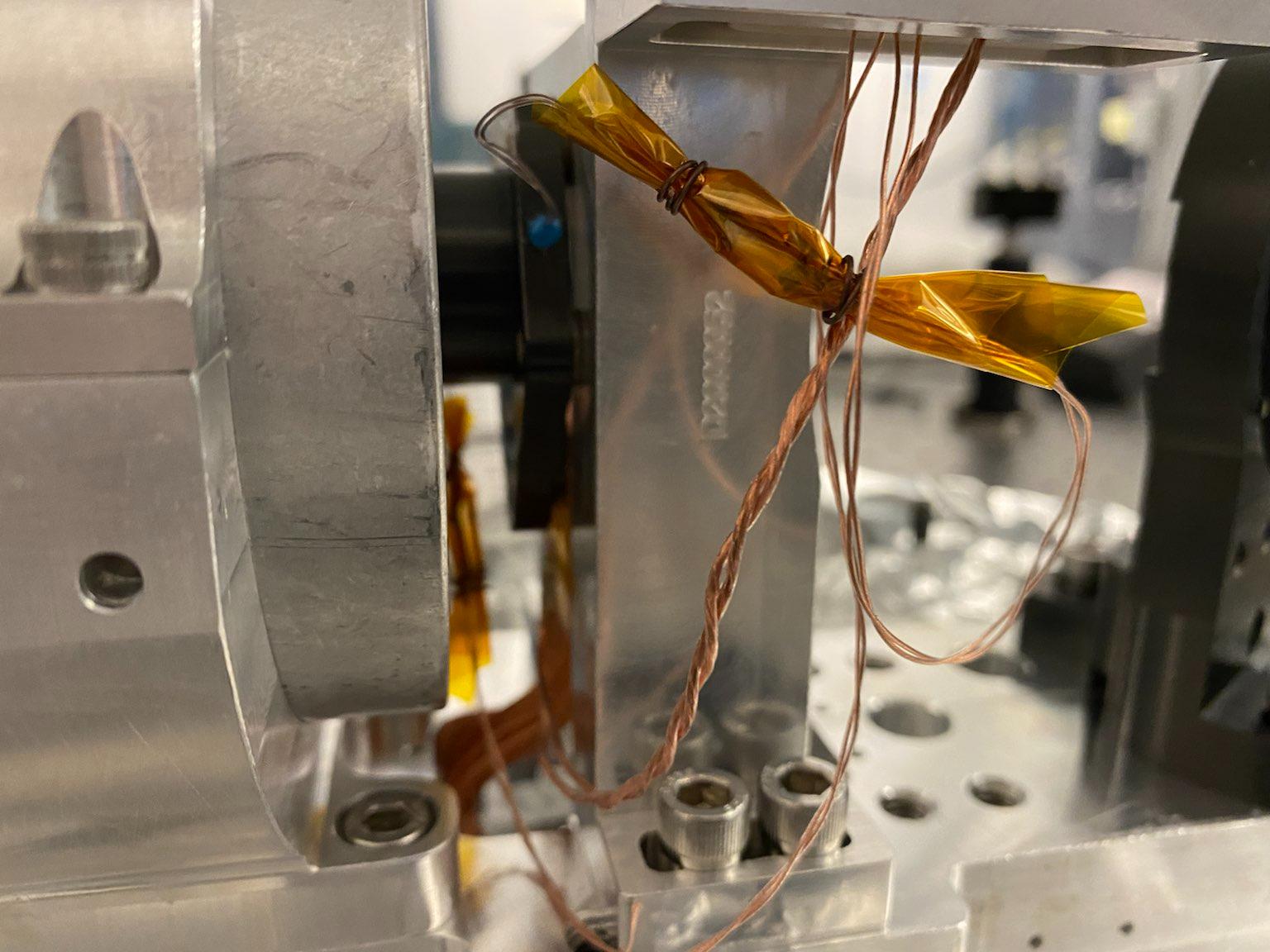
Craig, Georgia

Electronics testing of the OFI

No shorts from any of the 6 available pins on the D9 connector to ground.
No shorts from any of the 6 pins to each other.

Optics lab room temperature at time of measurements 69 degrees Fahrenheit.

Resistance of thermistor one (pin 1 to pin 6) is 11.17 kohms.
Resistance of thermistor two (pin 2 to pin 7) is 11.15 kohms.

We believe these where the settings under which all previous power measurements were made.


Test drive of peltier

We ran 100 mA to the Thermo-Electric cooler that's mounted on the OFI Faraday rotator to remotely control the non-reciprocal rotation from the magnet.
We got resistance of thermistor one down to 10.74 kohms.
This corresponds to 0.3 volts between pins 1 and 6.

Front Aperture put back on
We put the metal front aperture back on as best we could.
We maximized light was getting through the aperture to the OFI.

The back aperture is a bolted-down iris on the OFI itself, and was never moved.

The way the aperture is set up, we only had control over the height of the aperture.
This means the yaw alignment is still the alignment from Florida, but the pitch alignment is from the LHO optics lab.
In any case, this will help the HAM5 install team with coarse alignment to HAM7.

Also, Paul Fulda has posted the Florida test results of the OFI on the DCC: https://dcc.ligo.org/LIGO-Q2100031

These results were 40.8 dB isolation, and effective single-pass loss 0.85%.
This is slightly better than our results, but both are in agreement with requirements.