[Corey, Kiwamu]
We replaced the two broken infrared QPDs that were in the POP QPD sled at HAM3 with the new ones.
After the replacement we confirmed that the new QPDs works fine. From the ISC point of view HAM3 is ready for pitting the doors.
QPD swapping
The broken QPDs (SN#39 in QPD1 and SN#53 in QPD2) [1] were replaced with the spares. The list below shows which QPD mount has which diode after the replacement.
QPD1 = SN#20 (the one close to the west door)
QPD2 = SN#24 (the one close to the north door)
We accessed the HAM3 table from the west and north side. We followed the same in-situ replacement technique as we did at EY [2] so that we don't have to remove the whole thing but we just swap only their QPDs. The replacement operation went quite smooth and was much easier than the last time when we performed it at EY where the optical table was suspended and freely swung. After the replacement we tested the QPDs by three ways : photo-current check with a hand-held QPD tester, diode voltage drop test and signal chain test with dataviewer. The QPDs signal made sense when we used the hand-held QPD while the QPD was illuminated with a visible red laser pointer. The voltage drop across each segment was approximately 0.36 V which seemed healthy. We were able to see signals at the IOP of the ASC front end with dataviewer although the signals were spiky since there was no anti-whitening filter for them. (In fact there was even no ASC front end model which takes care of these signals). From these tests we are confident that the new QPDs work fine and conclude that this mission is done.
QPD inspection
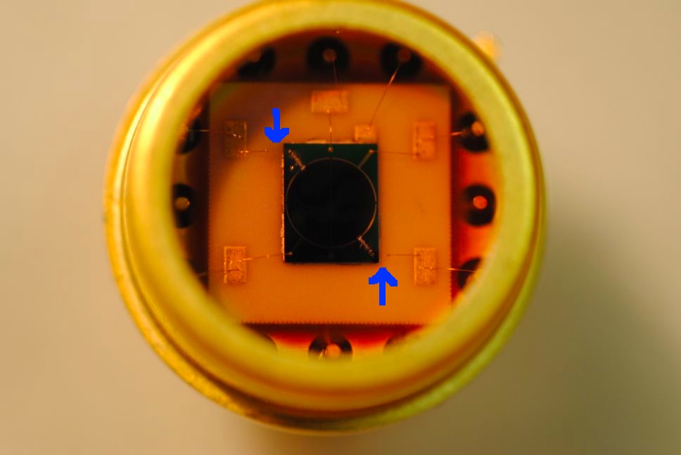
After the in-vac work we inspected the broken QPDs at the EE shop by inspecting the appearance and electrical characteristic. Filiberto looked at the QPDs with a magnifier and noticed that some of the wires were physically cut. The picture below shows a front view of one of the two broken QPDs. You can see that two wires, which are pointed by blue arrows in the picture, are cut. This is probably due to too much voltage (current) going through them when we were accidentally sending the picomotor driving signal which was more than 100 V due to the cabling error [1].
According to the electrical tests with a multi-meter, segment 2 and 4 of both QPDs are completely open as expected from the magnifier inspection. The rest of two segments are fine : they show 0.36 V voltage drop and the correct polarity. Note that this broken characteristic is different from that of the one we extracted from EY which was shorted [3].
Some notes
We fully removed the ISC-related tools from the HAM3 table so that we don't have to return to this chamber any more. However there was a thin metal plate left on the table which looked some kind of guard for the suspended mirrors. As we had no idea of what it was we left it in the chamber.
[1] LHO alog 5937 "HAM3 ISC IR QPDs are likely broken, in-vac cabling error, IO QPD should be OK"
[2] LHO alog 5718 "Comments on 'A new PZT mirror installed at ISCTEY and red in-vac QPD swapped on TMSY' "
[3] LHO alog 5942 " Broken infrared QPD of TMSY inspected "
| pin # | signal assingment in QPD cable (D1101624-v3) | signal assignment in picomotor cable (D1101516-v4) |
| 8 | QPD2 S | PM3 Y SIGNAL |
| 9 | QPD2 A2 | PM3 X SIGNAL |
| 10 | QPD2 A4 | PM2 Y SIGNAL |
| 11 | QPD1 S | PM2 X SIGNAL |
| 12 | QPD1 A2 | PM1 Y SIGNAL |
| 13 | QPD1 A4 | PM1 X SIGNAL |
| 20 | QPD2 C | PM3 Y RETURN |
| 21 | QPD2 A1 | PM2 X RETURN |
| 22 | QPD2 A3 | PM2 Y RETURN |
| 23 | QPD1 C | PM2 X RETURN |
| 24 | QPD1 A1 | PM1 Y RETURN |
| 25 | QPD1 A3 | PM1 X RETURN |
It looks that the reason why we had only segment 2 and 4 broken is due to the pin assignment.
In the above table you can see that the first half of the pins (of the DB25 cable) are assigned for segment 2 and 4 while all of them is populated by the picomotor SIGNALs in the case of the picomotor cable. On the other hand the 2nd half is shared by segment 1 and 3 where there is only RETURNs in the picomotor. When we looked at the picomotor signals from the control box using a breakout board the RETURNs didn't show any signals and hence I believe they behave more like ground in this setup. I guess we sent too much current on only these SIGNAL lines, resulting in melt of the wire in segment 2 and 4 while segment 1 and 3 survived because they are connected to RETURNs.