J. Oberling, R. Savage, V. Srivastava, J. Driggers, N. Patel, P. Thomas
Big push on wiring/cable routing and plumbing this week, thank you all for your help.
We removed the remaining extraneous cables from the PSL rack, primarily LEMO cables that are not used with the new laser. The purple cables (communicate with the PSL AA/AI chassis in the CER) were formed into bundles and excess length was pulled up into one of the cable trays above the PSL/ISC racks (where the rest of the excess purple cable lengths are looped back on each other). Since there are many cables for which we need to pull extra length out of the PSL enclosure, we reorganized the rear of the PSL rack a little to make that easier, untangling cables that were looped around each other and tying any extra length out of the way.
We then moved into the PSL enclosure and audited the cables in there, removing any unused ones we found that had not already been removed. Rick and Varun built some platforms for the new diode boxes; these were placed and the amplifier/diode box cooling loop was plumbed. The DBB was placed on the table. Extra length for cables we were using was pulled out of the enclosure and we roughly routed these cables along the floor in the general direction they were to go (i.e. the FSS TPD cables went to the North out of the cable walkover, as that's where the FSS Trans PD is located w.r.t. the cabl walkover, while the DBB cable bundle went to the south).
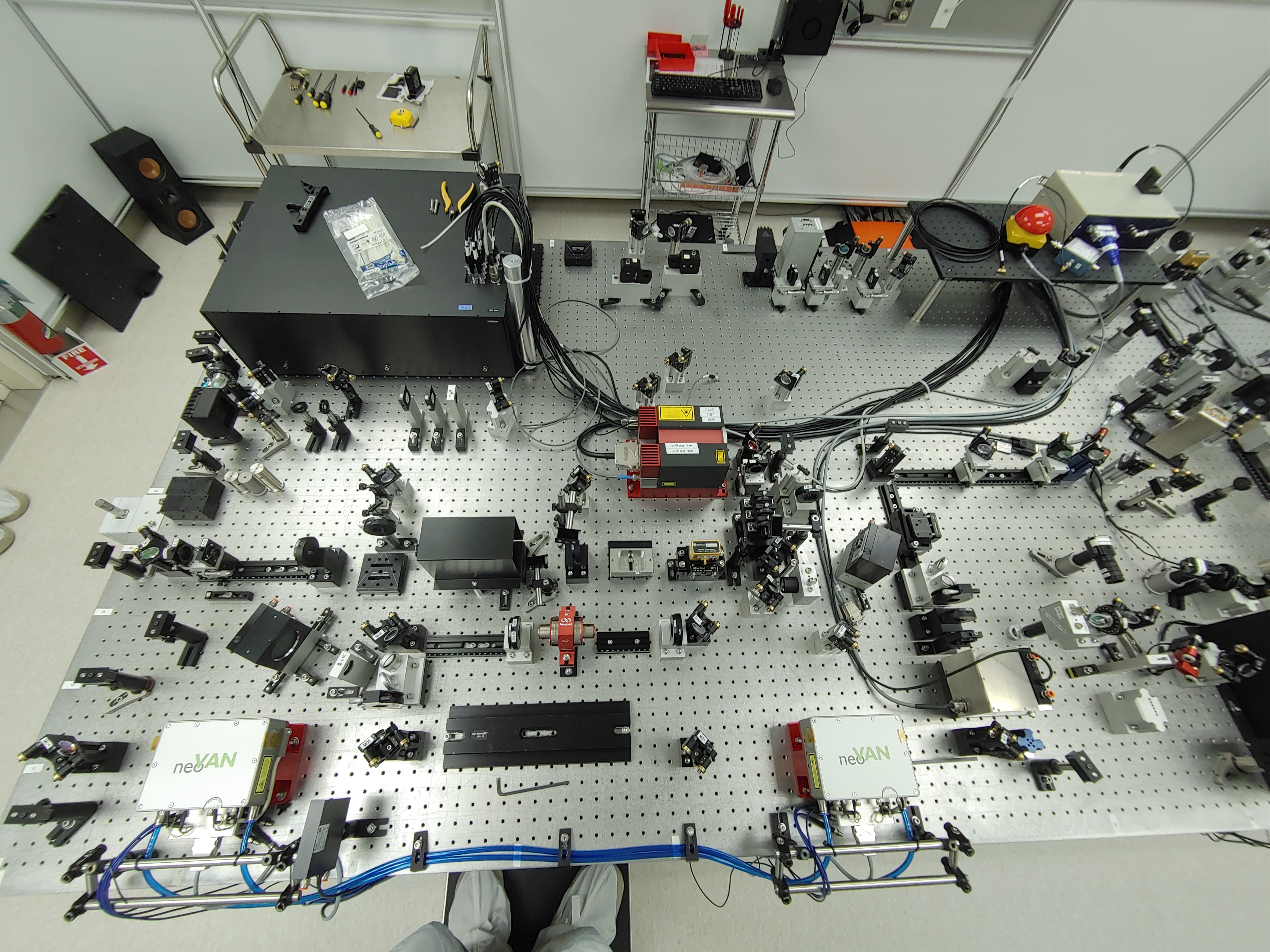
All of the components for the new laser were placed on the table in their locations to aid in cable routing and wiring. Except for the optical components between the NPRO and first amplifier, these components have not been aligned yet, some are missing their optic (for example, not all waveplates were installed, mirror M10 needs to be swapped), and none of the mode matching lenses have been installed (excpet for the first pair for mode matching the NPRO beam to the first amplifier). With these in place we ran a few cables to test out a couple of different routing paths (DBB bundle, shutter cables, NPRO cables). A platform was built for the TTFSS box, the small summing box that provides the 35.5MHz signal for PMC locking and fast phase corrections for the FSS, and the PD power distribution boxes and placed in the empty space on the table near the FSS path. This will greatly reduce the length of the FSS cables, especially the critical cables from the FSS RFPD, the NPRO PZT, and phase-correcting EOM (EOM01 on the proposed layout). The extra cable length pulled out of the PSL enclosure was dressed in the rack and organized.
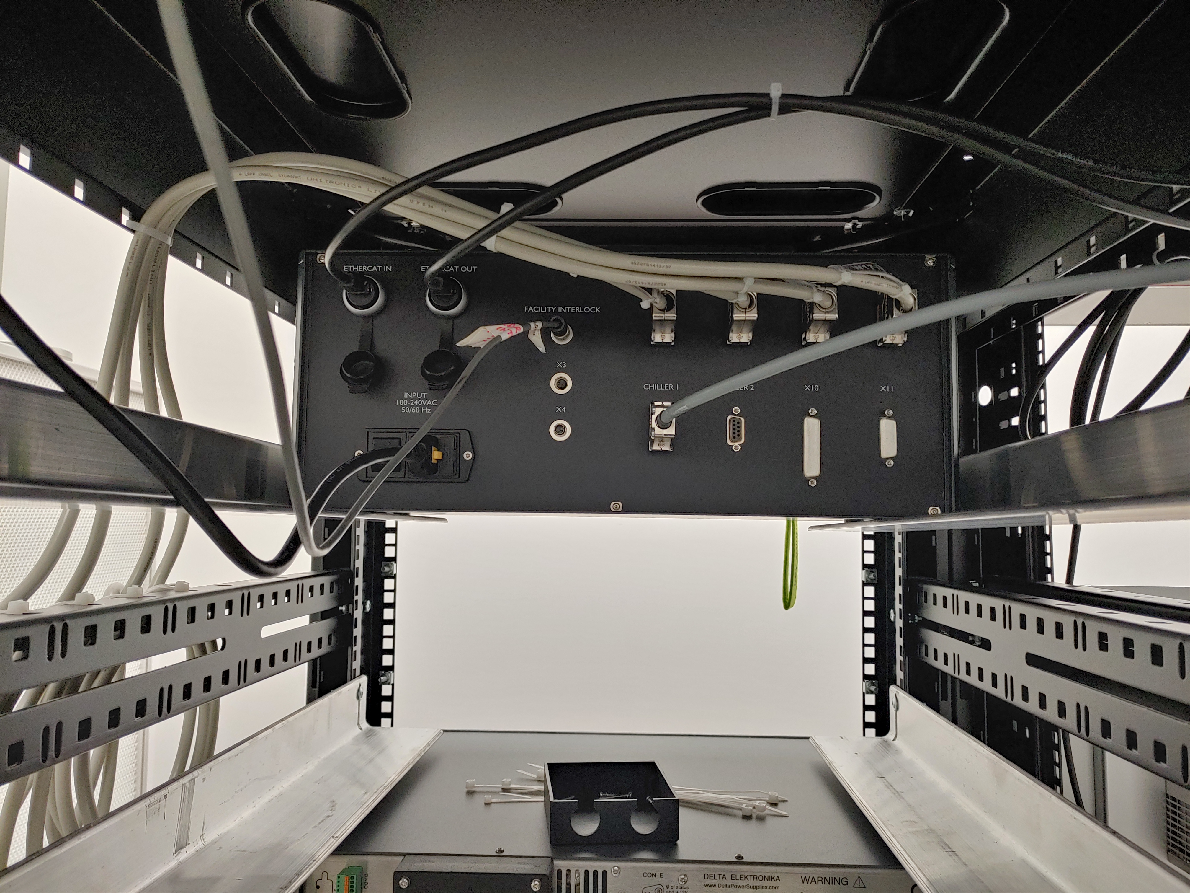
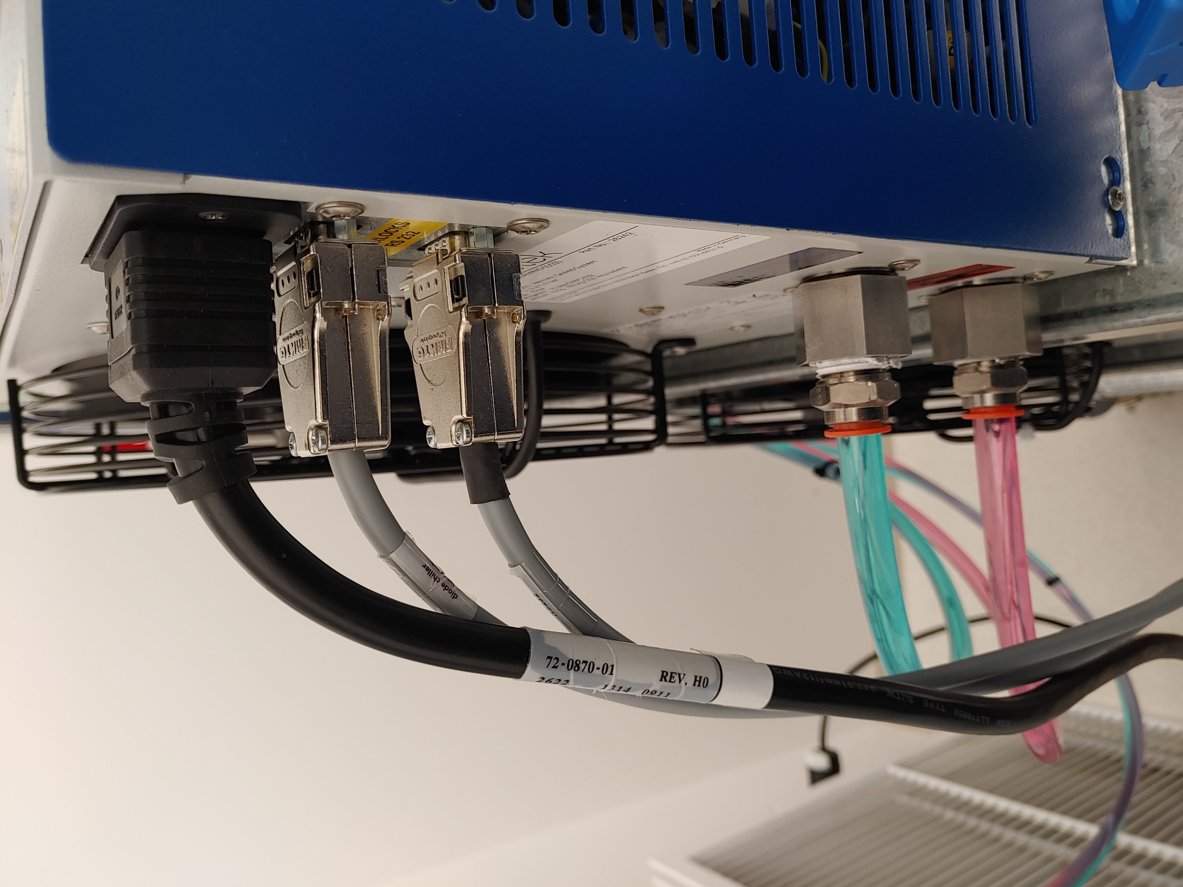
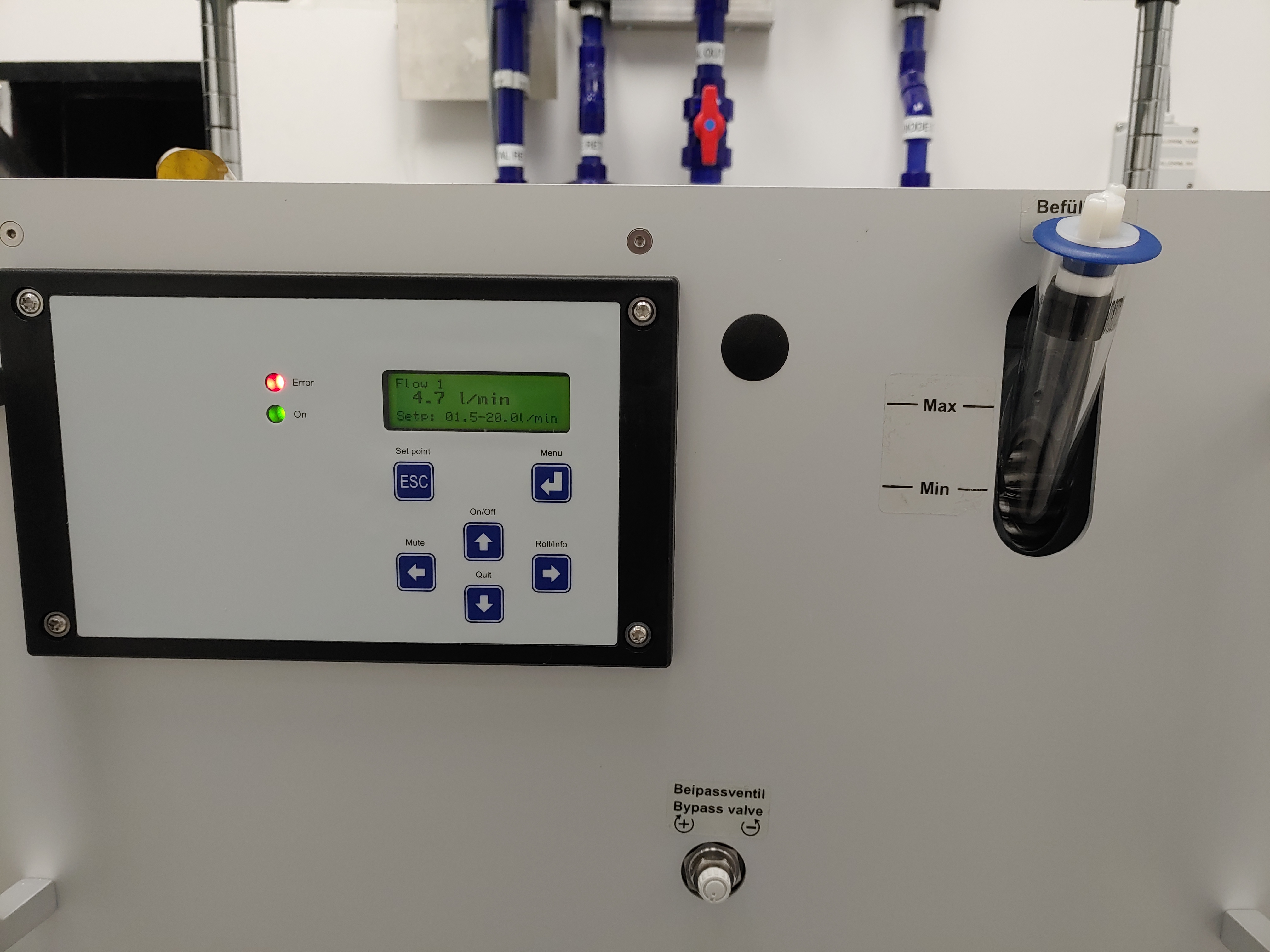
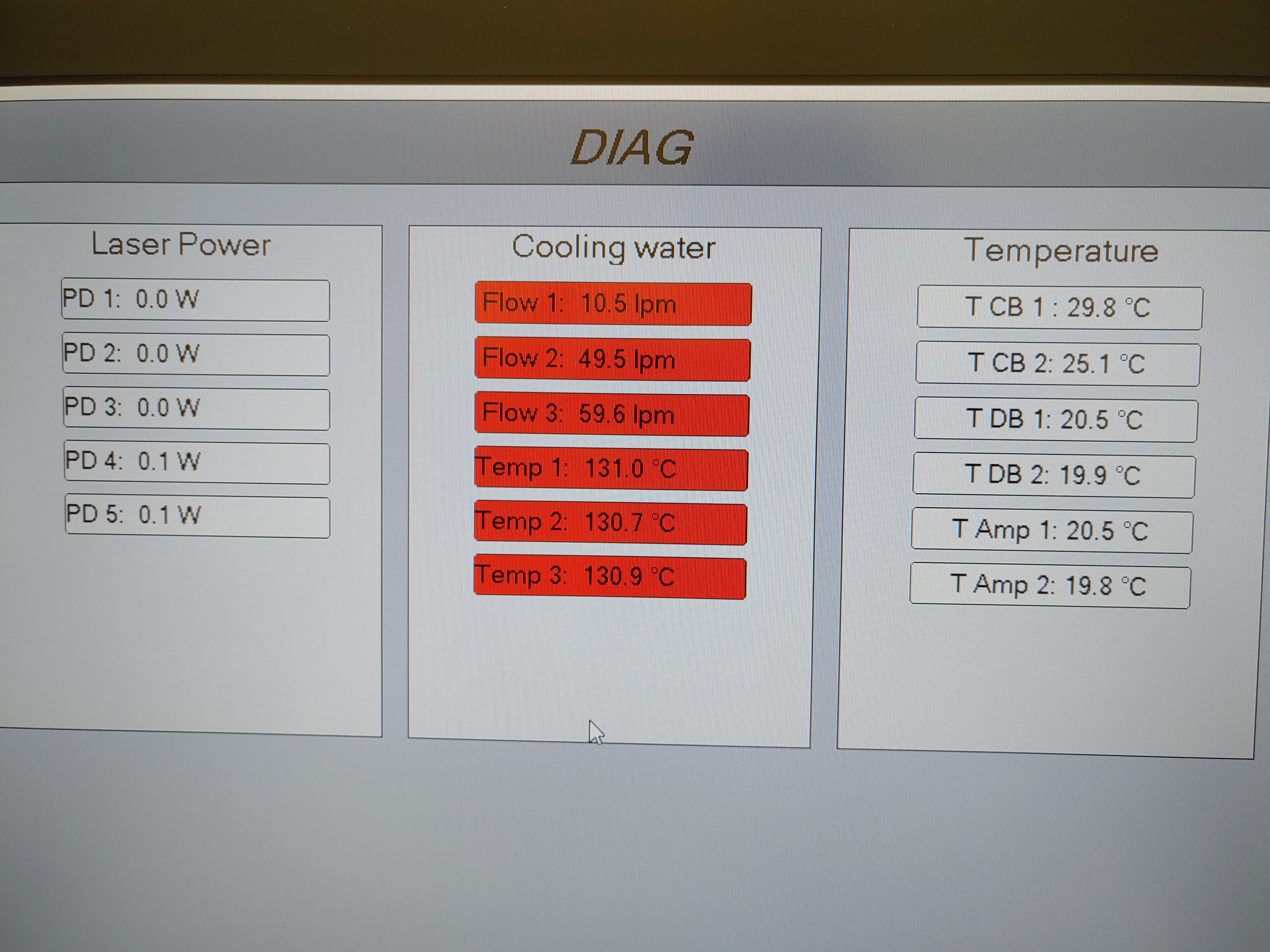
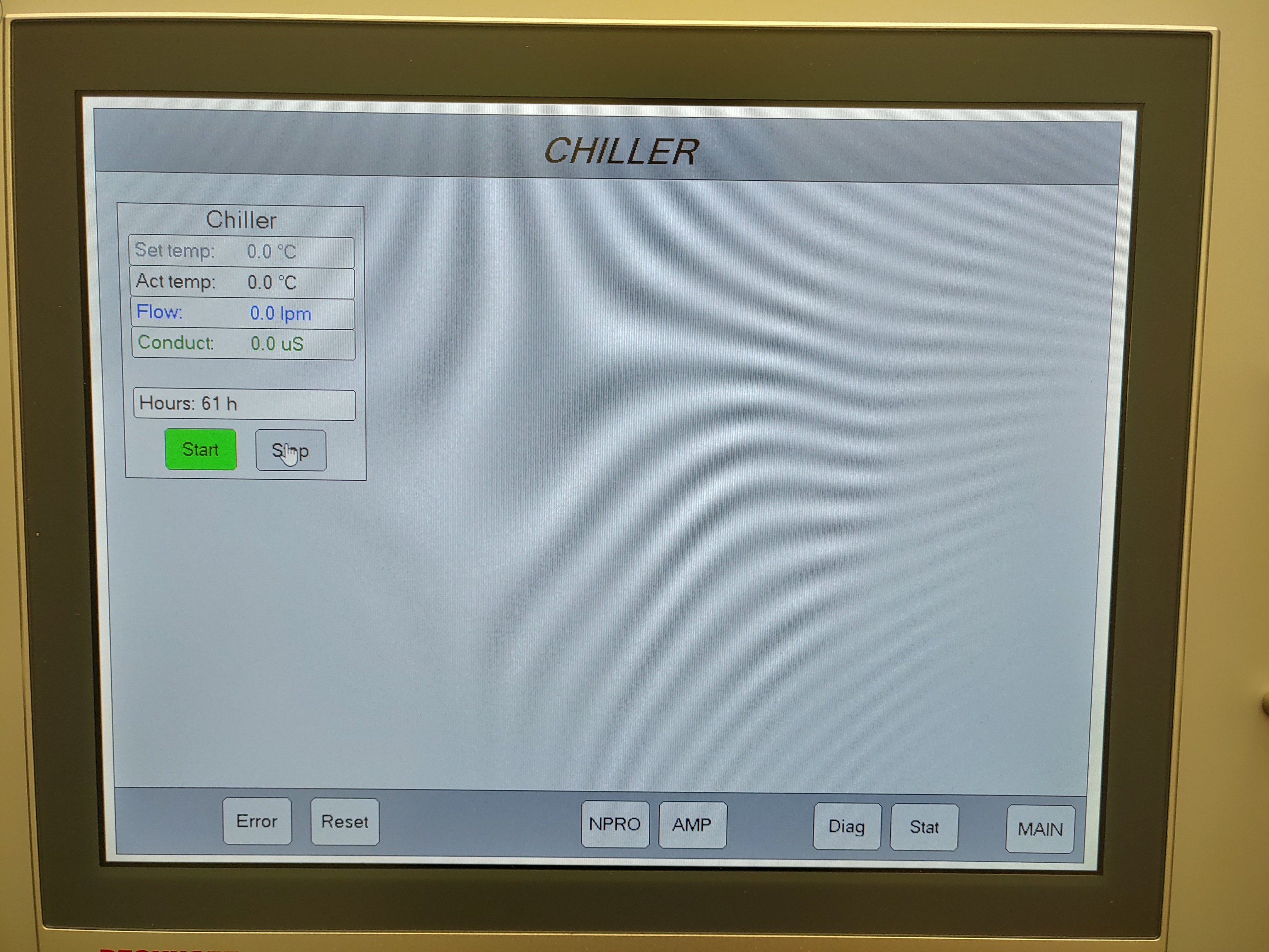
At this point we were ready to do some tests on the cooling system (remote chiller control/communication, flow/temp sensor functionality), so the control box wiring was completed and the chiller was wired to the new Beckhoff system. Once the control boxes were powered we confirmed that the Beckhoff PC and both control boxes were communicating and that the flow sensors were at least being read in. They were, but the the info being displayed was garbage (our cooling water is not 150+ °C and we're not flowing 50 lpm out of a chiller capable of ~9 lpm MAX flow). We grounded the flow sensor connectors, but this provided no change in the Beckhoff reading. The chiller was placed into remote turn-on mode and we were able to turn it on from Beckhoff (*fist pump*), but Beckhoff was not reading any info out of the chiller (like flow rate, water temp, conductivity, etc.); need to check if there's a setting in the chiller that needs to be set to allow sending of data to a remote connection. The chiller itself was reporting ~4.8 lpm of flow, and the displays on the new flow sensors (the new ones have external displays in addition to outputting the data) read ~4 lpm for the shorted loop (flow meter #2), ~0.8 lpm for the amp/DB loop (flow meter #1), and ~4.8 lpm for the overall flow (flow meter #3, outside the enclosure). These all add up, so it looks like the garbage reading in Beckhoff is a calibration issue. There is a table of settings in the software for setting these calibrations (flow/temp, V-to-W for PDs), so we will have to calibrate these readouts in Beckhoff so we're getting good info. No leaks were found in the amp/DB loop, so the chiller was shut off.
Next up is to complete the on-table wiring and cable routing in the PSL enclosure, which we will start on Tuesday after the Labor Day holiday. Also, we have been working with Fil for terminating the long-haul DC power cables for powering the pump diodes, at this point set for early next week. I've attached a few pictures I managed to take (the red Error light in New_Chiller_Flow.jpg is a Low Water Level error, easily cleared by adding more water), and will take several more on Tuesday and add them as a comment to this alog.