Sep/22/2021: All three green beams were roughly set up.
There were some surprises (see below).
Tomorrow we'll see if they clear the viewport simulator ring, and if they do we'll move to the IR beams.
What was done:
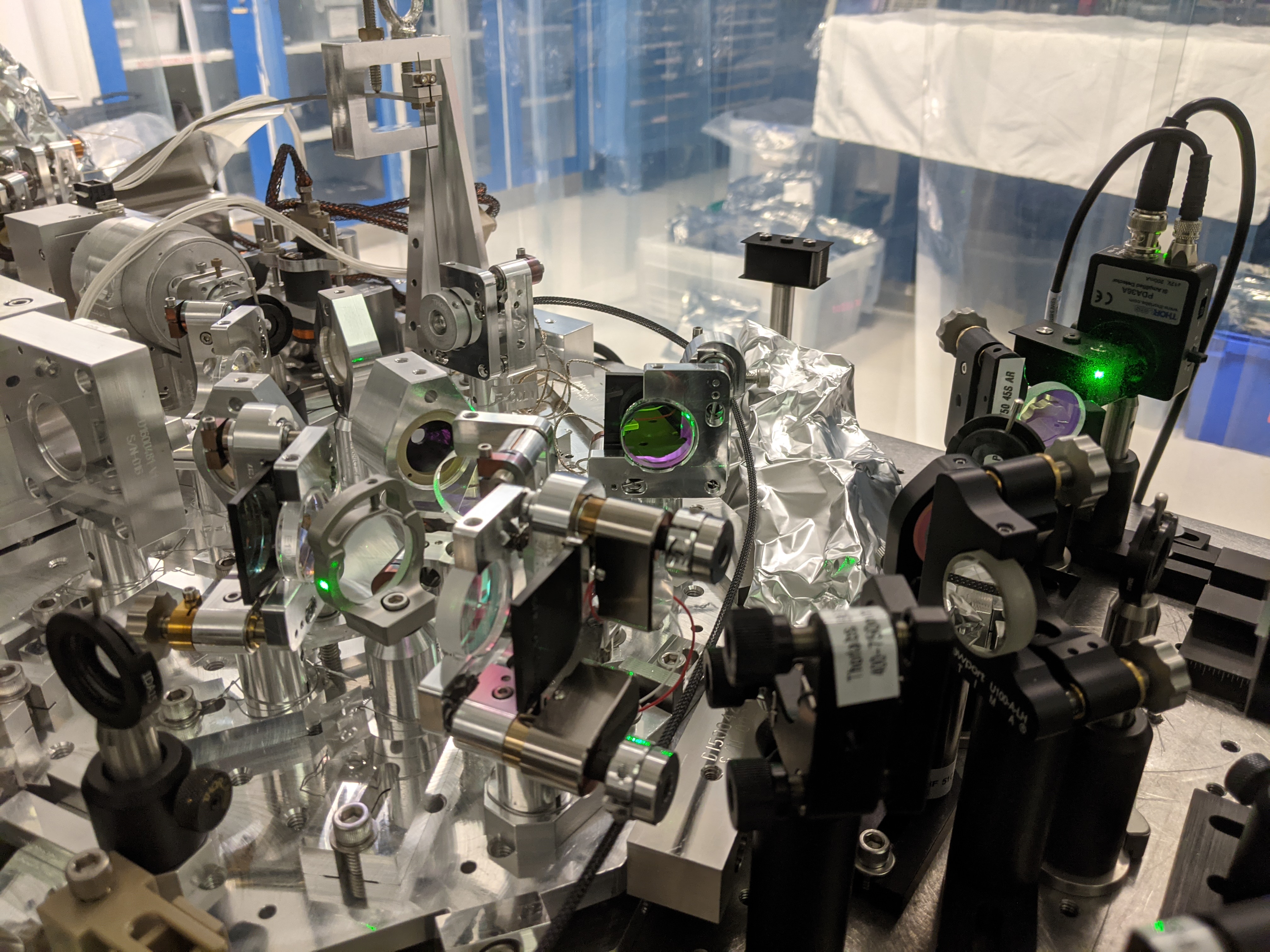
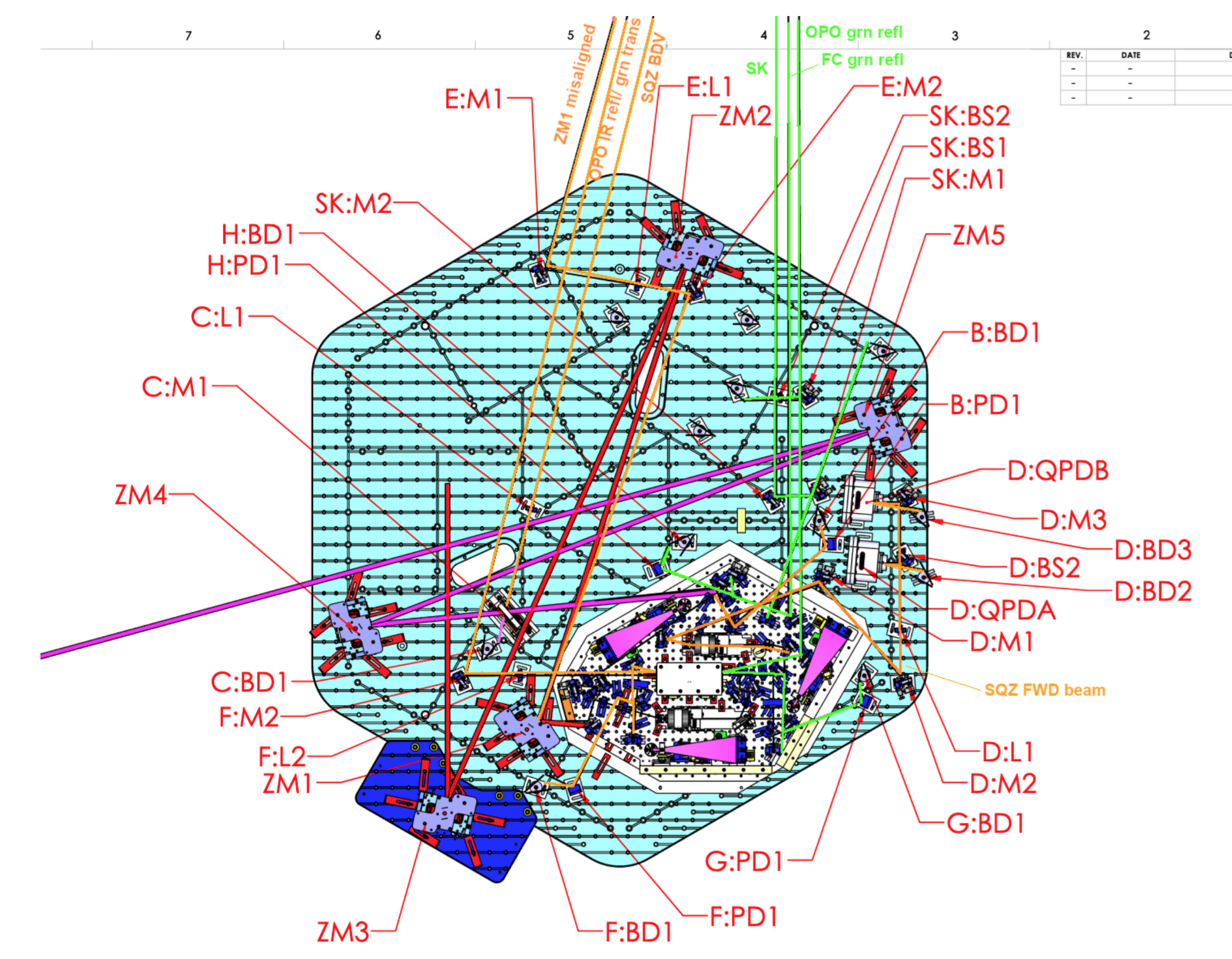
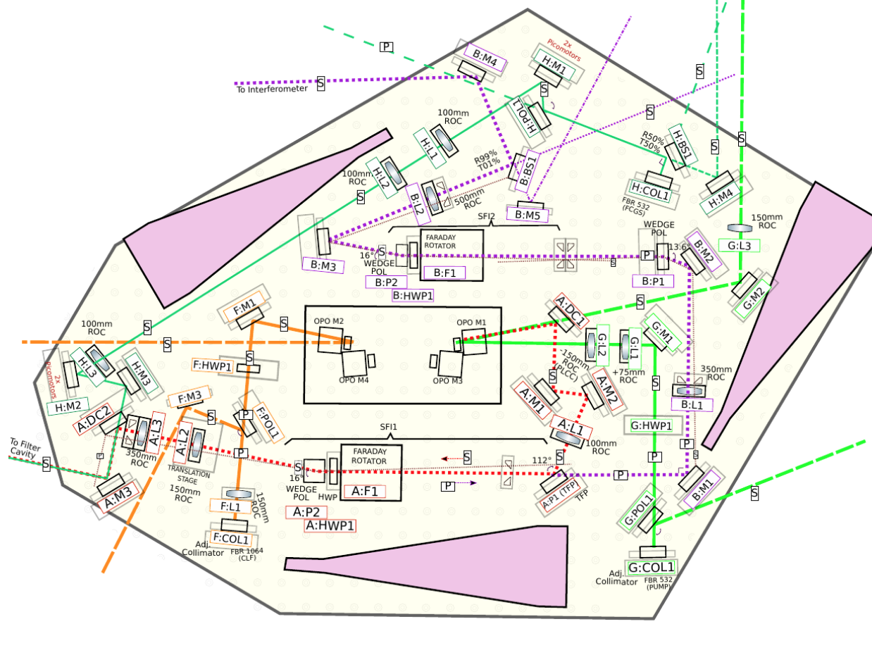
For component names, see the 1st and the 2nd attachment.
We connected a temporary PZT driver to the OPO PZT so we can scan it quicker. That way, it was easier to see the OPO IR transmission.
Temporary retro reflector at the ZM1 position was aligned so the beam retro reflected back through SFI1, then through SFI2 and to the IFO path.
Green beam from H path was coaligned with IR in FC path in the lab, but it was terribly off (see below). We recovered by moving H:M1 and H:M2.
We proceeded to set up the FC green retro-reflection path, OPO green REFL path and SK path (beat note of OPO REFL and straight-shot H path beam). We had to move the mirrors/BS towards the +Y door (see below, also Sheila will post pictures).
Surprise 1: H path alignment was terribly off. Probably it was H:M1 that was bumped or moved.
When IR was retro reflecting, green beam in H path (which is supposed to be coaligned with the IR in the FC path) was not retro reflecting at all. The beam was so much off in YAW at around H:M2, and the IR and green were crossing at an angle in the FC path.
My first guess was that the green fiber connector on the collimator was not well seated (or at least different from what it used to be in the optics lab) but it was a bad guess. Reseating the fiber on the collimator didn't do anything though, and our attempt to moved the collimator in YAW as well as H:M2 for coalignment was unsuccessful (turns out that the collimator is a poor actuator to change beam position on H:M2).
We looked at the focal length of the lenses and distances between the components along the beam path and figured out that it's much more likely that H:M1 moved, and maybe H:M2 too, but not the collimator.
We undid most of what we did to the collimator though we didn't do so completely, then moved H:M1 until one of the ghost beams fell on a known spot using the picutre shot in June as a reference. We removed the retro mirror from FC path and moved H:M2, checking IR-green coalignment. We thought that we might also have to use H:M3 to get green coaligned, but H:M2 was all we needed.
Problem solved.
We don't know why H:M1 moved, it could be that it was bumped because it's sticking out of the OPO platform footprint (it has pico), or that we had to remove the J-clamp for the black glass and reattach, which requires some force.
Surprise 2: H path collimator beam was not angled as specified in the diagram.
If you look at the 2nd attachment, H path collimator beam is half-reflected and half-transmitted by H:BS1. Let's call the H:BS1 transmission the H path straight-shot beam. If you look at the first attachment, this H path straight shot beam meets with the FC path retro-reflection as well as OPO green reflection at 15 degrees or so (my eyeballing). In reality this angle was much shallower even in the lab.
Because of this, H path straight shot beam crosses with the OPO green reflection at the place much closer to +Y door than in the drawing. This should be OK, we pushed all relevant BSs and mirrors in +Y direction. Nothing interferes with ZM6-ZM5-ZM4 beam lines. Sheila will post pictures.
Thu. Sep/23/2021: Three green beams (SK, green OPO refl, green FC refl) and two IR beams (CLF refl and FC BDV) are done for now.
Viewport simulator was put in place on the +Y door of HAM7.
Green paths:
Three green beams are already going in the right direction, but they were much lower than the center line of the hoop. These beams were about level with ISI table surface and about the right height relative to ISI. We had to point the beams up.
Side effect of that was that we had to raise SK:M2 by 3/8" (doubling up the ISC base plate) while SK:BS1 and SK:BS2 were raised by 3/4" (tripling the base plate). I also changed the SK path a bit so that the lever arm for SK:M1 pico mirror will be much larger than SK:BS2. Sheila and/or Camilla will post pictures.
It turns out that there's no detailed diagram for how the SK beam will be handled by the periscope. We aligned the SK beam such that it will be close to the FC refl beam at the periscope location so that they could be picked up by one 2" mirror.
We haven't placed beam dumps.
IR paths:
CLF REFL beam was aligned to clear the viewport simulator. This is bright and easy.
For BDV REFL beam, first of all the steering mirror for IFO path on OPO platform (B:M4) was adjusted to steer the IR beam to where ZM4 would be (it was already pretty good w/o adjustment but we did it anyway). The beam diverter location/angle was adjusted such that
- the IFO path beam reflected by the beam diverter clears the viewport simulator when the beam diverter is closed,
- the beam diverter itself won't interfere with the CLF REFL beam.
Note that the BDV path needs to be redone when ZM4-ZM5 are installed. In addition, the beam coming to BDV is hard to see for now because the power is not that much and we're just seeing the flash of the OPO while scanning it, it would be easier when SQZT7 will be in place. Because of these, we did not bother to put the lens (C:L1) in the BDV path.
We did NOT do the following.
- ZM1-misaligned path because we don't have ZM1.
- QPD path. We cannot see the beam. This will be set up after SQZT7 is moved in place (to lock OPO) and when +X door is removed.
- For the same reason as the QPD path, we didn't even try to set up a retro reflector in the IFO path to set up the monitor PD for the reflection from IFO. Again, this will be set up after we can lock the OPO and when +X door is removed.
- Wrong polarization for Pump and IR. Easy access from -Y side but we need PDs.
- Wrong polarization for green FC sensing light. We need PDs.
- Beam dumps (IR, green).
For now we're done with HAM7 ISC alignment that could be done at this point. If people need laser safe the first thing on Friday, feel free to transition. Viewport simulator is still on HAM7, but you can remove it if you want. It's easy to put it back on if necessary.
Camilla, Keita, Sheila (Follow up on Keita's entry above.)
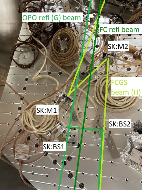
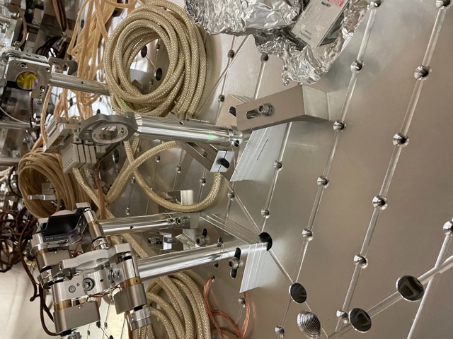
The first photo here shows' how the SK path is moved in the +Y direction relative to the layout, which we did because the angle of the H path collimator was not as the drawing indicated. In the photo, I annotated the H beam (filter cavity green sensing) in yellow green, this is the beam which should have been more angled to match the HAM7 layout. It crosses the OPO refl (G) beam closer to the +Y side of HAM7 than the layout expects, so we had to move SK:M1 in the +Y direction compared to the layout. If we had used this mirror at 45 degrees AOI, we would have had a very short lever arm for the two picos (SK:M1 and SK:BS1) which are intended to optimize the interference on SK:BS2. To give us a little bit more of a lever arm, we placed SK:M1 at a smaller angle of incidence and quickly checked that the reflectivity was not changed with a power meter. Keita measured the distances between all of these paths. We showed this change to Rahul who thinks that this will not be a problem for the ZM5 installation. (ZM5 cookie cutter is visible in upper left of the first photo).
The second photo shows how we stacked bases. As Keita said, once the viewport simulator was installed we could see that we needed to angle the beams up from the VIP to reach the center of the viewports, I'm tagging systems since we have a question about this. The posts for the SK path are set as though the beam should be parallel to the table. If we had not had moved these optics in the +Y direction, this might have worked OK as the optics would be closer to the VIP where the beam is lower. As it was, we stacked base plates below the optics, 3 bases total below SK:BS1, and 2 bases total below SK:BS2 (the normal 1 base below SK:M1 and SK:M2). The question this raises is were these beams expected to angle up to go out the viewport, or do we need to be concerned that there is something wrong with the viewport simulator (or something unexpected about the HAM7 door)?
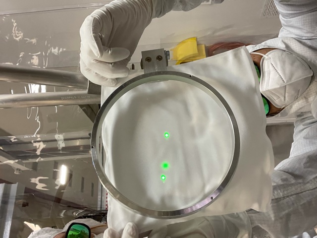
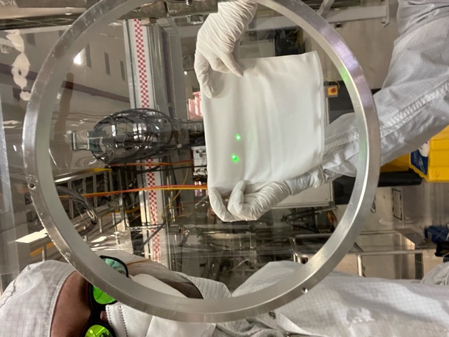
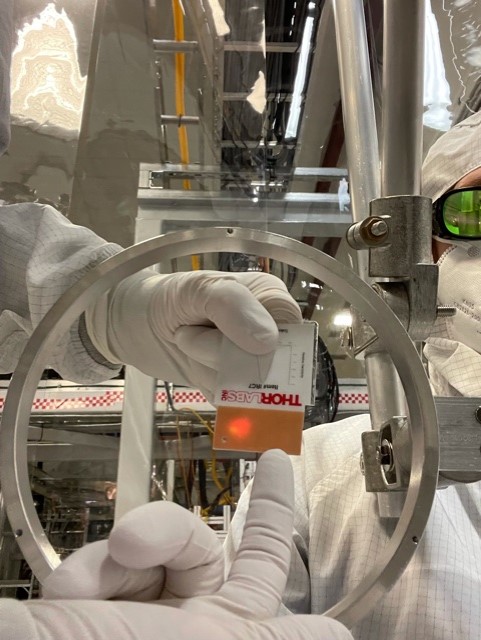
The next few photos show the locations of beams towards SQZT7. THe first shows the three green beams at the viewport location, from left to right they are SK path, filter cavity reflection, and OPO reflection (G). The next shows keita holding the wipe at approximately the location of the periscope top, where the SK beam and FC refl beam will hit the same mirror, and the OPO refl beam will be on the other mirror. The beams aren't quite parallel as you can see, but they are centered reasonably well on the viewport. (Apologies for my hair flying out of the hood here). The last photo shows the two IR beams that we aligned on the viewport, the CLF (seed) reflected off the OPO M2 is the bright beam, and the beam heading towards the IFO is reflected off the beam diverter. This low power beam was difficult to see with the OPO flashing; Camilla is pointing to the location on the card, where it is slightly lower than the CLF reflected beam.
Reconciling the beam height thing (Camilla, Sheila, Betsy, Keita)
We did a bit of detective work and believe that things make sense.
First, using D1900267-v8, the height of the viewports for FC1 as well as SQZT7 measured from the floor at LHO are supposed to be 74.4-3.94=70.46".
2nd, only at LHO, the center of FC1 and ZM3 are supposed to be ~3/4" (0.756" to be exact) higher than everything else. See page 6 of G1901764-v6, also there's a spacer document T2000104 that supports this. If the beam coming out of VOPO is level with ISI surface, it's nominally 5.532" high, but we need to point the beam up from ZM2 toward ZM3 to raise the beam height by 0.756".
3rd, using D1900267-v8 and D1900264, we know that the height of the ISI surface from the floor is supposed to be 74.4-10.14=64.26". Betsy measured this using tape measure and it was 64".
Below is a table summarizing how things are supposed to be:
| Nominal height | If we use Betsy's number | |
| Floor to FC1 and SQZT7 viewport | 70.46" | |
| VOPO and ZM1/2/4/5 relative to ISI surface | 5.532" | |
| FC1 and ZM3 height relative to ISI surface | 6.288" | |
| Floor to ISI surface | 64.26 | 64" |
| Floor to VOPO and ZM1/2/4/5 |
5.532+64.26=69.792" (0.668" or 17mm lower than the VP center) |
5.532+64=69.532" (0.928" or 23.6mm lower than the VP center) |
| Floor to FC1 and ZM3 |
6.288+64.26=70.548" (0.088" or 2.2mm higher than the VP center) |
6.288+64=70.288 (0.172" or 4.4mm lower than the VP center) |
We had to raise the green beams by ~1" at the VP simulator position to center them on the VP simulator hoop. If we take the nominal "floor to ISI surface" number, this adjustment of ~1" is only ~0.33" or 8mm larger than expected. If we take Betsy's number, it's only ~2mm larger than expected.
Either way, a large part of this mystery (for LHO people) was due to the LHO-specific requirement that FC1 beam needs to be ~3/4" higher than VOPO and ZM1/2/4/5 and that FC1 beam needs to be about centered in the FC tube.
BTW, 3/4" over ~1m lever arm is ~20mrad, we have to tilt ZM2 up and ZM3 down by half of that so the FC beam comes to the right height and angle. Though the impact on the modematching due to larger AOI should be minimal (e.g. cos(10mrad)~0.99995), can we tilt ZM2/ZM3 this much without rebalancing mechanically?
| Nominal height | Nominal height | If we use Betsy's number | From SYS (Eddie) extracted from LHO CAD and Optical Layout | From Lee M (extracted from e-mail) |
| Floor to FC1 and SQZT7 viewport | 70.46" | 70.499" | ||
| FC1 to center of A2F5 | 70.514" (no pitch on nozzle) | |||
| VOPO and ZM1/2/4/5 relative to ISI surface | 5.532" | 5.532" | ||
| FC1 and ZM3 height relative to ISI surface | 6.288" | 6.268" | ||
| Floor to ISI surface | 64.26 | 64" | 64.231" | |
| Floor to A2F4 and A2F3 | 70.873 (nozzle's pitched 5 degree) | |||
| In air ISC table to in VAC ISC table components | 1" difference (matches your findings) | |||
| Floor to VOPO and ZM1/2/4/5 |
5.532+64.26=69.792" (0.668" or 17mm lower than the VP center) |
5.532+64=69.532" (0.928" or 23.6mm lower than the VP center) |
The spacers for FC1, ZM3 and ZM2 are custom for this height change. We actually are going to begin pitching the beam at ZM1 and then unpitch it at ZM3. This is because the ZM1 and ZM3 are both flat and not the HPDS/PSAMS. They are the simpler HDDS. That will be 131" path for the .75" height change, which is only 2.8mRad of pitch on ZM1 and ZM3. ZM2 is then without pitch and held at the intermediate height as the beam is raising between ZM1 and ZM3. | |
| Floor to FC1 and ZM3 |
6.288+64.26=70.548" (0.088" or 2.2mm higher than the VP center) |
6.288+64=70.288 (0.172" or 4.4mm lower than the VP center) |
|
The pitch of ZM3 is known for this height offset and systems has checked in with me about it. |