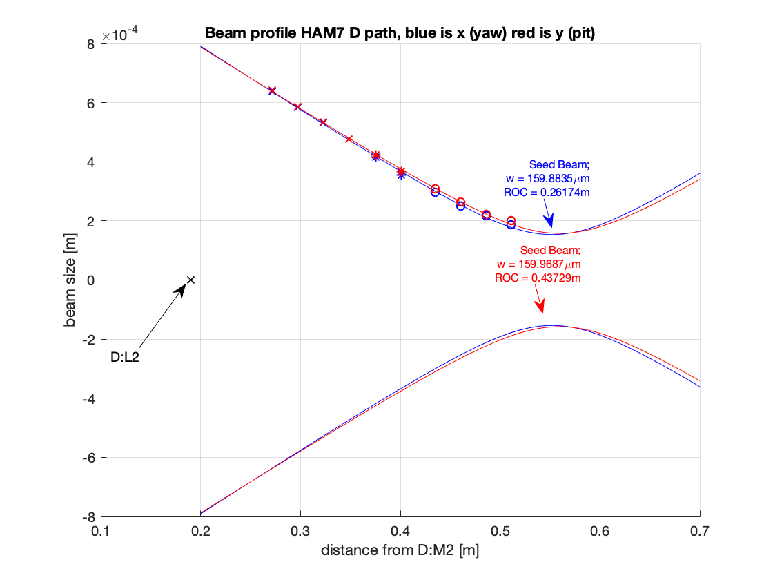
On Friday, after aligning B:PD1 and installing D:L1 (see layout diagrams here and here), Sheila and Camilla took a beam profile of the D:path, where the squeezer QPDs will eventually be placed.
The a la mode script and plot are attached. The different marker types on the plot indicate separate meaurements where the beam profiler rail position was moved.
We found there was a 160um waist 553.5mm from D:M2. According page 32 to the FC layout design we should have a 90um waist 587mm from D:M2. The waist is 1.7 times larger than design, which will increase the Rayleigh range by a factor of ~3, and change where the wavefront sensors need to be placed. Maybe we could use a shorter focal length lens placed closer to the WFS to get the design waist?

Some quick distance measurements:
bs1 to upstream lens: 115mm
bs1 to D:M1 335mm
D:M1 to D:M2 390mm
D:M2 to D:L1 185mm
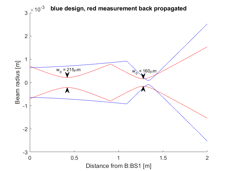
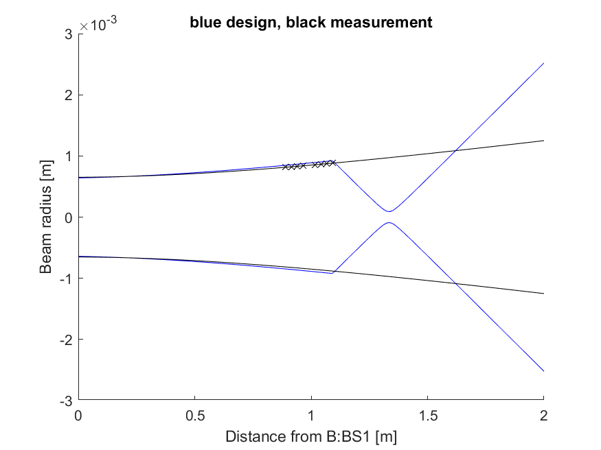
I used Georgia's waist value above and the distance measurements to compare the beam that we measured to the expectation from Fig 19 in T1900649 The attached plot shows the measured beam back propagated through the measured lens location, compared to the design.
We placed the lens by according to the HAM7 drawing, not according to the distances in T1900649, as you can see in the figure the design calls for the lens to be further along the beam path which would result in a smaller waist. It does seem from this that the beam leaving the platform is fairly different from the design though. The mode matching checks for the B path (FC to IFO) are documented in 59333 and seemed quite good. When we are next laser hazard we can measure the beam at this location without any lens installed to see if our beam is really this different from the design.
In laser hazard this afternoon Camilla and I removed the lens and re-measured the beam profile for the D (QPD) path. The png attachment shows that what we measured is in good agreement with the design beam parameter coming from the VIP (98% horizontal overlap, 99.7% vertical overlap). We looked at where we would need to place the lens D:L1 and D:M3 with the current positions of D:M1 and D:M2, and we don't have enough space. We think that we can move D:M1 a few inches and possibly move D:M2's base a little so it hangs off the ISI and fit everything with distances and waists similar to the design.
Also this afternoon Camilla checked on the alignment of the retro reflector in the SQZ to IFO path, which seems pretty good (the beam arrives at SFI2 roughly centered on the apperture). The retroreflected beam for B:PD1 (OFI rejected beam monitor) was still high, so Camilla added a second for to get the height correct. She aligned this approximately but it was difficult to see and we will check with the IR camera in the morning.
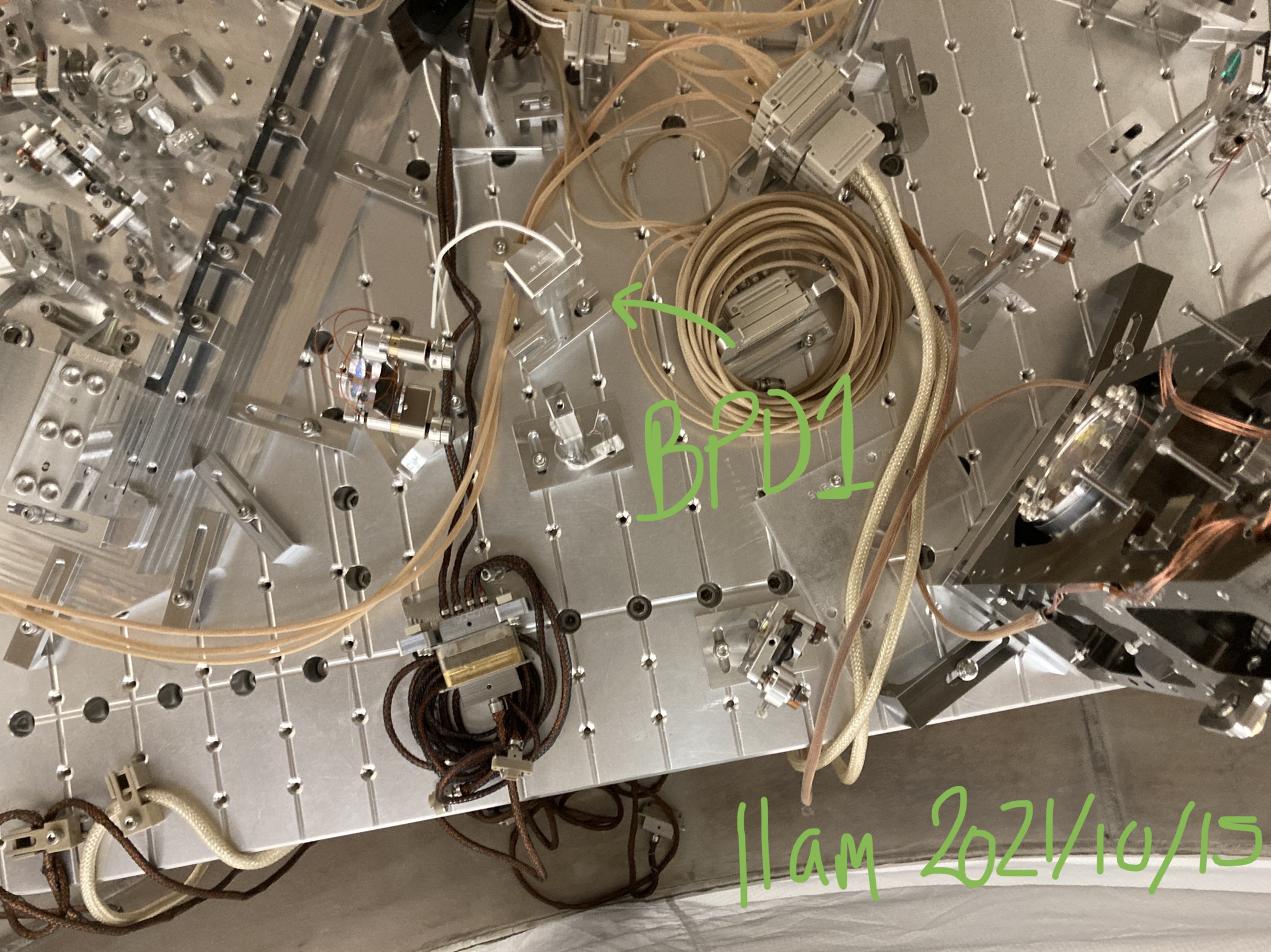
We aren't sure what was meant by "Camilla added a second for to get the height correct" in alog 60276 above, but from the attached photo taken a day later you can see a spacer was not added to B:PD1. I do not have an IR photo of the beam on this PD (I have photos of F:PD1 that morning 64560 but not B:PD1).
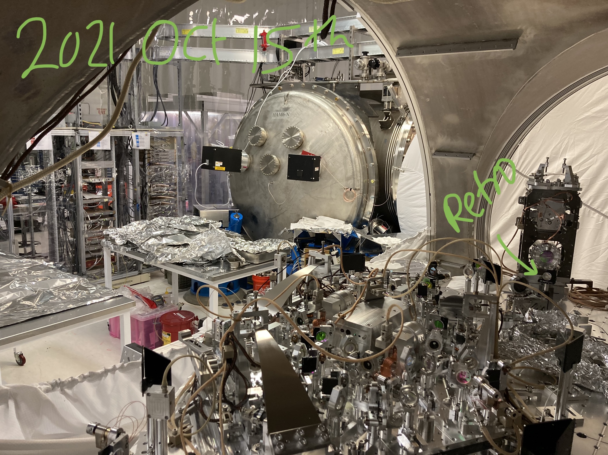
The position of the retro-reflector was in between the Beam diverter and ZM4, as seen in the attached photo.