This morning we returned to the HAM5/7 alignment.
We did not rely on the HAM5 aux laser for the alignment today. This laser was once aligned to reflect off the center of SRM and retro reflect back towards the laser, and also to be centered on SR2. This was done with SRM in an alignment very different from the alignment used for SRM while running, which was OK for the purposes of OFI alignment. (The beam is centered on SR2 and SRM, and the retro reflection ensures that the beam transmitted through SRM is along that beamline). Yesterday we saw that the beam was no longer retro reflecting for this SRM alignment, probably because something has moved durring the last month of work in HAM5. For our beam which is reflected off SRM, Betsy restored SRM to the alignment used while observing (60342). Camilla went to SR2 to check the beam position there, and Lee watched the beam position at the iris right in front of SRM and Wen adjusted ZM5 sliders to align on the iris, and used the pico on the OFI to adjust the position on the SR2 scrapper baffle. We used the pico because we were going to quickly use up the range on ZM6 sliders. After this the beam was transmitted towards HAM6, slightly to the +X side on the septum which is similar to what Betsy said they saw while aligning the OFI.
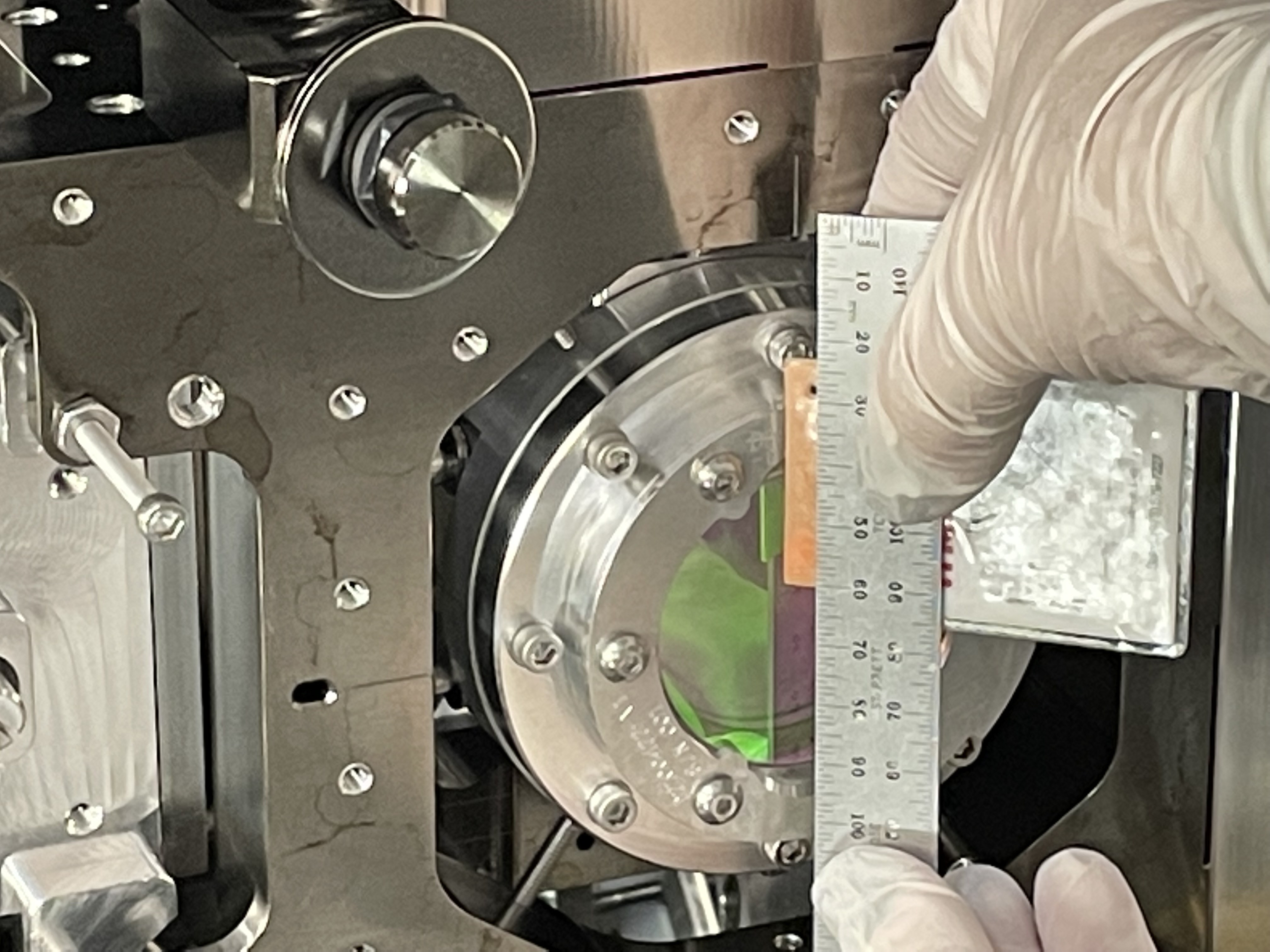
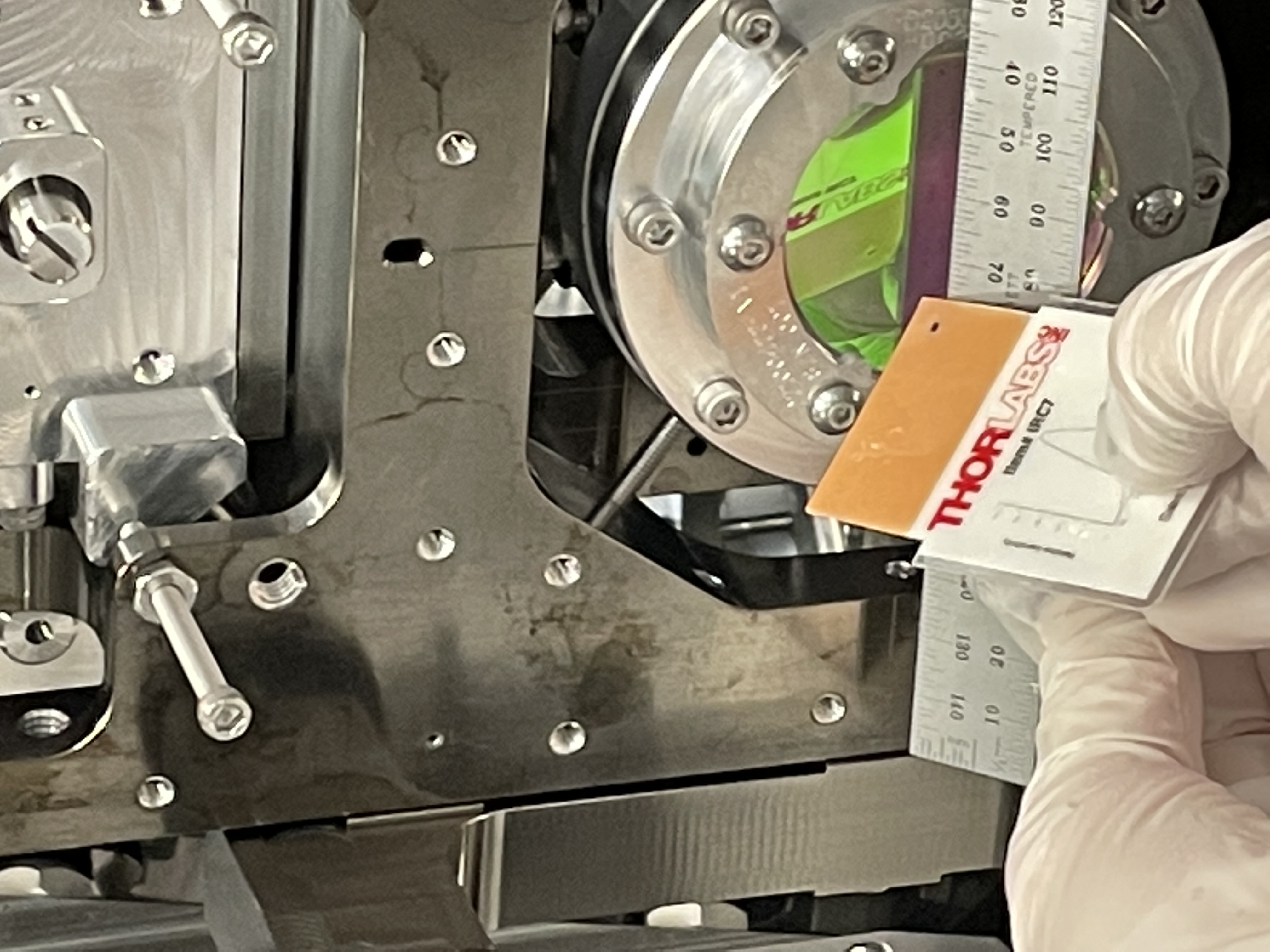
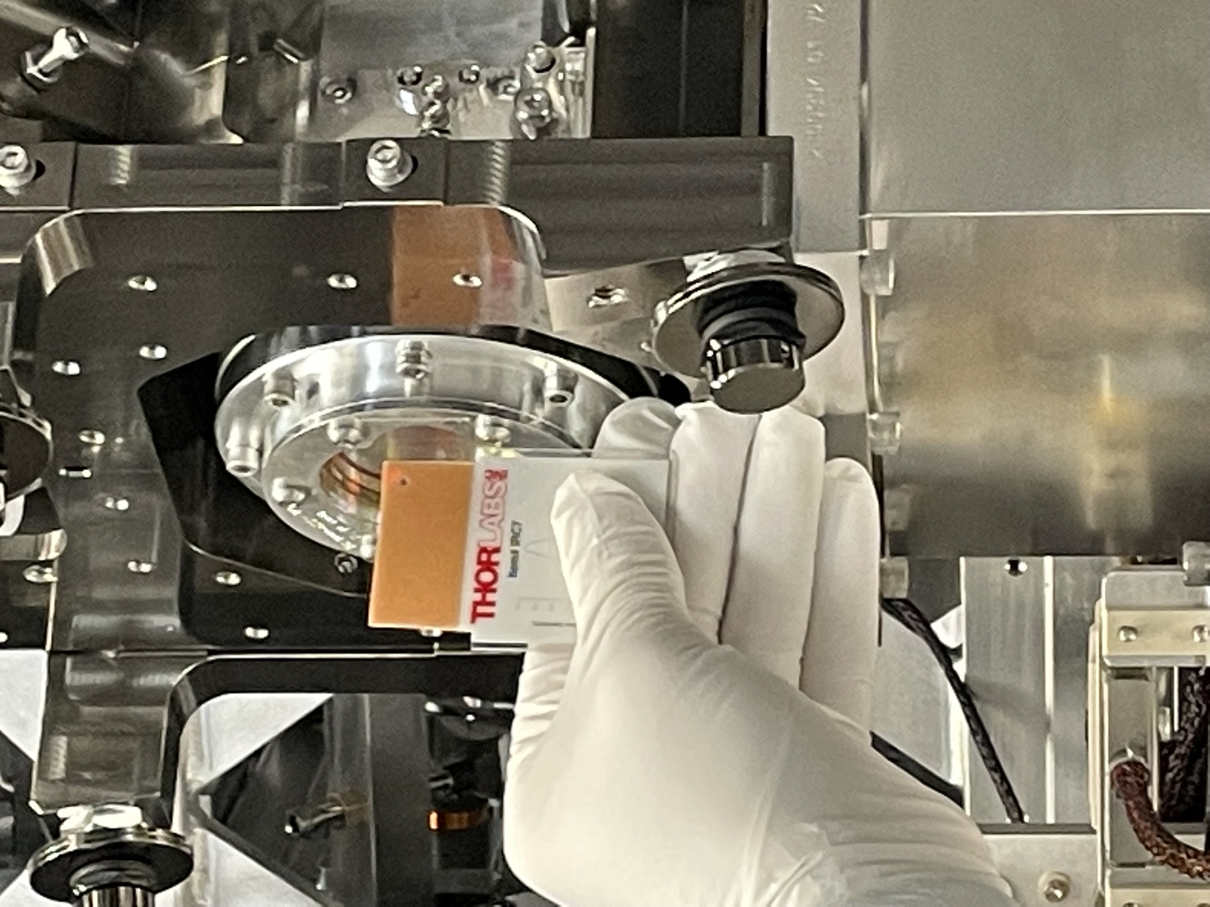
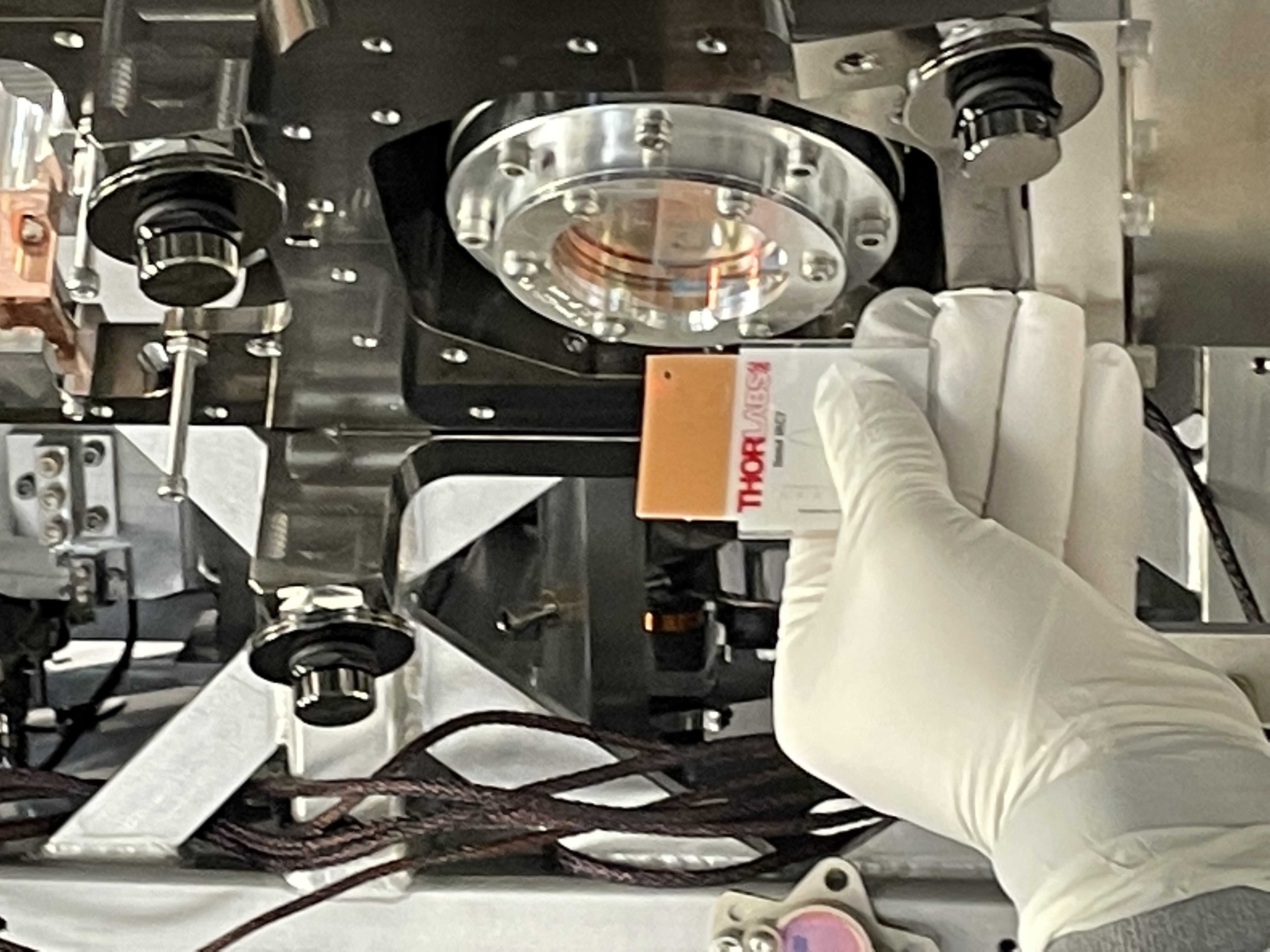
Because we moved ZM5, we checked the centering on ZM6 after this was done. In the first two photos Betsy is holding a ruler so that 40mm and 100mm marks are on the edge of the ZM6 holder, which means the center of the optic is at the 70mm mark. In the first photo the beam is barely visible, but it is centered around the 55mm mark, so 15mm from the center, while the second photo shows the reflected beam is at 75mm. So the beam is about 5mm closer to the -X side of ZM6. This will be a smaller shift in the position of the beam in the tube to HAM7 (because of the large angle of ZM6). We decided to leave this miscentering for now, the baffle which will set this aperture will be ready in a couple of days so we can see then if there is enough slop in the way the baffle is mounted to accommodate this. The next two attached photos are Lee's method of checking centering, he can comment on what these photos mean :)
There are three beams reflecting off the OFI pico mirror, one ghost beam dumped on the ZM6 baffle and the rejected polarization monitor. Since we moved the pico we turned on the HAM5 aux laser, which isn't a great alignment reference anymore. We saw that the beam was still hitting the PD, and centered on the lens in that path. We adjusted the steering mirror in front of the PD to maximize the signal, but that adjustment was very small.
We believe that it is now OK to remove the aux laser from HAM5. The only thing that we used that laser for today was to see a beam from the rejected polarization. If we do find that we need to center the beam on ZM6 better, we can use our beam from the squeezer and look at it's position on SR2 again. If we need to double check the rejected polarization PD, we can use a temporary half wave plate before the OFI to see our beam heading towards that PD. This means that we should be OK with pulling the temporary laser set up off HAM5, if the OFI rejected polarization PD has been calibrated.
Before leaving for lunch, Camilla Wen and I did a quick check of the F:PD1 calibration (CLF fiber rejected polarization monitor). We adjusted the seed path quarter and half wave plates and reduced the seed power to avoid saturating on the 30dB gain setting. We measured 8.525V with 1.69mW, giving a responsivity of 0.08A/W which is not much bigger than what we measured for B:PD1 60284
Further F:PD1 check: Transimpedance amplifier/whitening is OK.
I did some basic checks on the floor for F:PD1 and everything made sense. Responsivity of these DC diodes are really 0.06~0.08A/W unless both F:PD1 and B:PD1 are broken.
1. Checked that the photocurrent on the MEDM (H1:SQZ-CLF_FIBR_REJECTED_DC_DCCURRENT) was ~0.14, presumably mA.
2. Measured the current by a multimeter and it was indeed 0.14mA.
To do this, I used two breakout boards to insert the meter between the DCPD and the PD interface at the front panel of the SQZ Vac. Interface Chassis (SQZ-R2 U8, D2100369).
3. Confirmed that the voltage on MEDM (H1:SQZ-CLF_FIBR_REJECTED_DC_VOLTS) was proportional to the whitening gain (0 to 30dB).
4. Disconncted the photodiode from the front panel of the SQZ Vac. Interface, used a breakout board to short the input for cathode and anode on the chassis, and confirmed that the cathode-in voltage was -5V. This is consistent with the PD interface circuit (D1200543).
5. Just because I could, I also connected 1k resistor between cathode and anode inputs. Cathode-in voltage dropped to -2.5V, just as expected because of 1k input resistance. With the whitening gain set to 0dB, H1:SQZ-CLF_FIBR_REJECTED_DC_VOLTS was 5V (current is 5V/(1k+1k)=2.5mA, 1k feedback resistor in the first stage, x2 gain in the last stage). Again everything is as expected.