This morning Sheila and I re-measured the beam size on reflection of ZM6. This was previously done (alog 60411) however the beam was not centered on ZM5 for these measurements (alog 60425) so we wanted to retake some data.
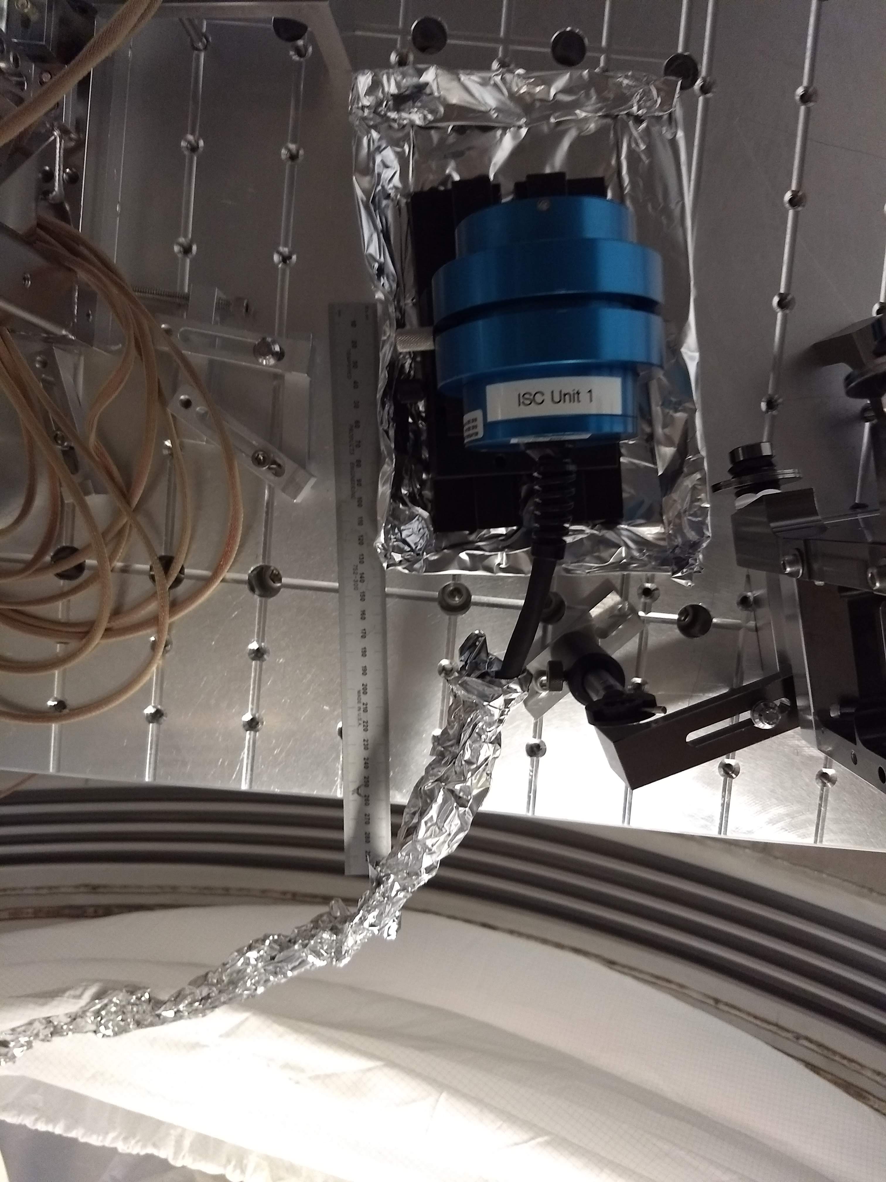
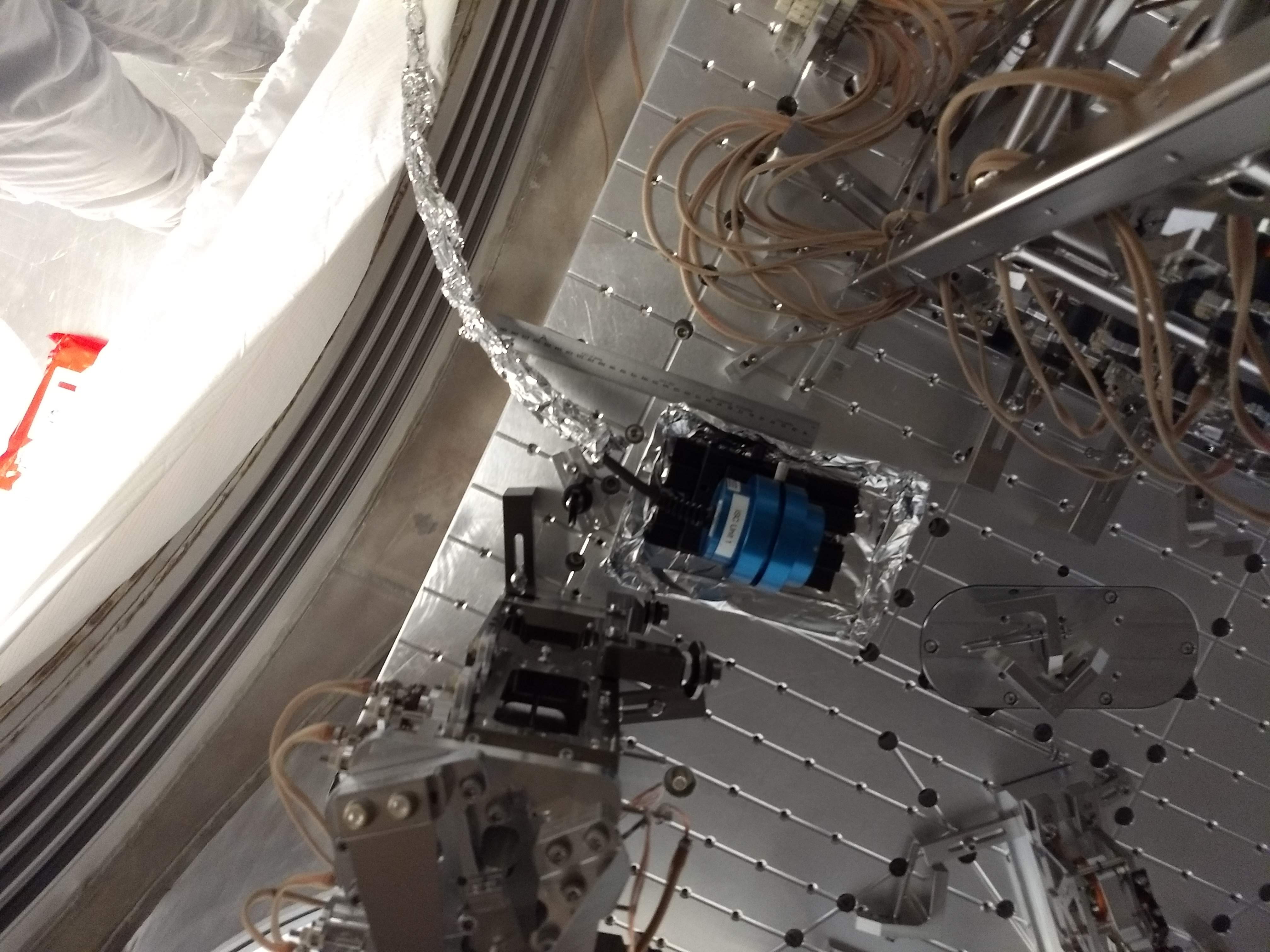
We put the nanoscan on the beam reflected off ZM5 and heading towards HAM5. The profilers was ~26cm from the edge of the ISI (measured roughly along the beam path). The profiler position is shown in the two attached photos.
We first swept the PZT voltage on ZM5 from 0 to 120V, keeping the ZM4 voltage at 0V. Then we stepped the ZM4 PZT up to 100V and swept the ZM5 PZT volage back down. I'm attaching the the PZT voltage, 13.5% beam diameter data, and strain gauge voltage below.
Other quick notes from HAM7 yesterday.
ZM5 alignment restored. When Jeff calibrated the alignment sliders, 60632, he didn't update alignment offsets so the alingment of ZM5 was wrong. When Camilla logged the slider values 60446 the gain of the pitch slider was 1, but the yaw slider had a gain of 4. Now I've adjusted the offsets so that the outputs are the same as when we did the alignment and set irses. ZM4+ ZM6 had 0 offset, so no changes were needed. For ZM5 the new offsets are 201 for pit, 3196 for yaw to reproduce the outputs from before the calibration.
CLF lens swapped. Another quick thing that we did yesterday was swap the lens in the CLF refl (F) path to give us a better collimated beam heading towards SQZT7. There was a lens installed in this path labeld F:L1, looking at the scribe on the barrel with a flashlight it was E2000077 05, (+150mm ROC). We instead used the lens that was mounted in a post labeled C:L1, which is E2000077-07 (+250mm ROC). This resulted in a smaller beam on SQZT7 periscope, and we realigned to get the green transmission onto the PDA100A.
Betsy also came and had a look at how we could place ZM1; we have a few things in the way. The CLF refl lens was one thing that was possibly in the way, but after we swapped it Georgia placed it after the steering mirror so that it will no longer be close to ZM1. The retro-reflection mirror used to imitate ZM1 for the alignment of the ZM4,5,6 to HAM5 path is going to have to move before we can place ZM1.
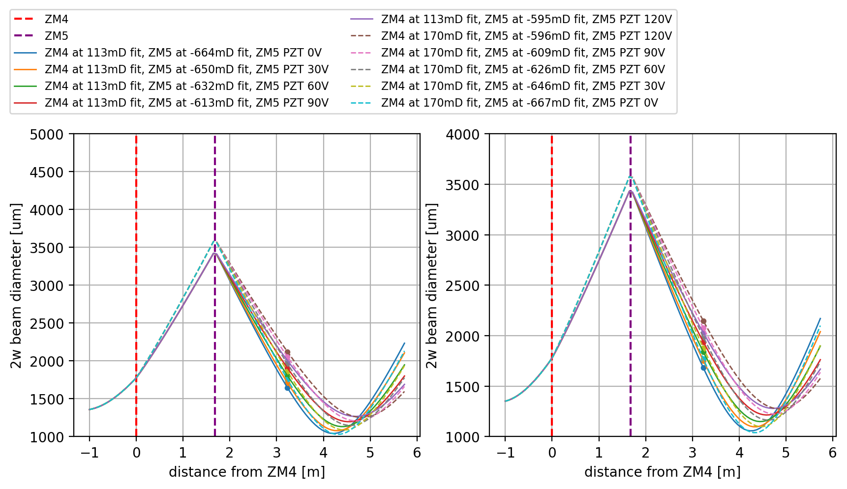
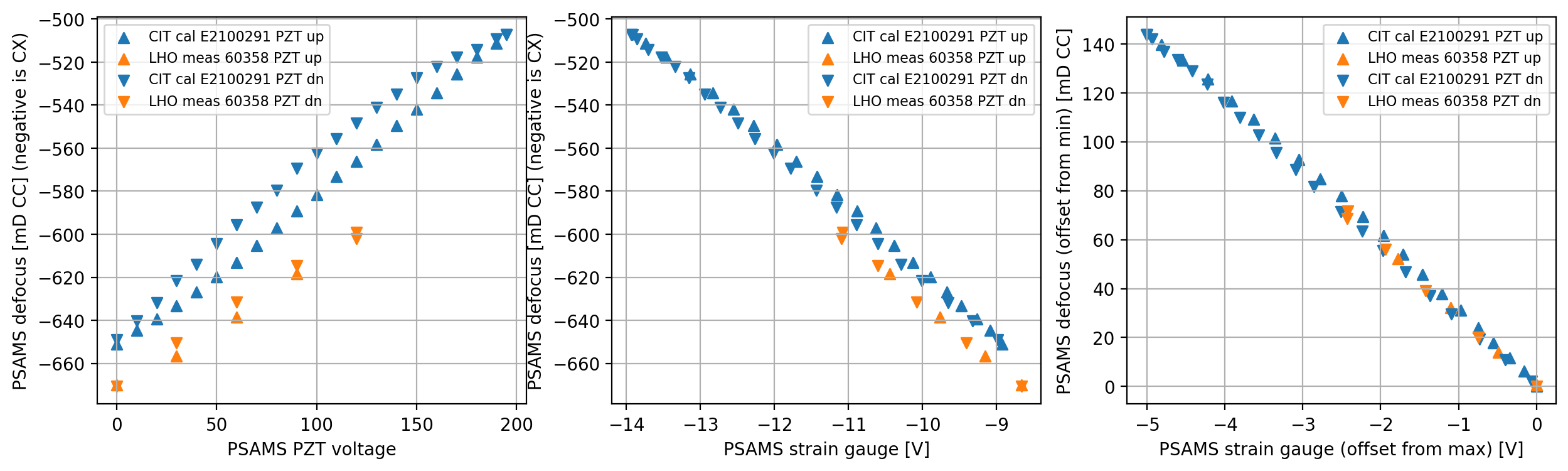
Here are the analogous plots and tables as LHO60411 for this new data. Here I'm just including the new ZM5 data. I'm getting about 10mD different at the new beam location than the previous dataset. This makes the data overlap a bit worse than the CIT calibrations, by about that same 10mD.
ZM4 PZT [V] ZM4 strain ZM4 defocus ZM4 defocus ZM5 PZT [V] ZM5 strain diam X [um] ZM5 defocus diam Y [um] ZM5 defocus ZM5 q_X ZM5 q_Y
gauge [V] X [mD] Y [mD] gauge [V] X [mD] Y [mD]
------------- ------------ ------------- ------------- ------------- ------------ ------------- ------------- ------------- ------------- ------------- -------------
0 10.81 113 109 0 -8.66 1646 -670.146 1682 -663.666 -2.542+0.797i -2.572+0.825i
0 10.81 113 109 30 -9.15 1713 -656.73 1753 -649.538 -2.622+0.854i -2.659+0.888i
0 10.81 113 109 60 -9.76 1805 -638.429 1840 -632.331 -2.739+0.942i -2.771+0.975i
0 10.81 113 109 90 -10.44 1906 -618.475 1939 -612.871 -2.876+1.054i -2.907+1.089i
0 10.81 113 109 120 -11.08 2005 -599.032 2029 -595.275 -3.021+1.181i -3.039+1.209i
100 8.74 170 162 120 -11.09 2122 -602.035 2148 -596.422 -3.152+1.158i -3.179+1.200i
100 8.74 170 162 90 -10.6 2054 -614.67 2078 -609.423 -3.046+1.071i -3.069+1.106i
100 8.74 170 162 60 -10.08 1963 -631.636 1988 -626.193 -2.913+0.968i -2.936+1.000i
100 8.74 170 162 30 -9.41 1862 -650.556 1880 -646.412 -2.776+0.869i -2.789+0.891i
100 8.74 170 162 0 -8.66 1755 -670.723 1771 -666.945 -2.642+0.779i -2.652+0.797i
I have the mirror phase map of ZM5-SN1 that is installed. Here is the mirror map processed to indicate the curvature applied to the beam at any beam spot along the surface: curvatureC.pdf There are some unusual features in this mirror map, and it is one of the earlier ones before the measurement process with the ZMs may have been perfected. In any case, you can see that there is some variation along the optic which could explain the 10mD difference in the previous dataset. It could also explain that the CIT calibration may be off by some amount, as it is not clear what point on the optic it is most representative of the overall curvature in the CIT measurement., presumably some sort of average over the surface


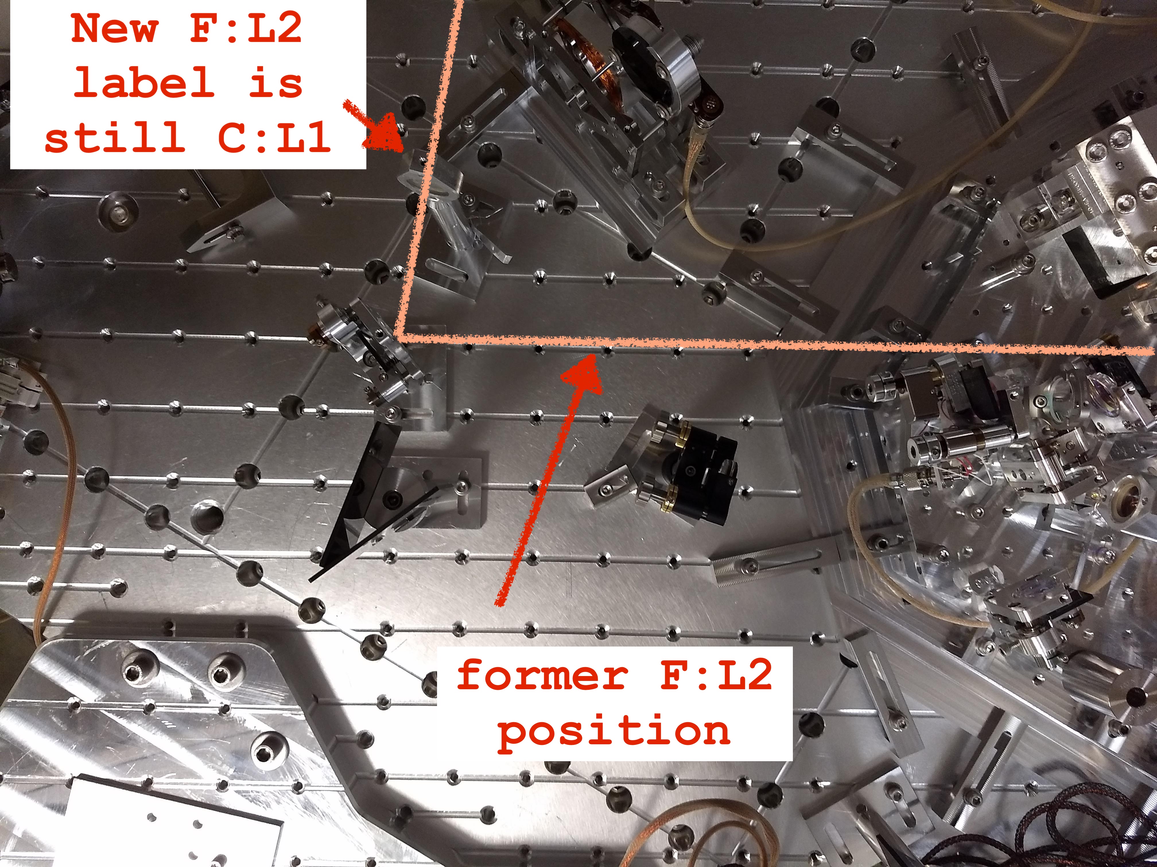
Following the thread of Sheila's comment - I'm attaching a pic of the new F:L2 (label attached to the mount is C:L1) in it's location between the VOPO and SQZT7.
We moved it to the other side of F:M2 so it won't clash with the dog clamps on Z:M1 (see HAM7 layout diagram here). If the new location of the lens is a problem we can easily move it back without much trouble, the beam size on the periscope is fine with the lens on either side of the mirror.
Sheila pointed out that in the solidworks drawing of HAM7 with the beam diverter open the path from the squeezer to the filter cavity will be blocked so we might need to move the beam diverter position in the future.
Status of lenses with respect to the optic and it’s ICS assigned S/N (S/N is not physically on the optic):
|
Optic
|
Originally in position (label)
|
Label swap (label)
|
Current Position (label)
|
|
E2000077-5-sn3 +150mm
|
F:L2 (F:L1*)
|
-
|
On ISI but not used (F:L1)
|
|
E2000077-5-sn4 +150mm
|
C:L1 (C:L1)
|
D:L1 (D:L1)
|
D:L1 (D:L1)
|
|
E2000077-5-sn5 +150mm
|
D:L1 (D:L1)
|
Unused (C:L1)
|
Clean in clear tote
|
|
E2000077-7-sn3 +250mm
|
New in SQZ table bag
|
-
|
F:L2 (lC:L1)
|
I have updated ICS (HAM7 optics load) and the D2000021 spreadsheet. *We do have a F:L1 optic on the VIP itself but this label should say F:L2- just a typo.