jeffrey.kissel@LIGO.ORG - posted 16:37, Monday 06 December 2021 - last comment - 12:06, Wednesday 08 December 2021(60885)
Comparing Measured HXDS Dynamics against Model -- A First Systematic Look
J. Kissel

I've begun to pored over the raw data that Rahul and Betsy have gathered over the past few months and begun to make quantitative comparisons of the results.

Since there's so many questions one can ask of this brand new, vast collection of data e.g.
    - the evolution of diagonal TFs a given suspension while it's being commissioned,
    - comparing off-diagonal TFs,
    - comparing diagonal DOFs between different instantiations of the same suspension flavor,
    - comparing between different suspension flavors to look for patterns,
    - does one type match the model better than others,
    - how well does the model capture eddy current damping,
    - where data differs from model is that expected and understood,
    - etc. etc.
I figure I'd start here with a few plots that attempt to answer questions which revolve around "how much the HPDS's PZT driver and strain gauge readout cable affect the dynamics?" since that's been a top of struggle for the assembly team (e.g. 60370).

Note, ZM3 won't be used in this aLOG. It only recently got installed on 2021-12-03, and its first measurements were impacted by some guardian issues we'd had with the coil driver state. A correctable problem in post processing, but easier just to get new data. Will post ZM3 in the group when we get unflawed data.

First, in 2021-12-06_H1SUSHPDS_Phase3a_UnDamped_ALL_ZOOMED_TFs.pdf, I compare the latest and greatest measurements of all HPDS -- ZM2, ZM4, and ZM5. Here, while each SUS have eddy current damping in place, no other damping is on.

    Comments:
    - The measurements are nicely consistent with each other, save for
        - ZM2's first pitch inter-mode zero at ~1.02 Hz is closer to the model than ZM4 and ZM5
        - The amount which the 1.66 Hz 2nd pitch, and 2.4-2.5 Hz 2nd longitudinal resonances cross-couple in to yaw is different from SUS to SUS, even after Rahul spent a good amount of time trying to reduce the impact.
    - Where the measurements are consistent, they are discrepant with the model,
        - the modeled 2.38 Hz longitudinal mode is typically 2.4 Hz
        - the modeled 4.69 Hz pitch intermode zero is consistently at ~4 Hz
        - the lower frequency and upper frequency modeled yaw modes are consistently measured to be lower and higher in frequency.

    Of these comments, I think the only thing that surprises me the inconsistency between the measured ZM2 first pitch intermode zero. The rest I would be quite comfortable explaining away with poor accuracy on model parameters and typical lack of model accuracy on modeling cross-coupling between DOFs and eddy current damping.

Second, in 2021-12-06_H1SUSHXDSTypeComparison_Phase3a_UnDamped_ALL_ZOOMED_TFs.pdf, I compare the three different flavors of HXDS:
    (1) ZM1, an HDDS (with it's M2 coil plate on and centered),
    (2) ZM4, an HPDS (with it's PZT cabling on and dressed up the suspension chain), and
    (3) ZM6, an HSDS (with no M2 actuator at all)

    Comments:
    - Where the second longitudinal mode, modeled at 2.38 Hz, was consistently high for all HPDS, the other two HXDS flavors measure to match well with the model.
    - ZM1, like ZM2 in the previous set of plots, seems to have a lower first zero frequency that matches the model better, where as ZM4 and ZM6 -- one with a PZT cable dressing and one with none -- seem to measure in high at 1.04 Hz
    - There is quite a variety of measured frequencies for modeled 4.69 Hz inter-mode pitch zero, ranging from ZM1's most-model-like 4.58 Hz to ZM4's low 4.10 Hz.
    - Where in the first set of plots, all the HPDS's yaw modes were coming in low and high respectively, there appears to be something "right" about ZM1, as its measurement is dead on with the model.
    - There is clear evidence of cross coupling in yaw of the 1.66 Hz 2nd pitch, and 2.4-2.5 Hz 2nd longitudinal modes for ZM4 and ZM6 (and for ZM2 ZM5 from the last plots).

    Maybe that ZM1 matches the model so well might be a clue as to how to we can alleviate the cross-coupling see on the other 4 HXDS.

Anyways -- no major conclusions or obvious flaws. These are brand new suspensions, compared for the first time. I'll discuss these results with the assembly / install teams to see if these comments ring any bells about what they've found when building these things, to see if we can find out why they're inconsistent, and/or whether it's possible to make them more consistent.

As is usually the case -- where specific resonances and zeroes land doesn't really matter unless they're all drastically high, spoiling the seismic isolation and making sensor noise roll off by 10-20 Hz really hard. That doesn't seem to be the case (though that pitch loop I can already see is going to be quite a challenge). Really, we just want them to be consistent such that if/when we plug them in to models and/or design loops around them, we don't have to tailor the design to each and we can treat them all the same. Where that usually breaks down with *any* suspension, not just these HXDS, is the cross-coupling between global control DOFs like L and P. That, as we have with every other instantiation of every other suspension type, we just have to deal with using fancy loop design and accept that we'll never be able to have a model that captures every instantiations' inconsistency.

So, with that in mind,
    - the differences in cross-coupling between the 1.66 Hz 2nd pitch, and 2.4-2.5 Hz 2nd longitudinal modes in the YAW DOF don't bother me.
    - the variety in *zeros* frequencies doesn't really bother me.
    - the rather large inconsistency in primary yaw modes is a bit concerning, but given that the last pitch mode is only at ~2-3 Hz, it should be straightforward (i.e. the plant should allow for enough phase margin) to have a nice tight 10 Hz, low Q, elliptic low pass in the filter design that still manages to consistently roll off the noise by 10 Hz.
    - The loops that I design typically are only tailored in their small bit of gain boost on the lowest resonance for the given DOF, and in L and P these appear to be consistent. So again, the yaw loop will need to be a bit more generic in design, with a very low Q boost, but we'll just have to play around in model land to see how well I can do.

I attach some more plots showing how the *actual* cross-coupled DOFs compare, e.g. the L to P, L to Y, and P to Y transfer functions. We don't yet have a script to put these all on the same plot, but I can at least show the plots side-by-side.

More to come as more data rolls in.
I'd say -- in conclusion -- these things might just work!
Non-image files attached to this report

Comments related to this report
Attaching collections of plots for are result from "individually" processing the data before they get used in the comparison script.

Let's compare pages of each SUS -- open each of the attachments in tabs, and line up the follow pages in your browse window (or download all the .pdfs and compare side-by-side).
As always, you can ignore the incoherent junk above 10 Hz. We'll get better measurements of this once we pump down the chambers, and we can tailor the excitation drive to better excite these cross-couplings at these frequencies.

Pages 4 -- P to L or L to P transfer functions.
    - Above 2 Hz, ZM1 and ZM2 have drastically less P to L coupling than ZM4 ZM5 and ZM6.
    - For All SUS, the L to P transfer function measures roughly consistent and appears to match the model, as opposed to the greater-than-2-Hz P to L TF.
    - The fact that ZM6 has similar levels of cross-coupling P to L magnitude to ZM4 and 5, but ZM2 has similar low levels as ZM1 implies, that its *not* an issue with the ZM4 and ZM5 HPDS PZT cabling.

Pages 5 -- L to Y and Y to L transfer functions.
    - Note, the model makes no attempt to model any L to Y coupling.
    - Kind of similar story here -- ZM1 and ZM2 are good -- ZM4 - 6 are worse (I don't want to say "bad" unless I know a requirement metric I can compare it against).
    - Also same story -- for ZM4-6, the Y to L coupling is worse than the L to Y coupling. Maybe this is coil balancing, and somehow ZM1 and ZM2 drew the lucky straws?
    - Looking at the phase relationship in the Y to L TF resonances, it seems like the relationship is random across all SUS (i.e. whether a cross-coupled resonance has a zero first or a resonance first)

Pages 6 -- the P to Y and Y to P transfer functions.
    - Again, the model makes no attempt at these TFs.
    - Same story -- ZM4-5-6 are worse than ZM2 -- though interestingly, ZM1's Y to P TF is only about half as large compared to ZM4-6, where ZM2 is the opposite -- the P to Y is half as large compared to ZM4-6.
    - Either way, ZM4-6 have a pretty nasty, complicated resonant structure, with TFs all of comparable magnitude, which no expects from a simple dynamical model.

Interesting... (in that "I don't really want it to be interesting at all, but sadly it is" kind of way...)
Non-image files attached to this comment
J. Kissel, R. Kumar
Rahul and I had a good conversation about his experiences through assembling, adjusting, and balancing the variety of HXDS flavors in hopes to narrow down the dynamical model parameter space that may have flexibility / adjustability and simultaneously might contribute to the differences we see in the above measured transfer functions. Here's a debrief / summary of that conversation.
In order to aide the conversation, we looked at
- The mechanical assembly of the "basic" HXDS, D1900352,
- The diagrams of which model parameters correspond to which physical parameters, T1200364
I also add some whiteboard drawings that we used to help us work things out.
So, with all these visual aides in front of you, here's the list of things that we imagine might be affecting the differences we see in the P to P and Y to Y modes.
Thus far, the ideas are not backed up by actually noodling these parameters in the dynamical model to confirm that these parameter mobilities *actually* result in the changes we see; they're only guesses based on our intuition during the conversation. However, we think it's worth writing down to expose all of the ways that the HXPS are adjustable / able to be different for future reference. And over the next few days, we'll be following up with modeling exercises and mechanical / visual quantitative measurements to help corroborate our refute these ideas.
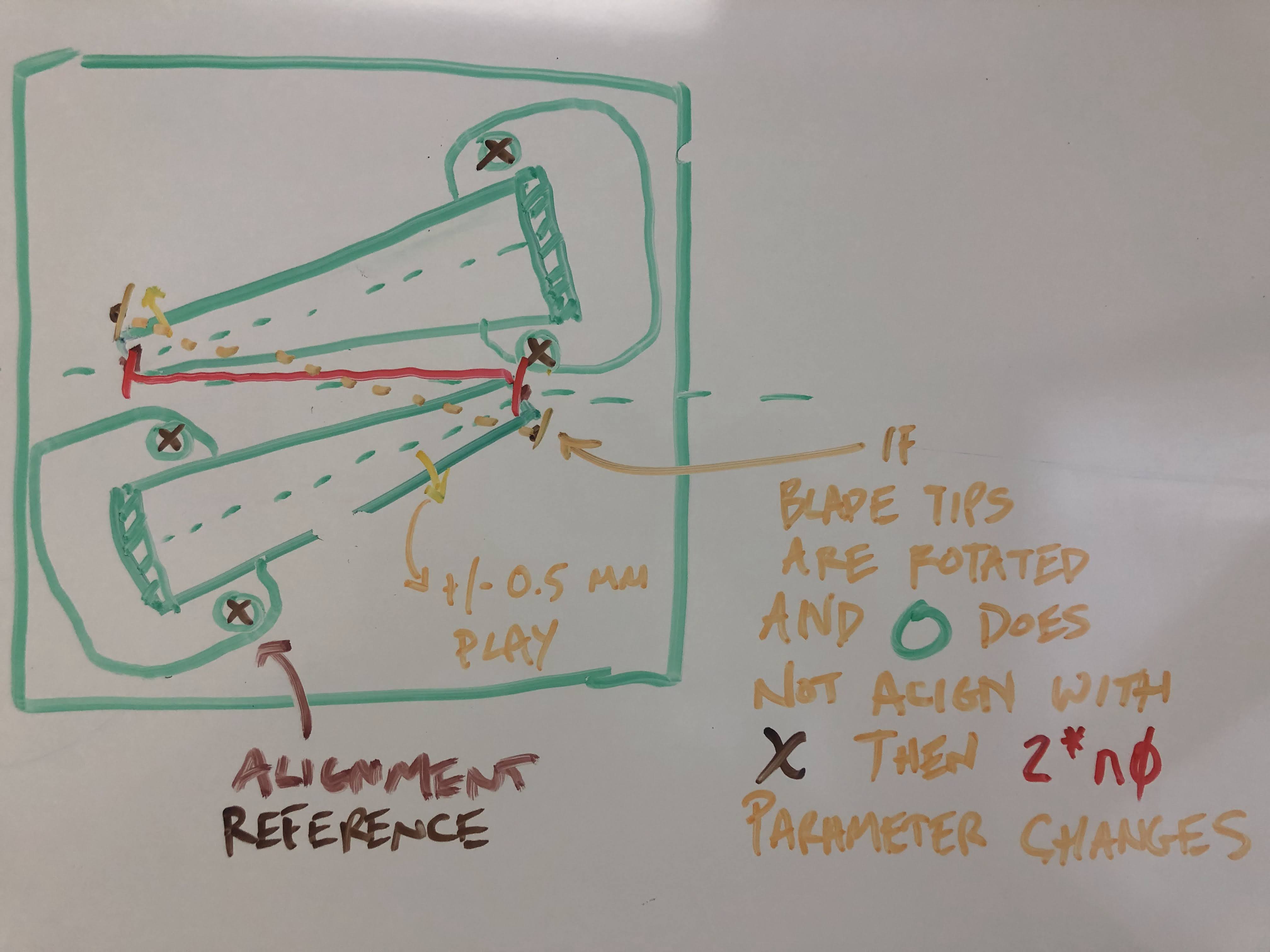
(1) IMG_5624.jpg aides in conveying that the top-down view, lateral alignment of the blade tips are adjustable, and the alignment reference is only visual. Rahul recalls that during the installation and alignment of ZM6, Betsy did adjust this lateral blade alignment in order to achieve the desired yaw alignment of the SUS. For all subsequent HXDS, ZMs 1-5, instead, the blades were left alone, and the whole cage was rotated. We imagine that if the blade tips are pushed differentially outward during adjustment, than this might effect the transverse separation of the blade tip suspension point, thus the parameter (2*) n0, which we imagine will have an impact on the yaw modes. We could also imagine how if they're laterally adjusted in common, that might misalign the principle axis of rotation with the center of mass of the top (M1) mass, which would increase cross coupling. Rahul expects that the slop in the lateral adjustment of each tip is ~+/-0.5 mm. Rahul's going to try to grab an inventory of blade-tip to blade-tip distance for ZMs 1-5 in HAM7 to see if there's a visible pattern there that matches the feature patterns in the TFs.
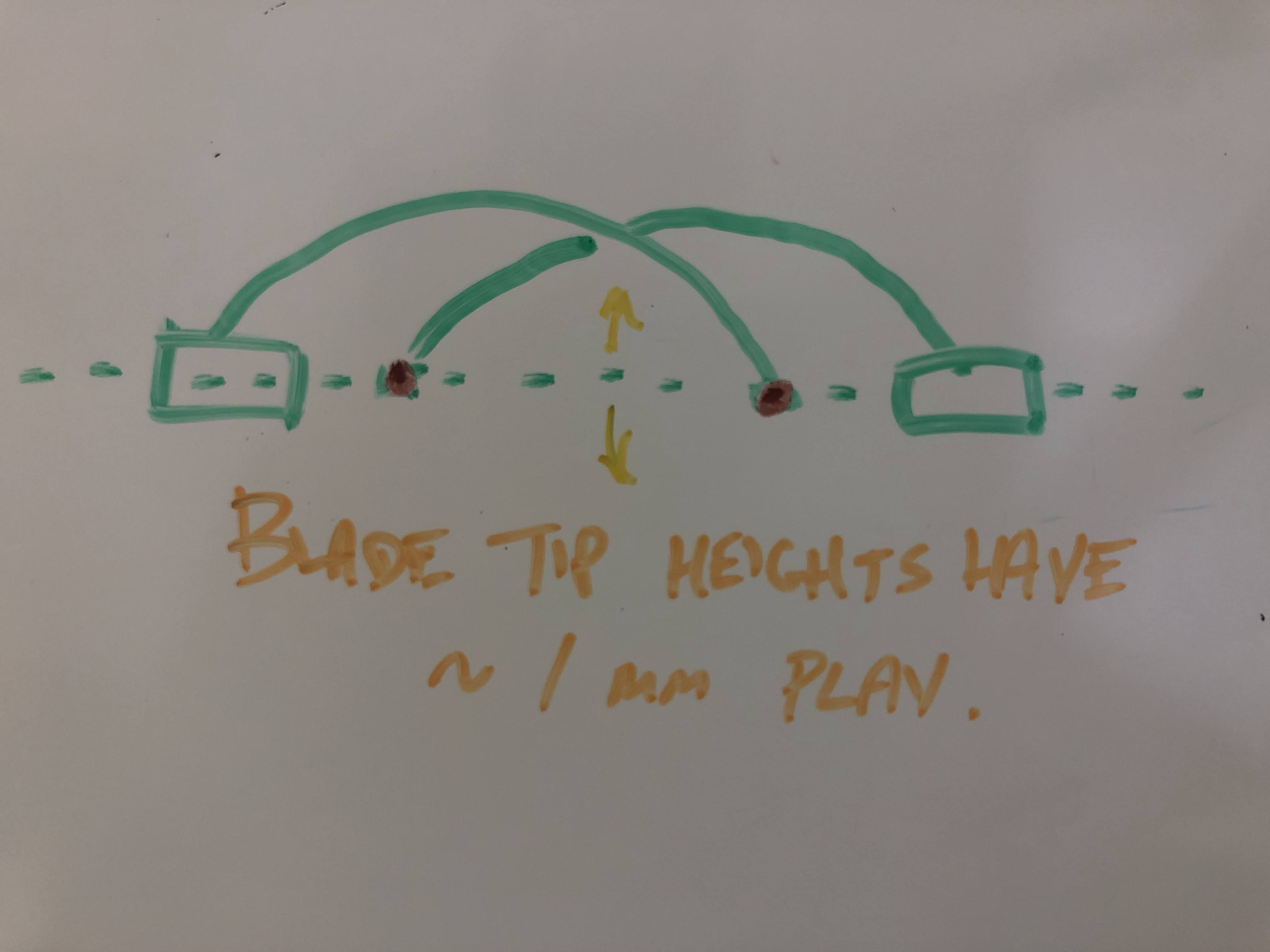
(2) IMG_5625.jpg From a "face on" view, if there were differential vertical position and alignment of the (cage to top-mass) suspension point blade tips with respect to each other, then longitudinal / pitch drive from the back of the top (M1) mass would create some roll and/or yaw. In terms of model parameters, these blade tip heights would correspond to an assymetric "dtop" (which I don't think the model can accommodate at the moment). We don't have observability of the roll transfer function with this top mass OSEM arrangement, but they might perhaps be a source of excess L to P, L to Y, P to Y cross coupling. Rahul expects that the blade tip heights have adjustment of ~+/- 1 mm. Note, we don't expect that the dynamics would be impacted if both tips are collectively in sync vertically, and collectively high or low. That would just result in a DC shift in the vertical position of the whole suspend chain w.r.t. the cage.
Counter point -- but it *might* have an impact in misaligning the coils with the magnets, given that the BOSEM coils are mounted to the cage in essentially a fixed position.
Counter-counter point -- the flags position within the BOSEM coil / sensor should be more limiting that +/- 1 mm.
Counter-counter-counter point -- do the BOSEMs on the HXDS have cam-nut, individual positioning adjustment, and if so, how much is the range of motion?
Rahul will also take visual (and as quantitative as he can) inventory of the symmetry of blade tip heights for ZM1-5.
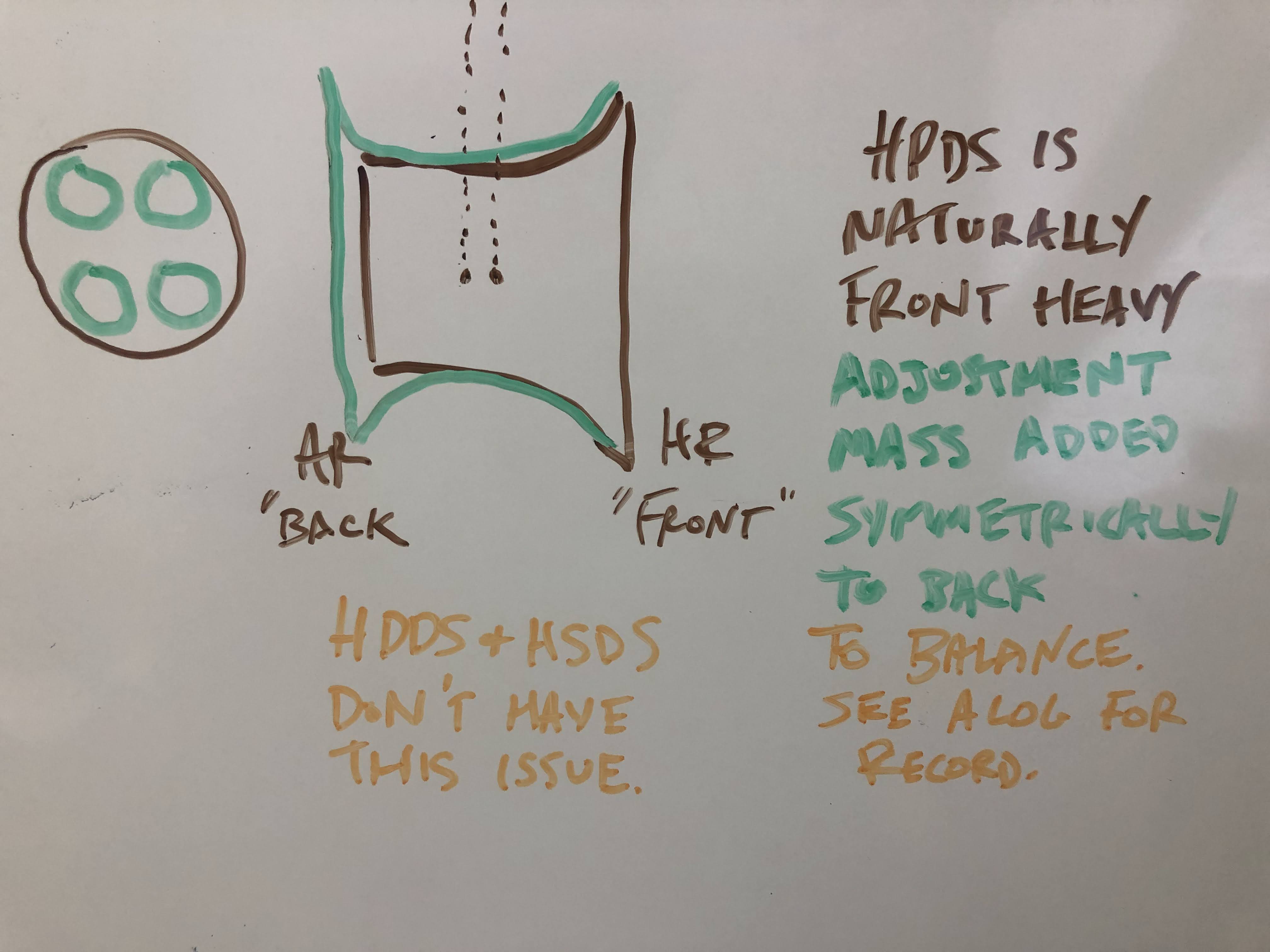
(3) IMG_5626.jpg Rahul's experience with the HPDS (ZM2, ZM4, ZM5) has revealed that the M2 payload mass that contains the PZT actuation system on the optic, is pretty "front" (mirror, HR side) heavy, where as the others, ZM1, ZM3, and ZM6 were relatively easy to balance at a neutral pitch. As such, one could imagine that, with the amount of adjustment mass that alignment-to-neutral required (which is affixed symmetrically to the back in groups of 4), the pitch moment of inertia might be altered. The relationship *between* the M1 and M2 moment of inertia of a non-extra-balance-mass HXDS vs. an extra-balance-mass HPDS might mean than pitch zeros are in different places. Rahul assures me that he's kept good track of what adjustment mass he's used, so we're going gather an inventory of that mass to bound how much we might expect to be able to noodle that M2 pitch moment of inertia dynamical model parameter.
(No visual aides, but also perhaps useful information)
(4) HPDS M1 to M2 Cabling has a clear impact on the amount of 1.6 P and and 2.2. Hz L modes cross coupling into the Y to Y TF. As indicated in the main aLOG above, though, there doesn't seem to be a pattern that ZMs 2, 4, and 5 have worse L to P, or P to Y transfer functions because of this -- because ZM6 (a cable free HSDS) breaks that pattern with equally worse L to P and P to Y TF magnitudes as the HPDS. Rahul says there's no science to finding the right cable routing that reduces the unwanted 1.6 and 2.2 Hz mode features in the Y to Y transfer function, he just iterates re-setting the routing and re-measuring the Y to Y TF until the mode impact is minimized.
(5) The order of construction for these SUS was ZM6, then ZM45, then ZM2, then ZM1 and ZM3, where the groups are several weeks apart is we (well, Rahul and Betsy) spent those installing them as needed. Rahul does feel as though the assembly them got better at constructing the HXDS as they went along, developing tricks that helped clamp wires more consistently, paying closer attention to the alignment of certain elements etc. He shares that because ZM1 shows the closest alignment to the model in terms of P2P and Y2Y inter-mode zeros, where as ZM456 -- even though 6 is an HSDS and 45 are HPDSs -- have a spread of where these features land.
Images attached to this comment