Last week when Sheila and Georgia were performing beam alignment/profile work in HAM7 chamber (see LHO alog 61241), they found that several of the ZMs were swinging a lot and causing the beam to get clipped. To alleviate this issue Jeff. Kissel suggested to adjust the damping gains (a short term fix until the HXDS dynamical model are properly studied and then new damping loop design are implemented). This morning I talked to Sheila and started adjusting the GAIN and also taking osem spectra (before and after) to study the noise. We found that the Longitudinal DoF had large amplitude (as also noted by Georgia) and hence I adjusted these values only (and left the Pitch and Yaw untouched since they were looking good).
Given are the are new GAINs, which works (amplitude reduced by an order or more of magnitude).
| Suspension | GAIN (new) | GAIN (OLD) |
| ZM1 (L DoF) | -0.05 | -1.0 |
| ZM2 (L DoF) | -0.03 | -1.0 |
| ZM3 (L DoF) | -0.02 | -1.0 |
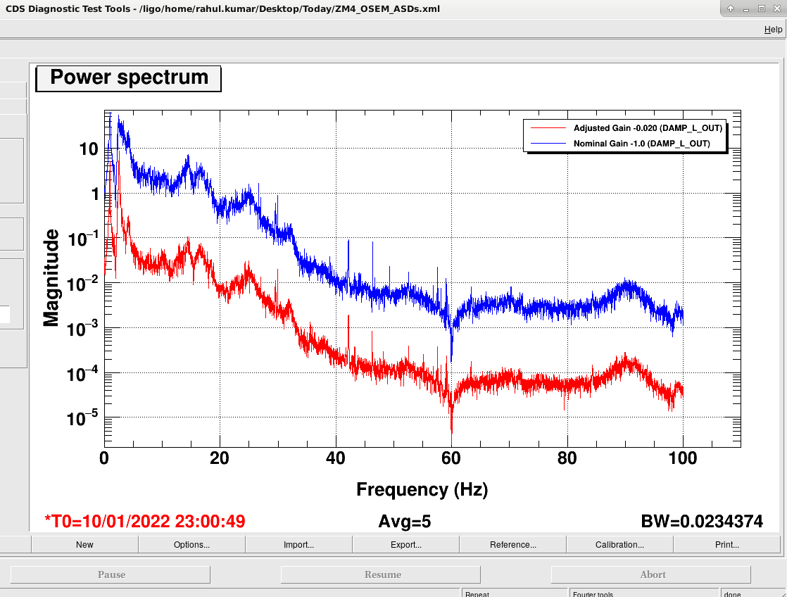
| ZM4 (L DoF) | -0.02 | -1.0 |
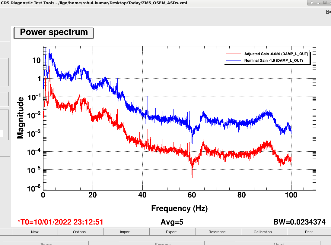
| ZM5 (L DoF) | -0.02 | -1.0 |
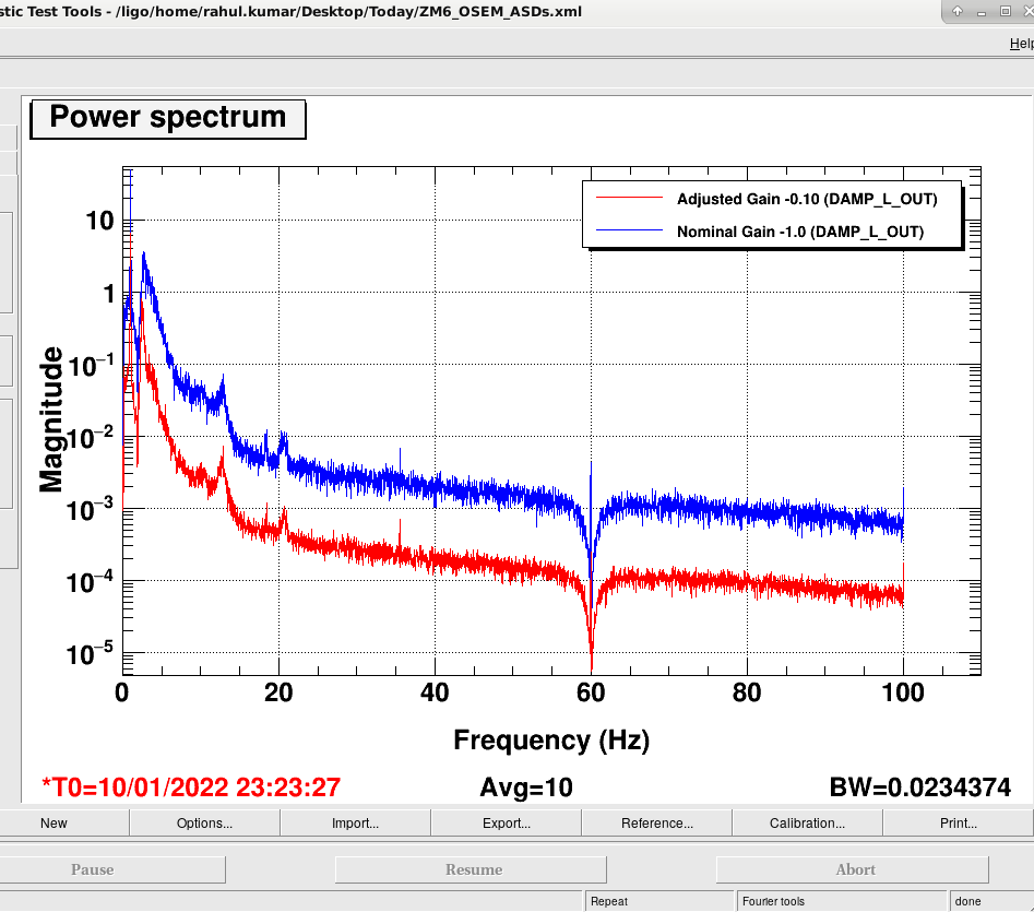
| ZM6 (L DoF) | -0.1 | -1.0 |
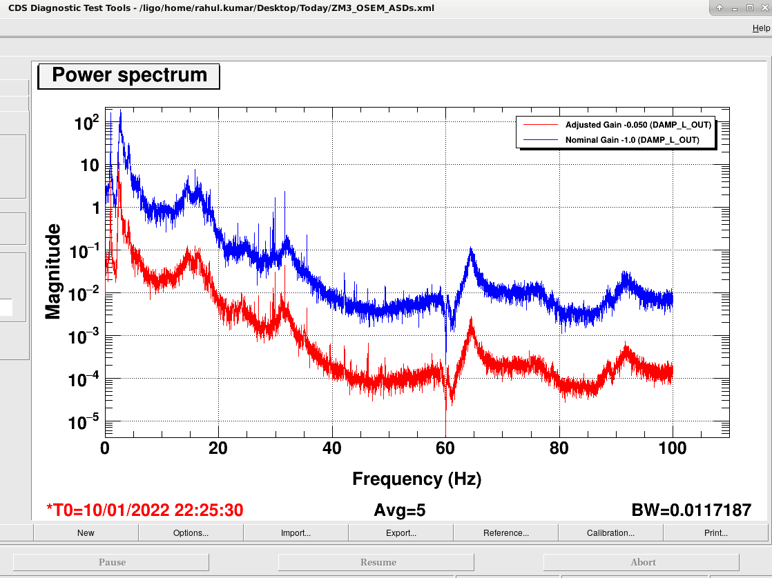
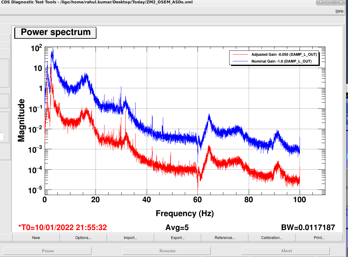
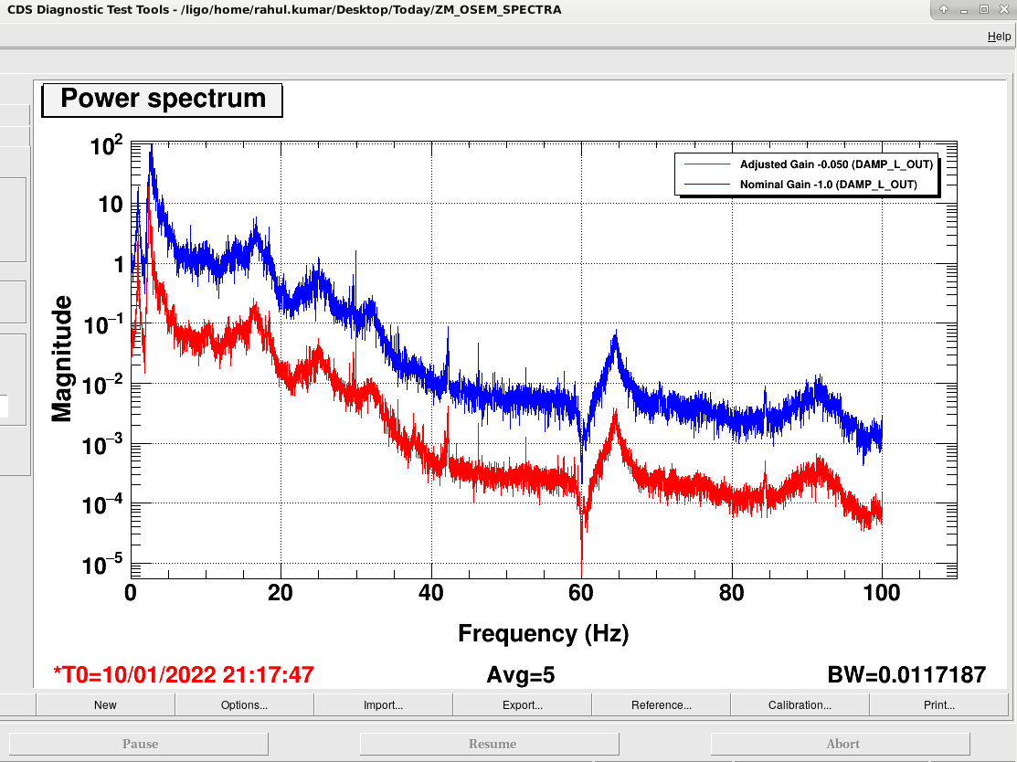
Attached below are the plots (from ZM1 to ZM6) showing the osem spectra (H1:SUS-ZM*_M1_DAMP_L_OUT), comparing before (blue trace) and after (red trace) the gains were adjusted. The L DoF had elevated noise spectra (as against P or Y Dof). I will also add a comparison plot between L,P and Y later on. However the plots attached below shows an improvement in noise (magnitude is reduced is above 10Hz) across the spectrum after the GAINs were adjusted.
I have accepted the new GAINs in the SDF and I hope these settings will help Georgia and Sheila continue their work in HAM7 chamber without any problem.
The above plots were of the control signal of the damping loops, not the error signal.
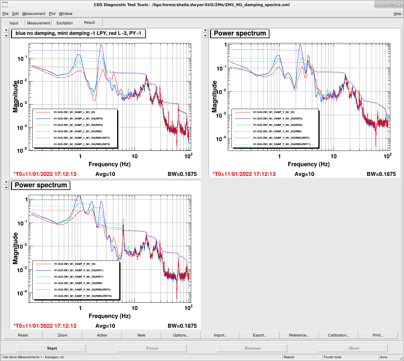
This morning I looked at ZM1 error signals while adjusting the gains, the attached screenshot and template are examples that can be used for the rest of the ZMs, they are plotting error spectra and error signal RMS, on a log frequency scale.
The blue reference shows no damping on, the mint colored spectra show the nominal damping (all gains -1), and the red spectra shows the current configuration, length damping gain set to -3 P and Y left at -1.
Notes on the quick process to find this setting: I noticed that P has the larges RMS with the damping in the nominal state, and that Rahul's reduced gain setting nearly reproduced the undamped spectra. I tried increasing the gain of the P loop, which caused a larger ringing at 0.6Hz. Then based on the observation that the L loop seems to be the one that is reducing the P and Y error signals, I tried stepping up it's gain, which does reduce the RMS for P and Y.
I'm not sure if this will be enough of a reduction to make working in chaber easier, but we can try it. These damping loops will need a more careful look in the future.
Camilla and I can start today with the inspection path set up, which only requires ZM1.

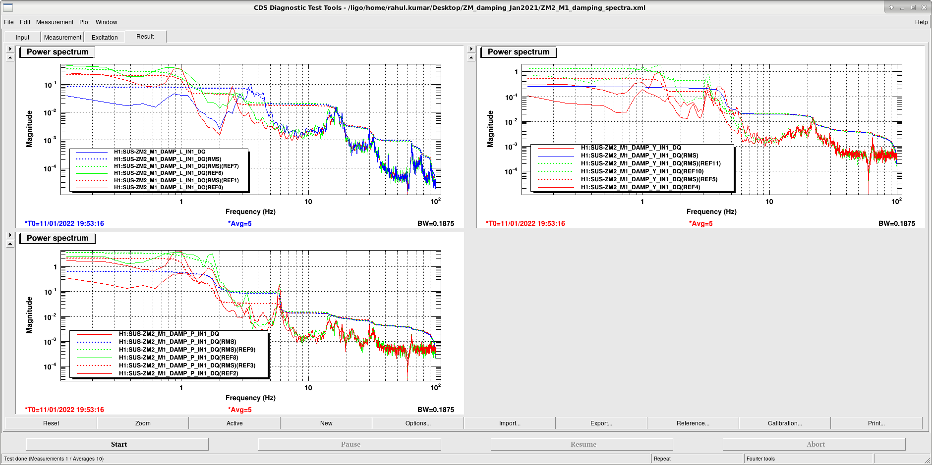
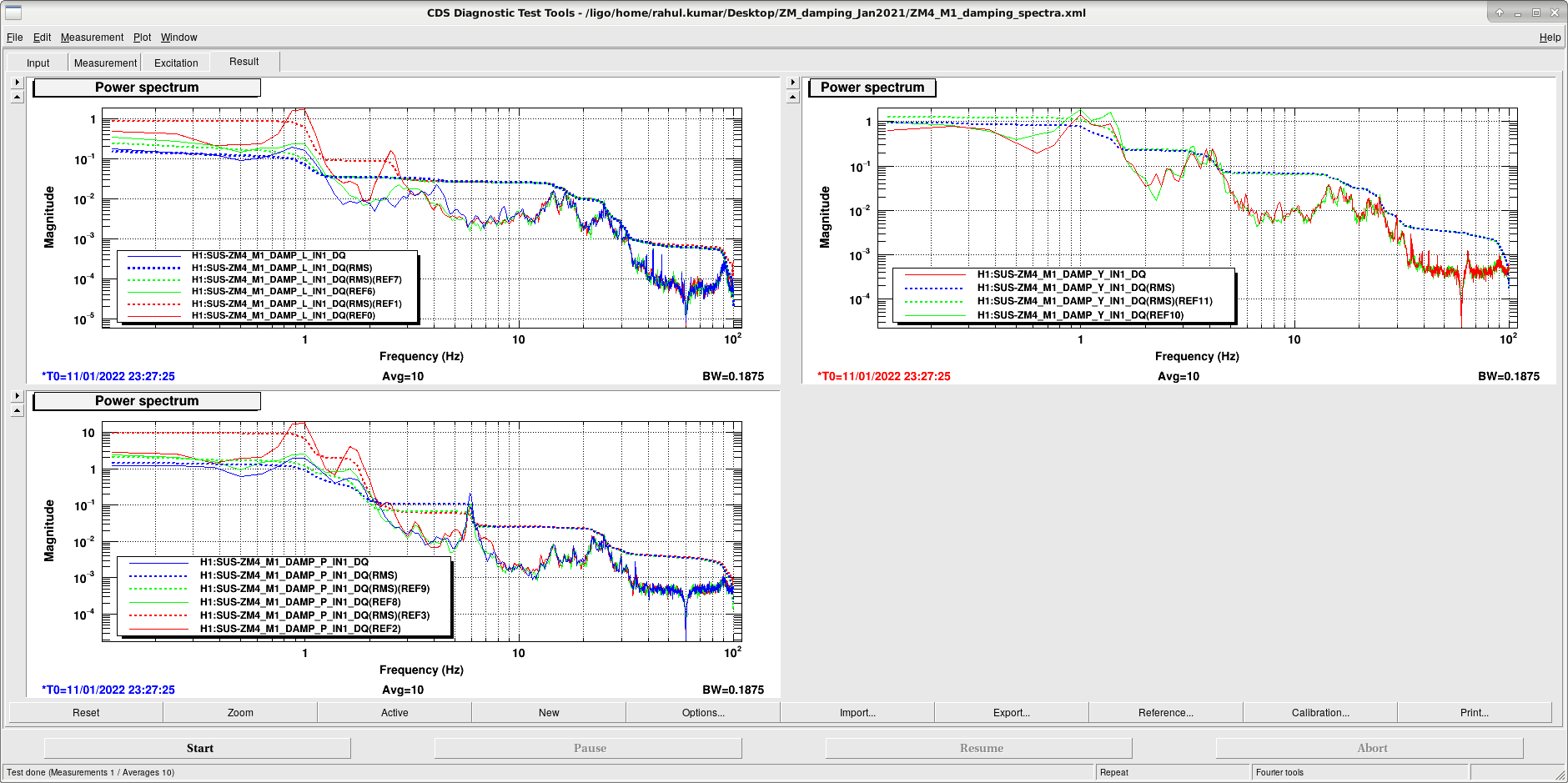
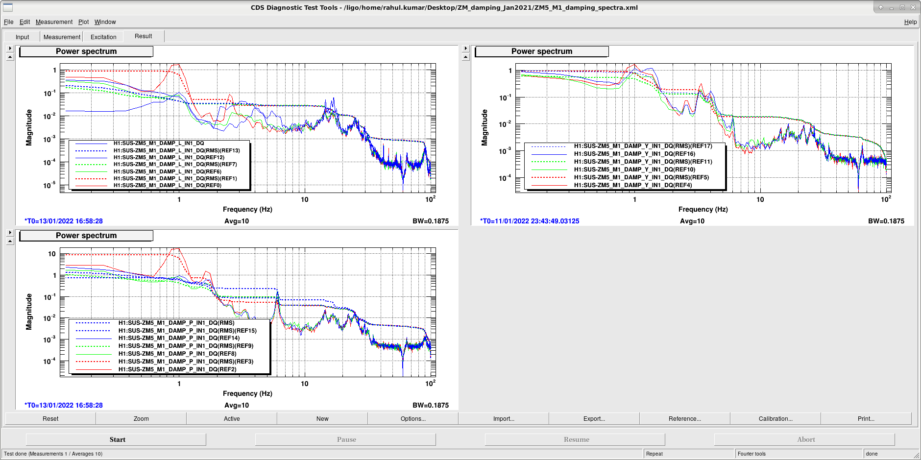
Following up on Sheila's advice, I increased the damping gains and looked at the error spectra and error signal RMS to check if the new settings would damp the suspension better. Attached below are the screnshots of DTT plots (in log scale) for ZM2, ZM3, ZM4, ZM5, ZM6. The solid lines represent error spectra and dashed lines are error signal RMS and the legends in colors represents the following damping gains,
red: damping gain = zero
green: nominal damping gain = -1
blue: adjusted gain= >-1 (played around from -1.1 to -5.0)
The strategy was to adjust (and increase) the damping gain for L DoF and mainly reduce P DoF as much as possible (and bring error spectra rms closer to 0.1 in magnitude) - since Pitch RMS is usually mostly elevated. Also, to check for any unexpected peaks which is not desirable.
Based on the plots attached below, I was able to make some damping improvements in ZM2 (new gain = -3.0), ZM6 (new gain = -1.5), ZM4 (new gain = -2.0), ZM5 (new gain = -1.5). I couldn't find a good setting for ZM3 as the increase in gain was working no better than nominal gain.
The damping gains for Pitch and Yaw were left at nominal values.
I have accepted these new values in the SDF.
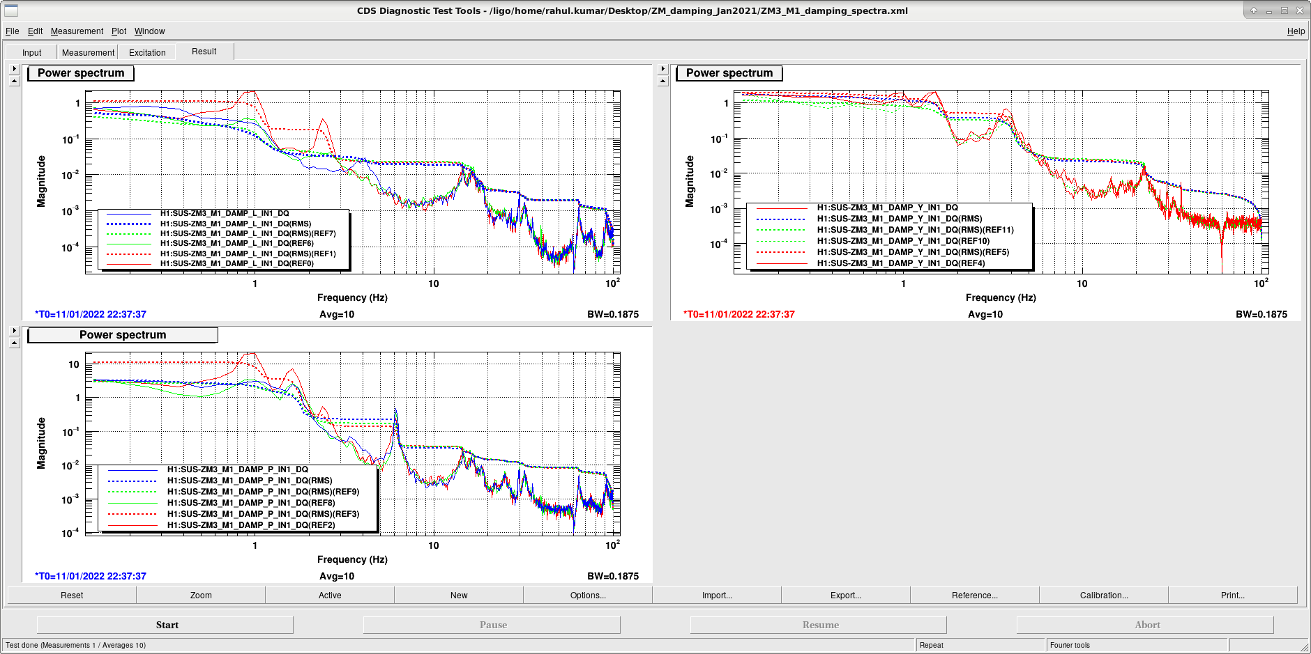

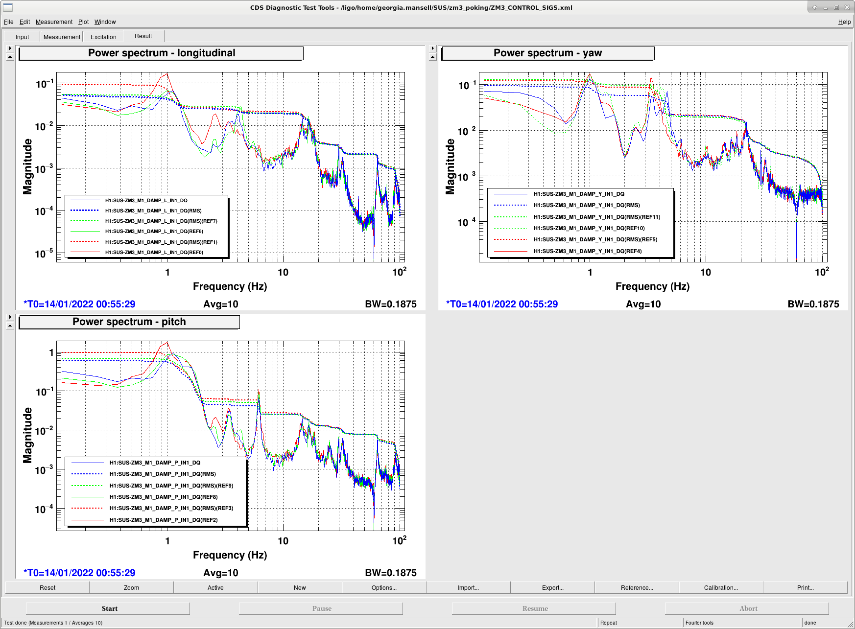
I was curious Rahul's finding that the ZM3 damping loop control signal didn't change much with the gain change. I messed around a bit with the damping loop gains, see attached spectra:
| Trace Colour/DOF | L | P | Y |
| Red | -1 | -1 | -1 |
| Green | -3 | -1 | -1 |
| Blue | -3 | -1 | -5 |
I found when I changed the P gain the 6Hz peak rang up so I left it alone.
I managed less than a factor of 2 reduction in RMS maybe we need to do more involved loopology?